Sign In
Upload
Manuals
Brands
Motorola Manuals
Motherboard
MVME2305
Motorola MVME2305 Manuals
Manuals and User Guides for Motorola MVME2305. We have
1
Motorola MVME2305 manual available for free PDF download: Installation And Use Manual
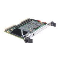
Motorola MVME2305 Installation And Use Manual (167 pages)
VME Processor Module
Brand:
Motorola
| Category:
Motherboard
| Size: 1.02 MB
Table of Contents
Table of Contents
9
Chapter 1 Preparing and Installing the MVME2300-Series Module
17
Introduction
17
Mvme230X Description
17
Mvme230X Module
18
Table 1-1. Mvme230X Models
18
Pmcspan Expansion Mezzanine
19
PCI Mezzanine Cards (Pmcs)
19
Table 1-2. Pmcspan Models
19
Vmesystem Enclosure
20
System Console Terminal
20
Overview of Start-Up Procedures
20
Table 1-3. Start-Up Overview
20
Unpacking the Mvme230X Hardware
23
Preparing the Mvme230X Hardware
23
Mvme230X
25
Figure 1-1. Mvme230X Switches, Leds, Headers, Connectors
25
Setting the Flash Memory Bank A/Bank B Reset Vector Header (J15)
26
Setting the Vmebus System Controller Selection Header (J16)
26
Setting the General-Purpose Software-Readable Header (J17)
27
Pmcs
28
Pmcspan
28
System Console Terminal
28
Figure 1-2. General-Purpose Software-Readable Header
28
Installing the Mvme230X Hardware
29
Taking ESD Precautions
29
Pmcs
29
Primary Pmcspan
31
Figure 1-3. Typical Single-Width PMC Module Placement on Mvme230X
31
Figure 1-4. Pmcspan-002 Installation on an Mvme230X
33
Secondary Pmcspan
34
Figure 1-5. Pmcspan-010 Installation Onto a Pmcspan-002/Mvme230X
35
Mvme230X
37
Installation Considerations
39
Chapter 2 Operating Instructions
41
Introduction
41
Applying Power
41
Mvme230X
42
Switches
42
Abt (S1)
43
Rst (S2)
43
Status Indicators
44
Bfl (Ds1)
44
Cpu (Ds2)
44
Pmc (Ds3)
44
Pmc (Ds4)
44
10/100 BASET Port
44
DEBUG Port
45
PMC Slots
46
PCI MEZZANINE CARD (PMC Slot 1)
46
PCI MEZZANINE CARD (PMC Slot 2)
46
Pmcspan
47
Chapter 3 Functional Description
49
Introduction
49
Features
49
Table 3-1. Mvme230X Features
49
General Description
51
Block Diagram
51
MPC603/604 Processor
51
Figure 3-1. Mvme230X Block Diagram
52
PCI Bus Latency
53
Table 3-2. Power Requirements
53
Table 3-3. Powerpc 60X Bus to PCI Access Timing
54
DRAM Memory
55
Table 3-4. PCI to ECC Memory Access Timing
55
DRAM Latency
56
Figure 3-2. Memory Block Diagram
56
Table 3-5. Powerpc 60X Bus to DRAM Access Timing Using 60Ns Page
57
Table 3-6. Powerpc 60X Bus to DRAM Access Timing Using 50Ns, EDO
58
Flash Memory
59
Flash Latency
60
Ethernet Interface
60
Table 3-7. Powerpc 60X Bus to FLASH Access Timing for Bank B
60
PCI Mezzanine Card (PMC) Interface
61
PMC Slot 1 (Single-Width PMC)
62
PMC Slot 2 (Single-Width PMC)
62
PMC Slots 1 and 2 (Double-Width PMC)
63
PCI Expansion
63
Vmebus Interface
63
Asynchronous Debug Port
64
PCI-ISA Bridge (PIB) Controller
64
Real-Time Clock/Nvram/Timer Function
65
PCI Host Bridge
66
Interrupt Controller (MPIC)
66
Programmable Timers
67
Interval Timers
67
16/32-Bit Timers
67
Chapter 4 Programming the Mvme230X
69
Introduction
69
Memory Maps
69
Processor Bus Memory Map
70
Default Processor Memory Map
70
Table 4-1. Processor Default View of the Memory Map
70
PCI Local Bus Memory Map
71
Vmebus Memory Map
71
Programming Considerations
72
PCI Arbitration
72
Figure 4-1. Vmebus Master Mapping
73
Interrupt Handling
74
Table 4-2. PCI Arbitration Assignments
74
Figure 4-2. Mvme230X Interrupt Architecture
75
DMA Channels
76
Sources of Reset
76
Table 4-3. Classes of Reset and Effectiveness
77
Endian Issues
78
Processor/Memory Domain
78
PCI Domain
78
Vmebus Domain
79
Chapter 5 Ppcbug
81
Ppcbug Overview
81
Ppcbug Basics
81
Memory Requirements
83
Ppcbug Implementation
83
MPU, Hardware, and Firmware Initialization
83
Using Ppcbug
85
Debugger Commands
86
Table 5-1. Debugger Commands
87
Diagnostic Tests
90
Table 5-2. Diagnostic Test Groups
91
Chapter 6 Modifying the Environment
93
Overview
93
CNFG - Conþgure Board Information Block
94
ENV - Set Environment
95
Conþguring the Ppcbug Parameters
95
Conþguring the Vmebus Interface
105
Motorola Computer Group Documents
111
Table A-1. Motorola Computer Group Documents
111
Manufacturersõ Documents
112
Speciþcations
119
Cooling Requirements
121
EMC Regulatory Compliance
122
Introduction
123
Pin Assignments
123
Vmebus Connector - P1
124
Table C-1. P1 Vmebus Connector Pin Assignments
124
Vmebus Connector - P2
126
Table C-2. P2 Connector Pin Assignment
126
Serial Port Connector - DEBUG (J2
128
Ethernet Connector - 10BASET (J3
128
Table C-3. DEBUG (J2)Connector Pin Assignments
128
Table C-4. 10/100 BASET (J3) Connector Pin Assignments
128
CPU Debug Connector - J1
129
Table C-5. Debug Connector Pin Assignments
129
PCI Expansion Connector - J18
134
Table C-6. J18 - PCI Expansion Connector Pin Assignments
134
PCI Mezzanine Card Connectors - J11 through J14
137
Table C-7. J11 - J12 PMC1 Connector Pin Assignments
137
Table C-8. J13 - J14 PMC1 Connector Pin Assignments
138
PCI Mezzanine Card Connectors - J21 through J24
140
Table C-9. J21 and J22 PMC2 Connector Pin Assignments
140
Table C-10. J23 and J24 PMC2 Connector Pin Assignments
141
Solving Startup Problems
143
Table D-1. Troubleshooting Mvme230X Modules
144
Abbreviations, Acronyms, and Terms to Know
149
Advertisement
Advertisement
Related Products
Motorola MVME2301
Motorola MVME2302
Motorola MVME2303
Motorola MVME2304
Motorola MVME2306
Motorola MVME2307
Motorola MVME2308
Motorola MVME2700-42X1
Motorola MVME2700-3431
Motorola MVME2700-3251A
Motorola Categories
Cell Phone
Two-Way Radio
Baby Monitor
Cordless Telephone
Radio
More Motorola Manuals
Login
Sign In
OR
Sign in with Facebook
Sign in with Google
Upload manual
Upload from disk
Upload from URL