Sign In
Upload
Manuals
Brands
GE Manuals
Protection Device
T35 UR Series
GE T35 UR Series Manuals
Manuals and User Guides for GE T35 UR Series. We have
1
GE T35 UR Series manual available for free PDF download: Instruction Manual
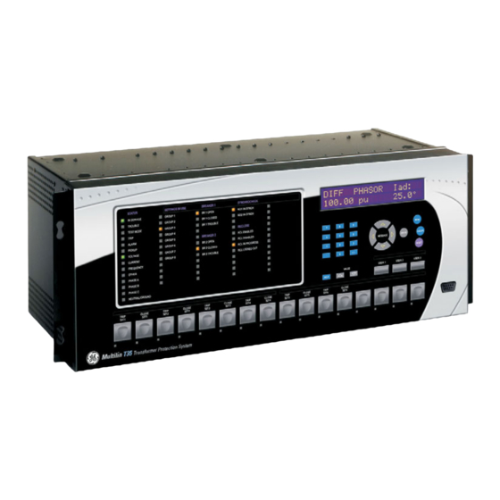
GE T35 UR Series Instruction Manual (568 pages)
Transformer Protection System
Brand:
GE
| Category:
Protection Device
| Size: 9.74 MB
Table of Contents
Table of Contents
3
1 Getting Started
11
Important Procedures
11
Cautions and Warnings
11
Inspection Procedure
12
Ur Overview
13
Introduction to the Ur
13
Hardware Architecture
13
Software Architecture
15
Important Concepts
15
Enervista Ur Setup Software
16
Pc Requirements
16
Installation
16
Configuring the T35 for Software Access
17
Using the Quick Connect Feature
20
Connecting to the T35 Relay
25
Ur Hardware
27
Mounting and Wiring
27
Communications
27
Faceplate Display
27
Using the Relay
28
Faceplate Keypad
28
Menu Navigation
28
Menu Hierarchy
28
Relay Activation
28
Relay Passwords
29
Flexlogic Customization
29
Commissioning
30
2 Product Description
31
Introduction
31
Overview
31
Ordering
32
Replacement Modules
37
Specifications
39
Protection Elements
39
User-Programmable Elements
40
Monitoring
41
Metering
41
Inputs
42
Power Supply
43
Outputs
43
Communication Protocols
44
Inter-Relay Communications
45
Environmental
45
Type Tests
46
Production Tests
46
Approvals
47
Maintenance
47
Description
47
Panel Cutout
49
Rear Terminal Layout
55
Wiring
56
Typical Wiring
56
Dielectric Strength
57
Control Power
57
Ct/Vt Modules
58
Process Bus Modules
60
Contact Inputs and Outputs
60
Transducer Inputs and Outputs
69
Rs232 Faceplate Port
71
Cpu Communication Ports
71
Irig-B
74
Direct Input/Output Communications
75
Description
75
Fiber: Led and Eled Transmitters
77
Fiber-Laser Transmitters
77
Interface
79
Rs422 Interface
82
Rs422 and Fiber Interface
84
And Fiber Interface
84
Ieee C37.94 Interface
85
C37.94Sm Interface
89
4 Human Interfaces
93
Enervista Ur Setup Software Interface
93
Introduction
93
Creating a Site List
93
Enervista Ur Setup Overview
93
Enervista Ur Setup Main Window
96
Extended Enervista Ur Setup Features
97
Settings Templates
97
Securing and Locking Flexlogic Equations
101
Settings File Traceability
103
Faceplate Interface
106
Faceplate
106
Led Indicators
107
Custom Labeling of Leds
110
Display
115
Keypad
115
Breaker Control
115
Menus
116
Changing Settings
119
5 Settings
120
Overview
123
Settings Menu
123
Introduction to Elements
126
Introduction to Ac Sources
127
Product Setup
130
Security
130
Cybersentry Security
134
Display Properties
141
Clear Relay Records
143
Communications
144
Modbus User Map
170
Real Time Clock
171
User-Programmable Fault Report
175
Oscillography
176
Data Logger
179
User-Programmable Leds
180
User-Programmable Self Tests
183
Control Pushbuttons
185
User-Programmable Pushbuttons
186
Flex State Parameters
192
User-Definable Displays
192
Direct Inputs/Outputs
195
Teleprotection
202
Installation
203
Remote Resources Configuration
204
System Setup
205
Ac Inputs
205
Power System
207
Signal Sources
208
Transformer
210
Breakers
222
Disconnect Switches
226
Flexcurves
229
Flexlogic
236
Introduction to Flexlogic
236
Flexlogic Rules
243
Flexlogic Evaluation
244
Flexlogic Equation Editor
244
Flexlogic Timers
244
Flexelements
245
Non-Volatile Latches
250
Grouped Elements
251
Overview
251
Setting Group
251
Transformer Elements
251
Phase Current
251
Ground Current
251
Control Elements
266
Overview
266
Trip Bus
266
Setting Groups
268
Selector Switch
270
Digital Counters
276
Monitoring Elements
278
Inputs and Outputs
286
Contact Inputs
286
Virtual Inputs
288
Contact Outputs
289
Virtual Outputs
291
Remote Devices
292
Remote Inputs
293
Remote Double-Point Status Inputs
294
Remote Outputs
294
Resetting
295
Direct Inputs and Outputs
296
Teleprotection Inputs and Outputs
299
Iec 61850 Goose Analogs
301
Iec 61850 Goose Integers
302
Transducer Inputs and Outputs
304
Dcma Inputs
304
Rtd Inputs
305
Dcma Outputs
307
Testing
311
Test Mode
311
Force Contact Inputs
312
Force Contact Outputs
313
6 Actual Values
315
Overview
315
Actual Values Menu
315
Status
315
Contact Inputs
317
Virtual Inputs
317
Remote Inputs
317
Remote Double-Point Status Inputs
318
Teleprotection Inputs
318
Contact Outputs
318
Virtual Outputs
319
Digital Counters
320
Selector Switches
320
Flex States
320
Ethernet
320
Real Time Clock Synchronizing
321
Direct Devices Status
322
Direct Inputs
322
Iec 61850 Goose Integers
323
Egd Protocol Status
323
Teleprotection Channel Tests
324
Remaining Connection Status
324
Metering Conventions
325
Transformer
328
Sources
329
Tracking Frequency
332
Flexelements
332
Iec 61580 Goose Analog Values
333
Transducer Inputs/Outputs
333
Records
335
User-Programmable Fault Reports
335
Event Records
335
Oscillography
335
Data Logger
336
Breaker Maintenance
336
Product Information
337
Model Information
337
Firmware Revisions
337
7 Commands and
339
Commands
339
Commands Menu
339
Virtual Inputs
339
Clear Records
339
Set Date and Time
339
Relay Maintenance
341
Security
342
Targets Menu
343
Target Messages
343
Relay Self-Tests
343
8 Security
351
User Accounts
351
Overview
351
Enabling the Security Management System
351
Adding a New User
351
Modifying User Privileges
352
Password Requirements
353
Cybersentry
354
Overview
354
Security Menu
356
Description
357
Differential Characteristic Test Examples
369
Introduction
369
Test Example 1
370
Test Example 2
375
Test Example 3
376
Test Example 4
377
Inrush Inhibit Test Procedure
378
Overexcitation Inhibit Test Procedure
379
Commissioning Test Tables
380
Differential Restraint Tests
380
Inrush Inhibit Tests
380
Overexcitation Inhibit Tests
381
10 Maintenance
383
Modules
383
Replace a Module
383
Batteries
385
Replace Battery
385
Dispose of Battery
386
Uninstall and Clear Files and Data
389
Repairs
390
Storage
391
Disposal
392
Parameter Lists
393
Flexanalog Items
393
A.1.1 Flexanalog Items
393
Flexinteger Items
405
A.1.2 Flexinteger Items
405
Modbus Communications
407
Modbus Rtu Protocol
407
Introduction
407
Physical Layer
407
Data Link Layer
407
B.1.1 Introduction
407
Modbus Rtu Crc-16 Algorithm
408
Modbus Function Codes
410
Supported Function Codes
410
Read Actual Values or Settings (Function Code 03/04H
410
Execute Operation (Function Code 05H
411
Store Single Setting (Function Code 06H
411
Store Multiple Settings (Function Code 10H
412
Exception Responses
412
File Transfers
413
Obtaining Relay Files Via Modbus
413
Memory Mapping
415
Modbus Memory Map
415
Data Formats
467
B.4.2 Data Formats
467
Iec 61850
501
Overview
501
Introduction
501
Communication Profiles
501
C.1.1 Introduction
501
File Transfer by Iec 61850
502
Server Data Organization
503
Overview
503
Ggio1: Digital Status Values
503
Ggio2: Digital Control Values
503
Ggio3: Digital Status and Analog Values from Received Goose Data
503
Ggio4: Generic Analog Measured Values
503
C.2.1 Overview
503
Mmxu: Analog Measured Values
504
Protection and Other Logical Nodes
504
Server Features and Configuration
506
Buffered/Unbuffered Reporting
506
File Transfer
506
Timestamps and Scanning
506
Logical Device Name
506
Location
506
Logical Node Name Prefixes
507
Connection Timing
507
Non-Iec 61850 Data
507
Communication Software Utilities
507
Generic Substation Event Services: Gsse and Goose
508
Overview
508
Gsse Configuration
508
Fixed Goose
508
Configurable Goose
508
C.4.1 Overview
508
Ethernet Mac Address for Gsse/Goose
511
Gsse ID and Goose ID Settings
511
Iec 61850 Implementation Via Enervista Ur Setup
512
Overview
512
C.5.1 Overview
512
Configuring Iec 61850 Settings
513
About ICD Files
514
Creating an ICD File with Enervista Ur Setup
518
About Scd Files
518
Importing an Scd File with Enervista Ur Setup
521
Acsi Conformance
523
Acsi Basic Conformance Statement
523
Acsi Models Conformance Statement
523
Acsi Services Conformance Statement
524
Logical Nodes
524
Logical Nodes Table
527
Iec 60870-5-104 Protocol
531
Interoperability
531
D.1.1 Interoperability
531
Point List
539
D.1.2 Point List
539
Device Profile Document
541
Dnp V3.00 Device Profile
541
E.1.2 Implementation Table
544
Dnp Point Lists
548
Binary Input Points
548
Binary and Control Relay Output
549
Counters
550
E.2.3 Counters
550
Analog Inputs
551
E.2.4 Analog Inputs
551
Revision History
553
F.1.1 Revision History
553
Changes to the T35 Manual
554
Abbreviations
557
Standard Abbreviations
557
F.2.1 Standard Abbreviations
557
F.3.1 Ge Multilin Warranty
559
Warranty
560
Advertisement
Advertisement
Related Products
GE T35
GE TBX19
GE TFX22V
GE TFH22PRXAAA
GE TFX25PRYABB
GE TFXB27F
GE TBX14AM
GE TLE Scalable 120
GE TMO2D
GE TLE Scalable Series
GE Categories
Refrigerator
Ranges
Microwave Oven
Air Conditioner
Dishwasher
More GE Manuals
Login
Sign In
OR
Sign in with Facebook
Sign in with Google
Upload manual
Upload from disk
Upload from URL