Sign In
Upload
Manuals
Brands
Emerson Manuals
Microcontrollers
Vission 20/20
Emerson Vission 20/20 Manuals
Manuals and User Guides for Emerson Vission 20/20. We have
1
Emerson Vission 20/20 manual available for free PDF download: Operation And Service Manual
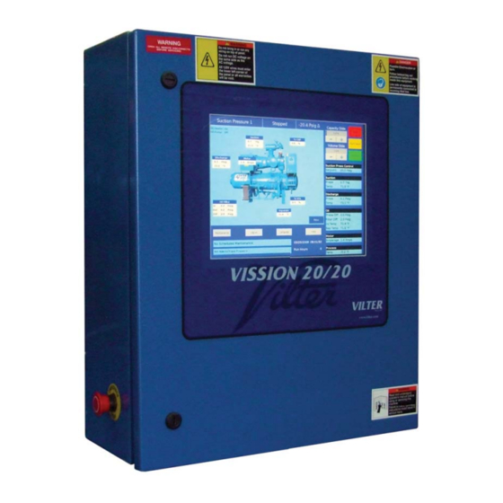
Emerson Vission 20/20 Operation And Service Manual (258 pages)
Vilter
Brand:
Emerson
| Category:
Microcontrollers
| Size: 13.56 MB
Table of Contents
Standard Vilter Warranty Statement
3
Important Message
5
Table of Contents
7
How to Use this Manual
14
Section 1 • Operational Flow Charts
15
Requirements to Start Compressor
15
Critical Compressor Run Logic at Compressor Start
15
Compressor Amperage Load Limiting
15
High Discharge Pressure Load Limiting
15
Suction Pressure Override Load Limit During Temperature Control
16
Section 2 • Installation Recommendations
17
Proper Wiring Sizing
17
Voltage Source
17
Figure 2-1. Vission 20/20 with Individual Transformer
17
Grounding
18
Mixing Voltages
18
DC Signals
18
Figure 2-3. Ground Wiring
18
Wiring Methods
19
Figure 2-5. Correct Transformer Wiring Method
19
Best Practices
20
Section 3 • Hardware Architecture
21
Overview
21
Digital Input/Output (I/O)
22
Table 3-1. Digital I/O
23
Analog Inputs
24
Table 3-2. Analog Inputs
25
Analog Outputs
26
Digital & Analog I/O Boards Layout
27
Digital Outpout Boards
28
Figure 3-3. Digital Output Board Layout
28
Digital Input Boards
29
Digital In-Out Boards
30
Analog Input Boards
31
Analog Input Jumper Tables
32
Analog Output Boards
34
Section 4 • Main Screen Overview
35
Top Status Bar
36
Parameter Bar
37
Figure 4-4. Unit Start Pop-Up Window
38
Bottom Status Bar
39
Splash Screen
40
Section 5 • Menu Screen Overview
41
Navigation Buttons
41
Figure 5-2. Menu Screen with Remote Oil Cooler Enabled
42
Section 6 • Compressor Control
43
Overview
43
Suction Pressure Control and Process Temperature Control
43
Auto-Cycle
44
Figure 6-3. Proportional Band & Setpoint
45
Variable Frequency Drive (VFD)
46
Figure 6-5. VFD One-Step Control Method
47
Rapid Cycling VFD Control
48
Pumpdown Control
49
Pulldown Control
49
Figure 6-8. Compressor Control Screen - Pumpdown/Pulldown Control
50
Control Mode
52
Stop Load & Force Unload
52
Capacity Slide Triggered Outputs
53
Volume Slide Position Offset
54
Soft Load
54
Load Anticipating
54
Oil Control
54
Liquid Injection
54
Figure 6-11. Compressor Control Screen - Oil Control & Liquid Injection Control
55
Section 7 • Alarms and Trips Overview
57
Alarms and Trips Setpoints
57
Figure 7-2. Alarms and Trips Screen - Page 1 as Level 2 User
58
Figure 7-2. Alarms and Trips Screen - Page 2
59
Figure 7-2. Alarms and Trips Screen - Page 3
60
Compressor Inhibits
61
Safety Failure Messages
61
Compressor Warnings
62
Section 8 • Timers Overview
63
Timer Setpoints
63
Figure 8-2. Timers Screen - Page 2
65
Section 9 • Compressor Scheduling
67
Overview
67
Scheduling Setpoint
67
Section 10 • Compressor Sequencing
69
Overview
69
Pressure / Temperature Control Setpoints
69
Capacity Load/Unload Timers
70
Compressor Sequencing Table
71
Table 10-1. Status Symbols
72
Configuration Overview
73
Compressor Setup for Slave Compressor Sequencing
73
Figure 10-5. Placing Slave Compressors in Remote Mode
74
Compressor Setup for Master Compressor Sequencing
75
Section 11 • Condenser Control
77
Overview
77
Condenser Control Setpoint
77
Step Control
78
VFD Settings
79
Figure 11-2. Condenser Control Screen - Page 2
80
Section 12 • Service Options
81
Overview
81
Digital Outputs
81
Figure 12-2. Service Options Screen - Digital Outputs (Page 2)
82
Figure 12-3. Service Options Screen - Digital Outputs (Page 3)
83
Figure 12-4. Service Options Screen - Digital Outputs for Remote Oil Cooler (Page 3)
84
Analog Outputs
85
Section 13 • Instruments Calibration
87
Overview
87
Pressure and Temperature Inputs
87
Motor Current
88
Figure 13-3. Instruments Calibration Screen - Analog Inputs (Page 3)
89
Remote Capacity
90
Analog Inputs
90
Analog Outputs
91
Figure 13-6. Instruments Calibration Screen - Analog Outputs (Page 6)
92
Section 14 • Slide Calibration
93
Overview
93
Capacity Slide Valve Potentiometer
93
Volume Slide Valve Potentiometer
94
Slide Valve Operation
94
Calibrate Slide Valve Actuators
95
Figure 14-3. Menu Screen and Slide Calibration Button (Vission 20/20)
96
Figure 14-4. Photo-Chopper
97
Command Shaft Rotation
98
Slide Valve Troubleshooting Guide
99
Slide Valve Actuator Troubleshooting Guide Blink Code
101
Section 15 • Trend Chart
103
Overview
103
Chart Operation
103
Trend Data Storage
104
Setup
105
Section 16 • Event List
107
Overview
107
Event List Columns
107
Section 17 • Input / Output
109
Overview
109
Figure 17-2. Input/Output Screen - Page 2
110
Figure 17-4. Input/Output Screen - Page 4
111
Figure 17-6. Input/Output Screen - Freeze Data Page
112
Section 18 • Auxiliary Input / Output
113
Overview
113
Digital Inputs
113
Digital Outputs
114
Analog Inputs
114
Figure 18-2. Auxiliary I/O Screen - Digital Outputs (Page 2)
115
Analog Outputs
116
Control
116
Figure 18-4. Auxiliary I/O Screen - Analog Inputs (Page 4)
117
Figure 18-6. Auxiliary I/O Screen - Analog Outputs (Page 6)
118
Section 19 • Configuration
119
Overview
119
Units
119
Time & Date
120
Communications
120
Touchscreen
120
Anti-Recycle
121
Restart on Power Failure
121
Compressor Sequencing
121
Language
121
Model & Refrigerant
121
Compressor Control
122
Optional Function Selection
122
Vilter Only Settings
123
Condenser Control
123
Oil Pump
123
Oil Cooling
123
Motor Current Device
124
Digital Inputs
125
Analog Inputs
126
Analog Outputs
127
Digital Outputs
127
I/O Configuration
128
Section 20 • Data Backup
129
Overview
129
Save / Load
129
Migrate
131
Factory Reset
131
Setpoints Report
132
Section 21 • Maintenance
133
Overview
133
Checklist
133
Notes
134
Log
134
Chart
134
Figure 21-3. Maintenance Screen - Chart
135
Section 22 • User Access
137
Overview
137
Apply
137
Login
138
Manage Accounts
138
Figure 22-3. User Access Screen - VNC Accounts
139
VNC Account
140
Screen Security Levels
140
Section 23 • Help Screen
141
Overview
141
Screen Features
141
Figure 23-2. Help Screen - USB
142
Section 24 • Twin Screw Control
143
Overview
143
Setup - Configuration Screen
143
Operation
144
Slide Calibration - Capacity Slide Valve Potentiometer
144
Figure 24-3. Slide Calibration - Twin Screw Bump Pop-Up Window
145
Section 25 • Cool Compression Control
147
Overview
147
Setup
147
Control Functions
148
Operational Differences from Single Screw
150
Section 26 • Remote Oil Cooler
151
Overview
151
Remote Oil Cooler Setpoint
151
Step Control
152
VFD Settings
152
Figure 26-2. Remote Oil Cooler VFD Screen (Page 2)
153
Appendix A • Vission 20/20 Troubleshooting Guide
155
Vission 20/20 Troubleshooting Guide
155
Appendix B • Vission 20/20 Application Procedures
159
Vission 20/20 Application Procedures
159
Vission 20/20 Compressor Control Setpoints Setup
163
Vission 20/20 Compressor Sequencing Setup
167
Database Backup Procedure
175
Flashcard Replacement Procedure
177
Danfoss Liquid Injection Valve Setup
179
User Access Menu
181
Phoenix Contact PSM-ME-RS485/RS485-P Isolator
205
Advertisement
Advertisement
Related Products
Emerson Varec 2020B Series
Emerson Rosemount 2051
Emerson Rosemount 2090P
Emerson TESCOM 20-1000 Series
Emerson Fisher Control-Disk NPS 20 CL300
Emerson Rosemount 2051T
Emerson Klauke ES 20RMCCFM
Emerson Liebert PEX 2060FA/W/G
Emerson Liebert PEX 2070FA/W/G
Emerson Fisher easy-Drive 200L
Emerson Categories
Controller
Control Unit
Transmitter
Measuring Instruments
Fan
More Emerson Manuals
Login
Sign In
OR
Sign in with Facebook
Sign in with Google
Upload manual
Upload from disk
Upload from URL