Sign In
Upload
Manuals
Brands
Emerson Manuals
Computer Hardware
Liebert CRV
Emerson Liebert CRV Manuals
Manuals and User Guides for Emerson Liebert CRV. We have
3
Emerson Liebert CRV manuals available for free PDF download: User Manual
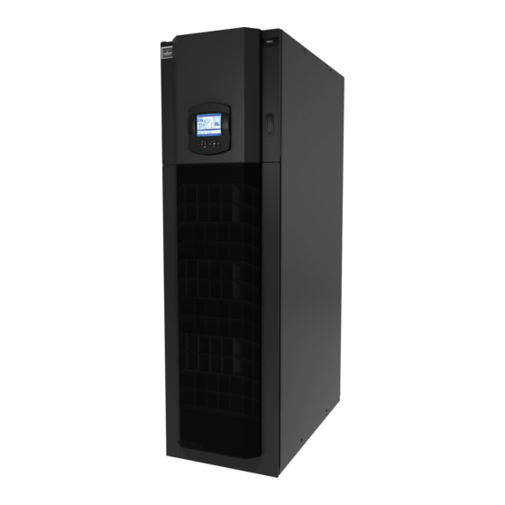
Emerson Liebert CRV User Manual (192 pages)
60Hz 600mm Wide Air-Cooled, Water/Glycol-Cooled and Chilled Water Units 300mm Wide Air-Cooled Units
Brand:
Emerson
| Category:
Air Conditioner
| Size: 8.92 MB
Table of Contents
Table of Contents
3
Save These Instructions
11
1 Liebert Crv Component Location
15
Liebert Crv Component Location Introduction
15
Figure 1 Component Location, Common Components-600Mm (24") Models
15
Figure 2 Component Location-Liebert 300Mm (12") CR019 DX Units
16
Figure 3 Overall Dimensions, Service Area-600Mm (24") Models
17
Table 1 Dry Weight, All Model Types, ± 5
17
Figure 4 Overall Dimensions, Service Area-300Mm (12") DX Models
18
Table 2 Overall Dimensions, Service Area-300Mm (12") Models
18
2 Introduction
19
Product Description
19
Figure 5 Liebert CRV, Front and Rear Views
19
Smartaisle ™ Configuration
20
3 Inspection and Unpacking
21
Equipment Inspection
21
Packing Material
21
Handling
22
Figure 6 Liebert CRV Center of Gravity
22
Table 3 Center of Gravity
22
Table 4 Weights Without Packaging
22
Figure 7 Recommended Unit Handling Equipment
23
Handling the Unit While It Is Packaged
23
Table 5 Shipping Weights
23
Moving the Unit Using Rigging-600Mm (24") Models
24
Figure 8 Moving the Unit Using Rigging
24
Unpacking the Liebert CRV-600Mm (24") Models
25
Figure 9 Unpacking the Liebert CRV
25
Removing the Unit from the Skid
26
Reattaching the Baffle Panel-600Mm (24") Units
27
Figure 10 Removing the 600Mm (24") Unit from the Skid
27
Uncrating and Removing the Liebert CRV from the Skid-300Mm (12") DX Units
28
Figure 11 Removing the Liebert CRV 300Mm (12") DX Unit from the Skid
28
4 Preparing the Liebert Crv for Installation
29
Figure 12 Adjust Leveling Feet-600Mm (24In.) and 300Mm (12In.) Units
29
5 Piping
30
Fluid Connections
30
Refrigeration and Hydraulic Circuits
31
Figure 13 General Arrangement, Liebert MC Condenser-Air-Cooled 600Mm (24") Units with and Without Liebert Lee-Temp Condenser
31
Figure 14 General Arrangement, Fin/Tube Condenser-Air-Cooled 600Mm (24") Units with and Without
32
Liebert Lee-Temp Condenser
32
Figure 15 General Arrangement, Liebert MC Condenser with and Without Liebert
33
Lee-Temp-Air-Cooled 300Mm (12") Units
33
Figure 16 General Arrangement-Water-Glycol Units, 600Mm (24") Models
34
Figure 17 General Arrangement-Chilled Water, 600Mm (24") Models
35
Condensate Drain Piping-Field-Installed
36
Figure 18 Condensate Pumps-600Mm (24") and 300Mm (12") DX Units
36
Gravity Drain-Units Without Factory-Installed Condensate Pump-600Mm (24")
37
Models
37
Figure 19 Gravity Drain Piping-600Mm (24") and 300Mm (12") Units
37
Figure 20 Gravity Drain Connection, 300Mm (12") DX Units Without Condensate Pump
38
Gravity Drain-300Mm (12") DX Units Without Factory-Installed Condensate Pump
38
Humidifier Supply Water-Optional Steam Generating Canister-600Mm (24")
38
Models
38
Requirements of Systems Using Water or Glycol-600Mm (24") Models
38
6 Refrigerant Connections for Air -Cooled Units
41
Piping Guidelines-Air-Cooled Units
41
Figure 21 Connections for Vacuum Creation and Refrigerant Charge-600Mm (24") Models
42
Figure 22 Connections for Vacuum Creation and Refrigerant Charge-300Mm (12") DX Models
42
Figure 23 Top Refrigerant Piping Connections-600Mm (24") Models
43
Figure 24 Bottom Refrigerant Piping Connections-600Mm (24") Models
43
Figure 25 Top Refrigerant Piping Connections-300Mm (12") DX Models
43
Refrigerant Piping-Air-Cooled Models
43
General Piping Layout
44
Liebert Fin/Tube Condenser Selection-600Mm (24") Units
44
Liebert MC Condenser Selection-600Mm (24") and 300Mm (12")CRV Units
44
Table 6 Traditional Open Room 95°F (35°C)/23RH Return Air Conditions
44
Table 9 Condenser Positioning-Liebert MC and Fin/Tube Condenser with or Without Liebert
45
Table 17 Key to Unit Connections in Figure 28
51
Table 18 Indoor Unit Charge R-410A Refrigerant and Oil Charge for Air-Cooled Models
52
Table 19 Interconnecting Piping Refrigerant Charge
52
Table 21 Fin/Tube Condensers Air-Cooled Condenser Refrigerant Charge
52
Evacuation Air-Cooled Models-600Mm (24") and 300Mm (12")Models
53
Table 22 Refrigerant and Oil Charge for Water-Cooled Models-600Mm (24")
53
Table 8 Traditional Open Room 95°F (35°C)/23RH Return Air Conditions
44
Figure 26 Piping Line Cooling Unit
45
Table 10 Liebert CRV Position Relative to the Remote Condenser-Liebert MC and Fin/Tube
45
Table 11 Recommended Refrigerant Line Sizes, Cu, OD, for Liebert MC and VFD Control Fin/Tube Condensers with R-410A with and Without Liebert Lee-Temp
46
Heat Rejection Connection Sizes
47
Table 12 Liebert MC Condenser Piping Sizes for 600Mm (24In.) and 300Mm (12In.) Units
47
Table 14 Piping and Refrigerant Sizes for Liebert Lee-Temp
47
Piping Guidelines for Liebert MC and Fin/Tube Condensers
48
Figure 27 Connection Locations-Air-Cooled 600Mm (24") Models
49
Table 16 Unit Connection Sizes, Air-Cooled Models-600Mm (24") Models
50
Figure 28 Connections-Air-Cooled 300Mm (12") Models
51
Vacuum and Refrigerant Charge
52
Calculating Charging Values for Liebert MC Condenser Systems, Units Without Liebert Lee-Temp ™ Systems
54
Table 23 Target Subcooling for Ambient Outdoor Temperature
55
Table 24 Difference in Subcooling Measurements-Indoor Minus Outdoor
56
Table 25 Liquid Pressure and Temperature Chart
57
Charging Fin/Tube Condenser with Variable Fan Speed Control
59
7 Water Onnections for
60
Glycol Units -600 MM (24") Models
60
Table 26 Water Connection Options
60
Table 27 Volume of CRV Internal Water Circuits
60
W Ater C Onnections for W Ater /G Lycol U Nits —600 MM (24") M Odels
60
Water Connections-Supply Humidifier and Drain Water
61
Glycol Mixture
61
Figure 29 Water Connection Points, Bottom Entry
61
Table 28 Glycol Mixtures
61
Water Connections: Water/Glycol-Cooled Models
62
Notes for Open-Circuit Applications
62
Notes for Closed-Circuit Applications
62
Figure 30 Recommended Drycooler Installation
62
Figure 31 Connections-Water/Glycol Models
63
8 Water Connections for Chilled Water Units -600 MM (24") Units
64
Figure 32 Chilled Water Connections
64
Figure 33 Chilled Water Circuit
65
Figure 34 Connections-Chilled Water Models
66
Table 30 Unit Connections, Chilled Water Models
66
9 Electrical
67
Lectrical Onnections
67
Electrical Field Connections Descriptions
67
Standard Electrical Connections-600Mm (24") Models
67
E Lectrical C Onnections
67
Electrical Connections for Optional Features-600Mm (24") Models
68
Figure 35 Electrical Field Connections-600Mm (24") Models
69
Figure 36 Canbus Communication Connection Liebert CRV and Liebert MC (Premium) Unit
70
Standard Electrical Field Connections-300Mm (12") DX Models
71
Electrical Field Connections for Optional Features-300Mm (12") DX Models
71
Figure 37 Electrical Field Connections-300Mm (12") DX Models
72
Figure 38 Low-Voltage Field Wiring Routing into the Unit-300Mm (12") DX
73
Electrical Connections
74
Figure 39 Serial Tag Location--600Mm (24") Models
75
Figure 40 Remove Electrical Panel and Lower Front Panel-600Mm (24") Models
75
Figure 41 Pull out the Electric Panel-300Mm (12") DX Models
76
Figure 42 Power and Control Cable Entry Points and Routing-600Mm (24") Models
77
Figure 43 Power Cable Routing-Bottom Entry, 300Mm (12") DX Models
78
Figure 44 Liebert Intellislot Cable Routing-Top Entry, 300Mm (12") DX Models
79
Figure 45 Liebert Intellislot Cable Routing-Bottom Entry, 300Mm (12") DX Models
80
Power Supply Cable Connections
81
Protective Features of the Electronically Commutated Fans-All Models
81
Protective Features of Electrical Heaters-600Mm (24") Models
82
Figure 46 Electrical Heating with Temperature Sensor Protection
82
10 Startup
83
Initial Startup
83
Automatic Restart
84
Figure 47 Refrigerant Line Components-600Mm (24") Models
84
Figure 48 Refrigerant Line Components-300Mm (12") DX Models
85
Chilled Water Valve: Chilled Water 600Mm (24") Models
86
Adjust Baffles to Direct Air Properly
86
Figure 49 Position of the Chilled Water Valve Actuator (for 2- or 3-Way Valve)-600Mm (24") Units
86
10.4.1 Adjust Baffles on 600Mm (24") Models
87
Figure 50 Adjust the Baffles to Ensure Correct Airflow Direction-600Mm (24") Models
87
10.4.2 Adjust Baffles on 300Mm (12") Models
88
Figure 51 Adjust the Baffles to Ensure Correct Airflow Direction-300Mm (24") Models
88
10.4.3 Adjust Blocker Plate-600Mm (24") Models
89
Figure 52 Adjust Air-Blocking Plate-600Mm (24") Models
89
11 Liebert Icom ® Control
90
Figure 53 Liebert Icom ® Default Screen Symbols
91
Table 31 Keyboard Icons and Functions
91
Control Interface
92
11.1.1 Navigating through the Liebert Icom Menus
92
Figure 54 User Menu Icons and Descriptions
92
Figure 55 Service Menu Icons
93
Table 32 Service Menu Icons
93
11.1.2 Accessing Submenus
94
Figure 56 System View Screen
94
Figure 57 Unit View Screen
94
11.1.3 Submenus
95
Figure 58 Main Screens, User, Service and Advanced
95
Figure 59 Screen Transition
96
Figure 60 Menu Tree-Stand-Alone Units or Units Not in a Network
97
11.1.4 Viewing Multiple Units with a Networked Large Display
98
Figure 61 Liebert CRV System Screen
98
Figure 62 Menu Tree-Liebert Crv's in a Network
99
Liebert Icom Display Readout
100
Figure 63 Display User Menu - Display Setup
100
Figure 64 Liebert Icom Menu Components for Liebert CRV
101
Figure 65 Liebert Icom ® Menu Components for Liebert CRV
102
Liebert CRV Operation-Liebert Icom Control
103
Figure 66 Service Menu - Setpoint Screen
103
11.3.1 Entering a Password
104
11.3.2 Cooling
105
Figure 67 Service Menu Setpoint Screen for Cooling
105
11.3.3 Fan Speed
106
11.3.4 Air Flow
106
Figure 68 Service Menu Setpoint Screen for Fan Speed
106
Figure 69 Service Menu Setpoint Screen for Airflow
106
11.3.5 Humidification
107
Figure 70 Service Menu Setpoint Screen for Humidification
107
Liebert Icom User Menu Screens
108
Figure 71 User Menus-Setpoints Parameters Screen
108
Figure 72 User Menus-Spare Parts Screen
109
Figure 73 User Menus-Event Log Screen
109
Figure 74 User Menus-Network Screen
110
Figure 75 User Menus-Sensor Data Parameters Screen
110
Figure 76 User Menus-Sensor Data Parameters Screen
111
Figure 77 User Menus-Display Setup Parameters Screen
112
Figure 78 User Menus-Total Run Hours Parameters Screen
113
Figure 79 User Menus-Condenser Timer Screen
113
Figure 80 User Menus-Condenser Timer Screen
114
Liebert Icom Service Menu Screens
115
Figure 81 Service Menus-Setpoints Parameters Screen
115
Figure 82 Service Menus-Setpoints Parameters Screen
116
Figure 83 Service Menus-Setpoints Parameters Screen
117
Figure 84 Service Menus-Setpoints Parameters Screen
118
Service-Standby Settings Menu Screen
119
Figure 85 Service Menus-Standby Settings / Lead-Lag Parameters Screen
119
Service-Wellness Menu Screens
120
11.7.1 Calculating Unit Wellness
120
Figure 86 Service Menus-Wellness Basic Settings Screen
121
Figure 87 Service Menus-Wellness Motor Settings Parameters Screen
122
Figure 88 Service Menus-Wellness Compressor 1 Settings Parameters Screen
122
Figure 89 Service Menus-Wellness Electric Heater 1 Settings Parameters Screen
123
Figure 90 Service Menus-Wellness Humidifier Settings Parameters Screen
123
Service-Diagnostics Menu Screens
124
Figure 91 Service Menus-Diagnostics / Service Mode Parameters Screen
124
Figure 92 Service Menus-Diagnostics / Service Mode Parameters Screen
124
Figure 93 Service Menus-Diagnostics / Service Mode Parameters Screen
125
Figure 94 Service Menus-Diagnostics / Service Mode Parameters - Page 4 CW Models
126
Figure 95 Service Menus-Diagnostics / Service Mode Parameters - Page 4 DX Models
126
Figure 96 Service Menus-Diagnostics / Service Mode Parameters Screen
127
Figure 97 Service Menus-Diagnostics / Service Mode Parameters Screen
127
Service-Set Alarms Menu Screens
128
Figure 98 Service Menus Figure 85 Diagnostics / Service Mode Parameters Screen
128
Figure 99 Service Menus-Set Alarms Parameters Screen
128
Figure 100 Service Menus-Set Alarms Parameters Screen
129
Figure 101 Service Menus-Set Alarms Parameters Screen
129
Service-Sensor Calibration Menu Screens
130
Figure 102 Service Menus-Set Alarms Parameters Screen
130
Figure 103 Service Menus-Set Alarms Parameters Screen
130
Figure 104 Service Menusfigure 89 Sensor Calibration / Setup Parameters
130
Figure 105 Service Menus-Sensor Calibration / Setup Parameters
131
Figure 106 Service Menus-Sensor Calibration / Setup Parameters
131
Service-System/Network Unit-Level Setup Menu Screens
132
Figure 107 Service Menus-Sensor Calibration / Setup Parameters
132
Figure 108 Service Menus-System / Network Setup Parameters-System - Page 1 for the Display
132
Figure 109 Service Menus-System / Network Setup Parameters-Large Display Only System
133
Figure 110 Service Menus-System/Network Setup Parameters Unit- Page 1 for the Board
134
Figure 111 Service Menus-System/Network Setup Parameters Unit - Page 2 for the Board
135
Service-Options Setup Menu Screens
136
Figure 112 Service Menus-Options Setup Parameters
136
Figure 113 Service Menus-Options Setup Parameters
137
Figure 114 Service Menus-Options Setup Parameters
137
Figure 115 Service-Service Contact Menu
138
Table 34 Service Contact Info Parameters
139
Service-Remote Sensors Menu Screens
140
Figure 116 Service Menus-Remote Sensor Setup
140
12 Operation in Teamwork Mode
141
Unit-To-Unit Network Wiring
141
Liebert Icom U2U Ethernet Network
141
Wiring a Liebert Icom U2U Network
142
Figure 117 U2U Network Setup
142
Figure 118 U2U Network Diagram-600Mm (24In. ) Liebert CRV
143
Teamwork Modes
144
Figure 119 U2U Network Diagram-300Mm (12In. ) Liebert CRV
144
12.4.1 Application of Teamwork Modes
145
12.4.2 no Teamwork
145
Figure 120 Teamwork Modes and Sensor Management
145
Teamwork Mode 1
146
Figure 121 Teamwork Mode 1 with Three Cooling Units
147
Teamwork Mode 2
147
12.4.6 Standby-Rotation
148
Teamwork Mode 3 (Optimized Aisle)
148
Table 35 Teamwork Mode 1 or 3, Definition of Serial, Parallel and Local
149
13 Remote Rack Sensor Wiring
150
DIP Switch Settings
150
Figure 122 2T Rack Sensor
150
Figure 123 DIP Switches in 2T Sensors
150
Set 2T Rack Sensor Identities-DIP Switch Settings
151
Figure 124 Setting DIP Switches for 2T Sensors
151
Table 36 DIP Switch Settings
151
Terminating the Last 2T Sensor on a Network
152
13.3.1 Using the Factory-Supplied Plug to Terminate the Last 2T Sensor on a Network
152
13.3.2 Using Jumper to Terminate the Last 2T Rack Sensor on a Network
152
Figure 125 Termination with Factory-Supplied Plug
152
Figure 126 Termination Jumper Setting
153
Figure 127 Removing the Remote Temperature/Humidity Sensor Cover and Setting DIP Switches
154
Canbus and Ethernet Cable Wiring
155
Figure 128 Canbus Wire Cable with Grounding Wire
156
Route the Canbus Wire into the Cooling Unit-600Mm (24")
157
Figure 129 Route the Canbus Wire into the Cooling Unit-600Mm (24")
157
Route the Canbus Wire into the Cooling Unit-300Mm (12")
158
Sensor Location and Mounting
159
Figure 130 Top Entry Route the Canbus Wire into the Cooling Unit-300Mm (12") DX
159
Figure 131 2T Rack Sensors Installed on Neighboring Racks-600Mm (24") Models
160
Figure 132 2T Rack Sensors Installed on Neighboring Racks-300Mm (12") Models
161
Remote Rack Sensor Operation and Rack View Setup
162
Figure 133 Remote Sensor Setup, Page 1 of 1
162
14 Operation
163
Figure 134 Temperature and Humidity Sensor Terminal, Viewed from the Rear of the Unit-600Mm
163
Figure 135 Temperature and Humidity Sensor and Filter Clog Sensor Viewed from Front of Unit-300Mm
163
Alarms/Events
165
15 Calibration and Regulation after Startup
170
Thermostatic Expansion Valve
170
15.1.1 Determine Suction Superheat
170
15.1.2 Adjust Superheat Setting with the TEV
170
Environmental Protection
170
Calibrating Electrical Components
170
Table 37 Table
170
16 Maintenance
171
Safety Instructions
171
Facility Fluid and Piping Maintenance for Water and Glycol Systems
172
Glycol Solution Maintenance
172
Spare Parts
172
Maintenance Schedule
172
Table 39 Maintenance Schedule
173
Inspect and Replace the Air Filters-600Mm (24") Models
174
Figure 136 Air Filter Location and Input Power Safety Switch-600Mm (24") Models
174
Figure 137 Remove the Air Filters-600Mm (24") Models
175
Figure 138 Differential Pressure Switch Tubes-600Mm (24") Models
175
Inspect and Replace the Air Filters-300Mm (12") Models
176
Figure 139 Remove the Air Filters 300Mm (12") Models
176
Figure 140 Differential Pressure Switch Components, 300Mm (12") DX Models
177
Condensate Drain and Condensate Pump Systems
178
16.8.1 Condensate Drain
178
16.8.2 Condensate Pump, Dual-Float
178
Air-Cooled Condenser and Drycoolers
178
16.10 Electrical Heaters
178
Figure 141 Condensate Pump
178
16.11 Replace a Fan
179
Fan Replacement on 600Mm (24") Models
179
Figure 142 Liebert CRV Fan Assembly Components
179
16.12 Considerations When Dismantling the Unit
180
16.13 F-Gas Regulation (EC) No. 842/2006
180
17 Troubleshooting
182
Table 40 Unit Diagnostics
182
Table 41 Liebert Icom ® Medium Control Board Dipswitch Settings
184
Appendix A-Humidifier-600Mm(24") Unitsonly.
185
Principal of Operation
185
Figure 143 General Diagram-Humidifier Operation
185
Figure 144 Water Connection to Humidifier
186
Humidifier Water Connectionhumidifier Water Connection
186
Humidifier Water Supply and Plumbinghumidifier Water Supply and Plumbing
186
Cylinder Replacementcylinder Replacement
187
Humidifier Startup and Operationhumidifier Startup and Operation
187
Low Water Conductivitylow Water Conductivity
187
Figure 145 Sensor Pins, Cylinder Plugs
188
Humidifier Troubleshootinghumidifier Troubleshooting
189
Table 42 Humidifier Troubleshooting
189
Appendixa - Humidifier -600 MM (24") Units Only
185
Appendixb - Remote Rack Sensor Troubleshooting
190
Figure 146 Canbus and Ethernet Cable Wiring
190
Appendix B-Remoteracksensortroubleshooting.
191
Starting Point
191
Advertisement
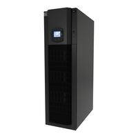
Emerson Liebert CRV User Manual (140 pages)
24-Inch Wide, Air-Cooled, Water/Glycol-Cooled and Chilled Water
Brand:
Emerson
| Category:
Air Conditioner
| Size: 9.08 MB
Table of Contents
Table of Contents
3
1 Liebert Crv Component Location
12
Figure 1 Component Location, Common Components—All Models
12
Figure 2 Component Location - Liebert CR035RA, CR020RA Air-Cooled Units
12
Figure 3 Component Location - Liebert CR035RW, CR020RW Water/Glycol-Cooled Units
13
Figure 4 Component Location - Liebert CR040RC Chilled Water Units
13
Figure 5 Overall Dimensions / Service Area
14
Table 1 Dry Weight, All Model Types, ± 5
14
2 Introduction
15
Product Description
15
Figure 6 Liebert CRV, Front and Rear Views
15
3 Inspection and Unpacking
16
Equipment Inspection
16
Packing Material
16
Handling
16
Figure 7 Liebert CRV Center of Gravity
16
Figure 8 Recommended Unit Handling Equipment
17
Handling the Unit While It Is Packaged
17
Table 2 Center of Gravity
17
Table 3 Weights Without Packaging
17
Table 4 Shipping Weights
17
Moving the Unit Using Rigging
18
Unpacking the Liebert CRV
18
Removing the Unit from the Skid
19
Appendix A-Humidifier.
19
Appendix B-Electricaldata.
19
Appendix C-Electricalfieldconnectionsdescriptions.
19
Appendix D-Refrigeration Andhydrauliccircuits.
19
Figure 10 Unpacking the Liebert CRV
19
Reattach the Baffle Panel
20
Figure 11 Removing the Unit from the Skid
20
4 Prepare the Liebert Crv for Installation
21
Figure 12 Adjust Leveling Feet
21
5 Piping
22
Fluid Connections
22
Condensate Piping-Field-Installed
23
Humidifier Supply Water-Optional Steam Generating Canister
23
Figure 13 Gravity Drain
23
Requirements of Systems Using Water or Glycol
24
6 Refrigerant Connections
26
Piping Guidelines-Air-Cooled Units
27
Refrigerant Piping-Air-Cooled Models
27
Figure 14 Top Refrigerant Piping Connections
27
Figure 15 Bottom Refrigerant Piping Connections
27
General Layout
28
Table 5 Condenser Positioning
28
Table 6 Liebert CRV Position Relative to the Remote Condenser
28
Pipe Diameter and Thickness
29
Figure 16 Pipeline Air Conditioner - Condenser
29
R-410A Cu, OD
29
Table 7 Piping and Refrigerant Sizes for Liebert Lee-Temp ™ Condensers with R-410A
29
R-410A
30
With R-410A, Cu, OD
30
Installing Piping
31
Figure 17 Connections—Air-Cooled Models
32
Table 11 Unit Connections, Air-Cooled Models
33
Vacuum and Refrigerant Charge
34
Table 12 R-410A Refrigerant and Oil Charge for Air-Cooled Models
34
Table 13 Refrigerant Charge
34
Table 14 Air-Cooled Condenser Refrigerant Charge
34
Table 15 Refrigerant and Oil Charge for Water-Cooled Models
34
Evacuation Air-Cooled Models
35
Figure 18 Connections for Vacuum Creation and Refrigerant Charge
35
7 Water
37
Water Connections-Supply Humidifier and Drain Water, All Models
37
Figure 19 Water Connection Points, Bottom Entry
37
Table 16 Water Connection Options
37
Table 17 Volume of CRV Internal Water Circuits
37
Glycol Mixture
38
Water Connections: Water/Glycol-Cooled Models
38
Notes for Open-Circuit Applications
38
Notes for Closed-Circuit Applications
38
Table 18 Glycol Mixtures
38
Chilled Water Connections: Chilled Water Units
39
Figure 20 Chilled Water Connections
39
Figure 21 Chilled Water Circuit
39
Figure 22 Air Bleeding Valve Position CW
40
Figure 23 Connections—Water/Glycol Models
41
Table 19 Unit Connections, Water/Glycol-Cooled Models
42
Figure 24 Connections—Chilled Water Models
43
Figure 25 Recommended Drycooler Installation
44
Table 20 Unit Connections, Chilled Water Models
44
8 Electrical Onnections
45
Electrical Connections
45
Figure 26 Remove Electrical Panel and Lower Front Panel
45
Figure 27 Power and Control Cable Entry Points and Routing
46
Power Supply Cable Connections
46
Protective Features of the Electrically Commutated Fans
47
Protective Features of Electrical Heaters
47
Figure 28 Electrical Heating with Temperature Sensor Protection
47
9 Startup
48
Initial Startup
48
Automatic Restart
49
Figure 29 Refrigerant Line Components
49
Chilled Water Valve: Chilled Water Models
50
Adjust Baffles to Direct Air Properly
50
Figure 30 Position of the Chilled Water Valve Actuator (for 2- or 3-Way Valve)
50
Figure 31 Adjust the Baffles to Ensure Correct Airflow Direction
51
Remote Rack Sensor Wiring
52
Figure 32 Adjust Air-Blocking Plate
52
DIP Switch Settings
53
Figure 33 Figure 2T Rack Sensor
53
Figure 34 DIP Switches in 2T Sensors
53
Table 21 DIP Switch Settings
53
Figure 35 Setting 2T Sensor DIP Switches
54
Set 2T Rack Sensor Identities-DIP Switch Settings
54
Terminating the Last 2T Sensor on a Network
54
Figure 36 Termination Jumper Setting
55
Route the CAN Bus Wire into the Cooling Unit
55
Figure 37 2T Rack Sensors Installed on Neighboring Racks
56
Installing 2T Sensors on Racks
56
Figure 38 Rack Setup Screen, Page 1 of 3
57
Figure 39 Rack Setup Screen, Page 2 of 3
57
Remote Rack Sensor Operation and Rack View Setup
57
Figure 40 Rack Setup Screen, Page 3 of 3
58
Figure 41 Rack Overview Screen
58
10 Liebert Icom ® Control
59
Table 22 Keyboard Icons and Functions
59
Navigating through the Liebert Icom Menus
60
Control Interface
60
Accessing Submenus
60
Entering a Password
61
Figure 43 Entering a Password
61
Figure 44 Menu Tree—Large Display, Stand-Alone
62
Viewing Multiple Units with a Networked Large Display
63
Figure 45 Menu Tree—Large Display, Networked
63
Figure 46 User Menu Icons
64
Table 23 User Menu Icons
64
Figure 47 Service Menu Icons
65
Table 24 Service Menu Icons
65
Liebert Icom ® Display Readout
67
Figure 48 Liebert CRV System Screen
67
Liebert Icom ® Control Setup
69
Figure 50 Setpoint Screen
69
Event Log
70
Spare Part List
70
Wellness-Next Maintenance Calculation
70
Calculation of Next Maintenance and Diagnostics
70
Table 25 Controlling Sensor Settings
70
Liebert CRV Operation-Liebert Icom ® Control
72
Cooling
72
Heating
72
Air Flow
72
Humidification
72
Liebert Icom ® User Menu Screens
73
Figure 51 User Menu Icons
73
Figure 52 Setpoints Parameters Screen
73
Figure 53 Sensor Data Parameters Screen
74
Figure 54 Display Setup Parameters Screen
75
Liebert Icom ® Service Menu Screens
76
Figure 55 Total Run Hours Parameters Screen
76
Figure 56 Service Menu Main Screen
76
Figure 57 Setpoints Parameters Screen - Page 1
77
Figure 58 Setpoints Parameters Screen - Page 2
78
Figure 59 Setpoints Parameters Screen - Page 3
79
Figure 60 Setpoints Parameters Screen - Page 4
80
Table 26 Unit Diary Parameters
80
Figure 61 Standby Settings / Lead-Lag Parameters Screen
81
Figure 62 Wellness Basic Settings Screen- Page 1
82
Figure 63 Wellness Motor Settings Parameters Screen - Page 2
83
Figure 64 Wellness Compressor 1 Settings Parameters Screen - Page 3
84
Figure 65 Wellness Electric Heater 1 Settings Parameters Screen - Page 4
85
Figure 66 Wellness Humidifier Settings Parameters Screen - Page 5
86
Figure 67 Diagnostics / Service Mode Parameters Screen - Page 1
87
Figure 68 Diagnostics / Service Mode Parameters Screen - Page 2
88
Figure 69 Diagnostics / Service Mode Parameters Screen - Page 3
88
Figure 70 Diagnostics / Service Mode Parameters Screen - Page 4
89
Figure 71 Diagnostics / Service Mode Parameters Screen - Page 5
90
Figure 72 Diagnostics / Service Mode Parameters Screen - Page 6
90
Figure 73 Set Alarms Parameters Screen - Page 1
91
Figure 74 Set Alarms Parameters Screen - Page 2
92
Figure 75 Set Alarms Parameters Screen - Page 3
92
Figure 76 Set Alarms Parameters Screen - Page 4
93
Figure 77 Sensor Calibration / Setup Parameters - Page 1
94
Figure 78 Sensor Calibration / Setup Parameters - Page 2
94
Figure 79 Sensor Calibration / Setup Parameters - Page 3
95
Figure 80 Sensor Calibration / Setup Parameters - Page 4
96
Figure 81 System / Network Setup Parameters—System - Page 1
96
Figure 82 System / Network Setup Parameters—Large Display Only System - Page 2
97
Figure 83 System/Network Setup Parameters Unit- Page 1
98
Figure 84 System/Network Setup Parameters Unit - Page 2
99
Figure 85 Rack Overview, Page 1
100
Figure 86 Rack Setup, Page 1
100
Figure 87 Rack Setup, Page 2
101
Figure 88 Rack Setup, Page 3
101
Figure 89 Options Setup Parameters - Page 1
102
Figure 90 Options Setup Parameters - Page 2
103
Table 27 Service Contact Info Parameters
104
11 Operation in Teamwork Mode
105
Unit-To-Unit Network Wiring
105
Liebert Icom U2U Ethernet Network
105
Wiring a Liebert Icom ® U2U Network
106
Figure 91 U2U Network Setup Diagram
106
Teamwork Modes
107
Figure 92 Wiring a Large Display for U2U Network Operation
107
Application of Teamwork Modes
108
Figure 93 Teamwork Modes and Sensor Management
108
No Teamwork
108
Teamwork Mode 1
108
Figure 94 Teamwork Mode 1 with Two Cooling Units
109
Teamwork Mode 2
109
Standby-Rotation
110
12 Operation
111
Figure 95 Return Air Temperature and Humidity Sensor Viewed from the Rear of the Unit
111
Alarms/Events
113
13 Calibration and Regulation after Startup
114
Thermostatic Expansion Valve
114
Determine Suction Superheat
114
Adjust Superheat Setting with the TEV
114
Environmental Protection
114
14 Maintenance
115
Safety Instructions
115
Spare Parts
116
Table 28 Maintenance Schedule
116
Inspect and Replace the Air Filter
117
Figure 96 Air Filter Location and Input Power Safety Switch
117
Figure 97 Remove the Air Filters
118
Figure 98 Differential Pressure Switch Tubes
118
Condensate Drain and Condensate Pump Systems
119
Condensate Pump, Dual-Float
119
Air-Cooled Condenser and Drycoolers
119
Electrical Heaters
119
Figure 99 Condensate Pump
119
Dismantling the Unit
120
F-Gas Regulation (EC) No. 842/2006
120
T Roubleshooting
122
Table 29 Unit Diagnostics
122
Table 30 Liebert Icom ® Medium Control Board Dipswitch Settings
123
Figure 100 General Diagram—Humidifier Operation
124
Figure 101 Water Connection to Humidifier
125
Figure 102 Sensor Pins, Cylinder Plugs
127
Figure 103 CAN Bus and Ethernet Cable Wiring
128
Table 31 Humidifier Troubleshooting
130
Table 32 Liebert CRV Electrical Data - 60Hz (Amps)
131
Table 33 Calibration of Electrical Components
131
Figure 104 Electrical Field Connections
133
Figure 105 General Arrangement—Air-Cooled Units
134
Figure 106 General Arrangement—Water-Glycol Units
135
Figure 107 General Arrangement—Chilled Water
136
C.1 Standard Electrical Connections
133
C.2 Electrical Connections for Optional Features
133
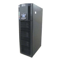
Emerson Liebert CRV User Manual (74 pages)
10-50 kW A/W/C, 50 Hz
Brand:
Emerson
| Category:
Computer Hardware
| Size: 4.52 MB
Table of Contents
Table of Contents
7
Important Safety Instructions
9
Inspection
9
Save These Instructions
9
Operating Limits
10
Noise Level Limits
11
Product Description
12
1 Preliminary Operations
9
Handling
9
2 Positioning - Unit Placement
16
Equipment Inspection
21
Handling the Unit While Packaged
21
Packing Material
21
Recommended Unit Handling Equipment
21
Reference Guide for Receiving, Unpacking, and Preparing for Installation
21
3 UNPACKING and Installation
21
Removing the Unit from the Pallet Using Piano Jacks
22
Unpacking the Unit
22
Removal of Piano Jacks
24
Installation
25
General Layout (Tab. B)
28
4 Refrigeration Connections
28
Refrigeration Pipeline Connections Air
28
Installing Pipelines
29
Pipe Diameter and Thickness
29
Vacuum Creation and Refrigerant Charge
31
R410A Precharge Air - Cooled (A) Units
32
Refrigerant Charge Air
32
Refrigeration Circuits
32
General Warnings
33
5 Water Connections
33
Water Connections - Supply Humidifier and Drain Water (All Units)
33
Chilled Water Connections Water/Glycol - Cooled (W) Units
34
Chilled Water Connections Chilled Water (C) Units - (Fig. K)
35
Notes for Closed Circuit Applications
35
Notes for Open Circuit Applications
35
6 Electrical Connections
37
Protective Features of EC Fan
38
Protective Features of Electrical Heaters
38
Temperature Probes Placed on Racks
38
First Start
42
7 Start-Up
42
Automatic Restart
43
Checking the Refrigeration Piping Pressure Drops
43
Chilled Water Valve Chilled Water (C) Units
43
8 Operation
44
9 Calibrations & Regulation (at Start-- Up)
45
Environment Protection
45
Setting the Thermostatic Expansion Valve
45
Water Leakage Sensor (Liquistat)
45
10 0 Maintenance / Spare Parts
46
Safety Instructions
46
Air Filter Check or Substitution
47
Condensate Drain and Condensate Pump Systems
48
Refrigeration Circuit
49
Oil Topping ---Up of an Installed Circuit
50
Unit Diagnostic
52
Appendix
53
Humidair Humidifier
53
Technical Data Table
57
Installation Drawing
60
Refrigerant, Hydraulic and Electrical Connections
63
Refrigeration & Hydraulic Circuits
68
Advertisement
Advertisement
Related Products
Emerson Liebert Intellislot Unity Card
Emerson Liebert CW
Emerson LiebertChallenger ITR
Emerson Liebert Challenger ITR
Emerson Liebert Precision Cooling
Emerson Liebert.CRV+
Emerson Liebert.CRV+ Series
Emerson Liebert NXr
Emerson Liebert DS/VSWM
Emerson Liebert DS/VSHM
Emerson Categories
Controller
Control Unit
Transmitter
Measuring Instruments
Fan
More Emerson Manuals
Login
Sign In
OR
Sign in with Facebook
Sign in with Google
Upload manual
Upload from disk
Upload from URL