Sign In
Upload
Manuals
Brands
ABB Manuals
Media Converter
ACS880-1607
ABB ACS880-1607 Manuals
Manuals and User Guides for ABB ACS880-1607. We have
1
ABB ACS880-1607 manual available for free PDF download: Hardware Manual
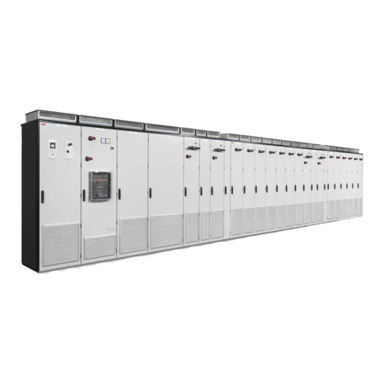
ABB ACS880-1607 Hardware Manual (122 pages)
DC/DC converter units
Brand:
ABB
| Category:
Media Converter
| Size: 19.34 MB
Table of Contents
Table of Contents
5
1 Introduction to the Manual
9
Contents of this Chapter
9
Applicability
9
Safety Instructions
9
Target Audience
9
Contents of the Manual
10
Related Documents
10
Categorization by Frame Size and Option Code
10
Use of Component Designations
10
Terms and Abbreviations
11
2 Operation Principle and Hardware Description
13
Contents of this Chapter
13
Operation Principle
14
Main Circuit Diagram
15
Overview Diagram of a Drive with a Converter Unit
17
Converter Unit Hardware
18
Cabinet Layout
18
R8I DC/DC Converter Module
22
BDCL Filter Module
23
Overview of the Control Connections on the BCU Control Unit
24
DC/DC Converter Control Devices
25
DC Switch/Disconnector (Option +F286)
25
Charging Switch
25
Door Lights
26
ACS-AP-X Control Panel (Option +J400)
26
PC Connection
26
Fieldbus Control
26
Type Designation Labels
27
Type Designation Label of the DC/DC Converter Unit
27
Type Designation Labels of the DC/DC Converter Module
28
Type Designation Label of the BDCL Filter Module
29
Type Designation Keys
30
Type Designation Key of the Converter Unit
30
Type Designation Key of the Converter Module
32
Type Designation Key of the Filter Module
32
3 Mechanical Installation
33
Contents of this Chapter
33
DC/DC Converter Units
33
Energy Storage
33
4 Guidelines for Planning Electrical Installation
35
Contents of this Chapter
35
Limitation of Liability
35
Generic Guidelines
35
Selecting the Energy Storage
36
Disconnection of Energy Storage at the Storage End
37
Implementing Load Current Switch-Off
37
Selecting and Routing the Energy Storage Cables
38
Recommended Cables
38
Typical Cable Sizes
38
Minimizing Electromagnetic Interference
39
Maximum Cable Length
39
EMC Compliance of the Complete Installation
39
Protecting the System against Thermal Overload
39
Protecting the Energy Storage Cable against Short-Circuits
39
5 Electrical Installation
41
Contents of this Chapter
41
Safety
41
Electrical Safety Precautions
42
Static Electricity
43
Optical Components
43
Checking the Insulation of the Energy Storage Cable
43
Connecting the Control Cables for the Converter Unit
44
Default I/O Connection Diagram
44
Connection Procedure of Control Cables
44
Grounding the Outer Shields of the Control Cables at the Cabinet Lead-Through
44
Connecting the Energy Storage Cable and Load Disconnected Indicator Cable
47
Connection Diagram
47
Connection Procedure of the Energy Storage Cables
48
Connection Procedure of the Load Disconnected Indicator Cable
49
Installing Optional Modules
50
Connecting a PC
51
6 Control Unit
53
Contents of this Chapter
53
General
53
Default I/O Connection Diagram
54
External Power Supply for the Control Unit (XPOW)
55
SDHC Memory Card Slot
55
Layout and Connections
56
Control Unit Connector Data
58
Ground Isolation Diagram
60
7 Installation Checklist
61
Contents of this Chapter
61
Warnings
61
Checklist
62
8 Start-Up
63
Contents of this Chapter
63
Start-Up Procedure
64
Safety
64
Checks/Settings with no Voltage Connected
64
Connecting Voltage to the Drive and Converter Control Unit
64
Setting the Parameters
65
Charging the DC/DC Converter and Connecting Voltage to the Converter
65
Connecting the Energy Storage to the DC/DC Converter
65
Testing the DC/DC Converter Operation
65
Disconnecting the DC/DC Converter with DC Switch/Disconnector (Option +F286)
66
Safety
66
Stopping the DC/DC Converter
66
Disconnecting the Energy Storage
66
Disconnecting the DC/DC Converter
66
Working Inside the DC/DC Converter Cubicle
66
Reconnecting the DC/DC Converter with DC Switch/Disconnector (Option +F286)
67
Safety
67
Reconnecting the DC/DC Converter
67
Starting the DC/DC Converter
67
9 Maintenance
69
Contents of this Chapter
69
Maintenance Intervals
70
Maintenance Timers and Counters
71
Cabinet
72
Cleaning the Interior of the Cabinet
72
Cleaning the Door Air Inlets - IP22 and IP42 (Option +B053, +B054)
73
Cleaning the Inlet (Door) Filters - IP54 (Option +B055)
74
Cleaning the Outlet (Roof) Filters (IP54)
74
Power Connections
75
Retightening the Power Connections
75
Fuses
76
Checking and Replacing the DC Fuses
76
Fans
78
Replacing the Cabinet Cooling Fan
78
Replacing the Speed-Controlled Cooling Fan of DC/DC Converter Module
79
Replacing the Direct-On-Line Fan (Option +C188) of the DC/DC Converter Module
81
Replacing the Circuit Board Compartment Fan of the DC/DC Converter Module
83
Replacing the Fan of the BDCL Filter
86
Replacing the Roof Fan for IP54 Cabinet (Option +B055)
87
DC/DC Converter Module
88
Cleaning the Module
88
Replacing the DC/DC Converter Module
89
BDCL Filter
94
Replacing the BDCL Filter
94
Capacitors
98
Reforming the Capacitors
98
Control Panel
99
Replacing the Control Panel Battery
99
Cleaning the Control Panel
99
Control Unit
100
BCU Control Unit Types
100
Memory Unit
100
Control Unit Battery
101
Leds and Other Status Indicators
102
10 Technical Data
103
Contents of this Chapter
103
Ratings
104
Definitions
105
Derating
106
Temperature Derating
106
Altitude Derating
106
Fuses
107
DC Fuses (DC Bus Side)
107
Output DC Fuses (Energy Storage Side)
107
BDCL Filters
108
Dimensions and Weights
109
Free Space Requirements
109
Losses, Cooling Data and Noise
110
Tightening Torques
111
Cable Lugs
111
Electrical Connections
111
Mechanical Connections
111
Insulation Supports
111
Input Power (DC Bus) Connection
112
Output Power (Energy Storage) Connection
112
Control Accuracy - Current and Voltage Control Performance Data
112
Control Unit Connection Data
112
Optical Components
113
Degree of Protection
113
Ambient Conditions
114
Materials
115
Applicable Standards
115
Markings
115
Disclaimer
116
Generic Disclaimer
116
Cybersecurity Disclaimer
116
11 Dimensions
117
What this Chapter Contains
117
Dimension Drawings
118
Frame 1×R8I, Bottom Cable Entry
118
Frame 1×R8I, Top Cable Entry
119
Location and Size of Input Terminals
120
Frame 1×R8I, Bottom Cable Entry
120
Frame 1×R8I, Top Cable Entry
120
Further Information
121
Product and Service Inquiries
121
Product Training
121
Providing Feedback on ABB Drives Manuals
121
Document Library on the Internet
121
Advertisement
Advertisement
Related Products
ABB ACS880-1604
ABB ACS880-1604LC
ABB ACS880-1607LC
ABB ACS880-87LC-4000A/4021A-7
ABB ACS880-87LC-4000A/4132A-7
ABB ACS880-87CC
ABB ACS880-87LC-3200A
ABB ACS880-87LC-3200A-7
ABB ACS880-77CC
ABB ACS800-67LC
ABB Categories
Industrial Equipment
Controller
Measuring Instruments
Battery Charger
DC Drives
More ABB Manuals
Login
Sign In
OR
Sign in with Facebook
Sign in with Google
Upload manual
Upload from disk
Upload from URL