Table of Contents
Advertisement
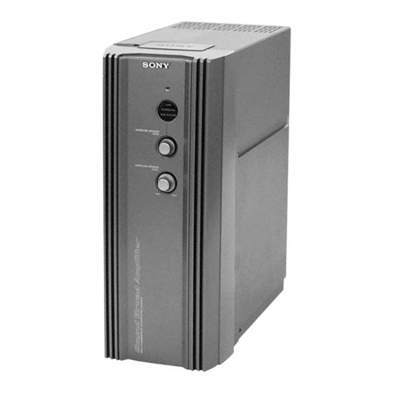
SERVICE MANUAL
Ver 1.0 2001.03
TA-DX80 is the amplifier section in
MHC-DX80, MHC-VX888.
Sony Corporation
9-929-592-11
2001C0500-1
Audio Entertainment Group
C 2001.3
General Engineering Dept.
SPECIFICATIONS
The following measured at AC 120, 220, 240 V 50/60 Hz
DIN power output (rated) 75 + 75 watts
(6 ohms at 1 kHz, DIN)
Continuous RMS power output (reference)
100 + 100 watts
(6 ohms at 1 kHz, 10% THD)
Inputs
MD/VIDEO (AUDIO) IN: voltage 450 mV/250 mV,
(phono jacks)
impedance 47 kilohms
MIC:
sensitivity 1 mV,
(phone jack)
impedance 10 kilohms
Outputs
PHONES:
accepts headphones of
(stereo mini jack)
8 ohms or more
FRONT SPEAKER:
accepts impedance of 6 to 16 ohms
SURROUND SPEAKER: accepts impedance of 6 ohms
General
Power requirements
Mexican models:
120 V AC, 60Hz
E91 models:
220 V AC, 50/60 Hz
Other models:
120 V, 220 V or 230 – 240 V AC, 50/60Hz
Adjustable with voltage selector
Power consumption
180 watts
Approx. 150 × 360 × 343 mm
Dimensions (w/h/d)
Mass:
Approx. 5.5 kg
Design and specifications are subject to change without notice.
• Abbreviation
E91: 220 V AC area in E model
INTEGRATED STEREO AMPLIFIER
TA-DX80
E Model
Advertisement
Table of Contents

Related Manuals for Sony TA-DX80


Summary of Contents for Sony TA-DX80
-
Page 1: Service Manual
TA-DX80 SERVICE MANUAL E Model Ver 1.0 2001.03 TA-DX80 is the amplifier section in MHC-DX80, MHC-VX888. SPECIFICATIONS The following measured at AC 120, 220, 240 V 50/60 Hz DIN power output (rated) 75 + 75 watts (6 ohms at 1 kHz, DIN) -
Page 2: Table Of Contents
LINE WITH MARK 0 ON THE SCHEMATIC DIAGRAMS AND IN THE PARTS LIST ARE CRITICAL TO SAFE OPERATION. REPLACE THESE COMPONENTS WITH SONY PARTS WHOSE PART NUMBERS APPEAR AS SHOWN IN THIS MANUAL OR IN SUPPLEMENTS PUB- LISHED BY SONY. -
Page 3: General
TA-DX80 SECTION 2 This section is extracted from instruction manual. GENERAL • LOCATION OF CONTROLS – Front view – 1 Indicator 2 LINK/SURROUND/SUB WOOFER indicator 3 SURROUND SPEAKER MODE switch 4 SURROUND SPEAKER LEVEL control – Rear view – 1 SYSTEM CONTROL connector... -
Page 4: Disassembly
TA-DX80 SECTION 3 DISASSEMBLY • This set can be disassembled in the order shown below. 3-1. DISASSEMBLY FLOW 3-2. CASE (Page 4) 3-3. FRONT PANEL 3-4. MAIN BOARD SECTION (Page 5) (Page 5) Note: Follow the disassembly procedure in the numerical order given. -
Page 5: Front Panel Section
TA-DX80 SECTION 4 DIAGRAMS 3-3. FRONT PANEL SECTION 4-1. NOTE FOR PRINTED WIRING BOARDS AND SCHEMATIC DIAGRAMS 1 wire (flat type) (15 core) (CN111) Note on Printed Wiring Board: Note on Schematic Diagram: • All capacitors are in µF unless otherwise noted. pF: µµF •... -
Page 6: Printed Wiring Board - Main Board
TA-DX80 4-2. PRINTED WIRING BOARD – MAIN Board – • Semiconductor Location PANEL BOARD (Page 8) CN401 Ref. No. Location MAIN BOARD D201 D202 D231 D251 D252 D301 D302 D321 CN101 D501 SYSTEM CONTROL D552 HCD-DX80 IC101 HCD-VX888 IC111 IC121... -
Page 7: Schematic Diagram - Main Board
TA-DX80 4-3. SCHEMATIC DIAGRAM – MAIN Board – (Page 9) (Page 9) The components identified by mark 0 or dotted line with mark 0 are critical for safety. Replace only with part number specified. -
Page 8: Printed Wiring Boards - Inlet/Panel/Trans Boards
TA-DX80 4-4. PRINTED WIRING BOARDS – INLET/PANEL/TRANS Boards – • Semiconductor Location Ref. No. Location INLET BOARD D401 D402 PANEL BOARD TRANS BOARD D403 D404 D405 D406 VOLTAGE SELECTOR D411 CN601 230- D412 t 220V t 120V R423 240V NO801... -
Page 9: Schematic Diagram - Inlet/Panel/Trans Boards
TA-DX80 4-5. SCHEMATIC DIAGRAM – INLET/PANEL/TRANS Boards – (Page 7) (Page 7) The components identified by mark 0 or dotted line with mark 0 are critical for safety. Replace only with part number specified. -
Page 10: Exploded View
TA-DX80 SECTION 5 SECTION 6 EXPLODED VIEW INLET MAIN ELECTRICAL PARTS LIST NOTE: NOTE: • -XX and -X mean standardized parts, so they • Items marked “*” are not stocked since they The components identified by • Due to standardization, replacements in the •... - Page 11 2SD2525 (TP) (EXCEPT E91) D252 8-719-911-19 DIODE 1SS133T-72 (EXCEPT BR, IA, E91) D252 8-719-991-33 DIODE 1SS133T-77 (BR, IA, E91) Q551 8-729-018-59 TRANSISTOR 2SB1375 (LB-SONY) (E91) Q551 8-729-030-19 TRANSISTOR 2SB1640 (TP) (EXCEPT E91) D301 8-719-911-19 DIODE 1SS133T-72 (EXCEPT BR, IA, E91) D301 8-719-991-33 DIODE 1SS133T-77 (BR, IA, E91) <...
- Page 12 TA-DX80 MAIN PANEL Ref. No. Part No. Description Remark Ref. No. Part No. Description Remark R329 1-249-425-11 CARBON 4.7K 1/4W R162 1-249-419-11 CARBON 1.5K 1/4W R330 1-249-425-11 CARBON 4.7K 1/4W R163 1-247-895-00 CARBON 470K 1/4W R331 1-249-429-11 CARBON 1/4W R165...
- Page 13 TA-DX80 PANEL TRANS Ref. No. Part No. Description Remark Ref. No. Part No. Description Remark < VARIABLE RESISTOR > < CONNECTOR > RV401 1-227-170-11 RES, VAR, CARBON 100K/100K CN401 1-784-737-11 CONNECTOR, FFC 15P (SURROUND SPEAKER LEVEL) < DIODE > < ROTARY ENCODER >...
-
Page 14: Revision History
TA-DX80 REVISION HISTORY Clicking the version allows you to jump to the revised page. Also, clicking the version at the upper right on the revised page allows you to jump to the next revised page. Ver. Date Description of Revision...