
Related Manuals for Siemens RVS41.813


Summary of Contents for Siemens RVS41.813
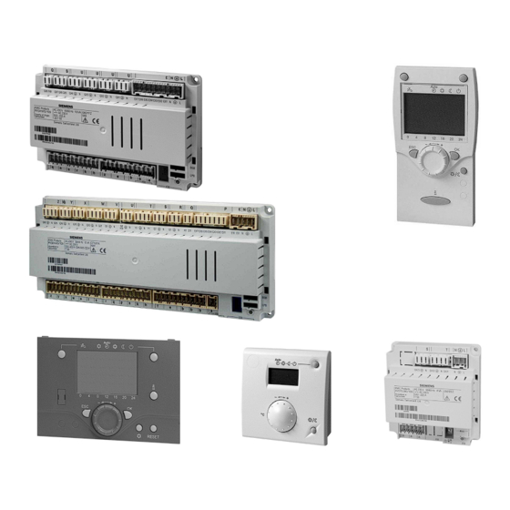
- Page 1 RVS41.813 RVS61.843 AVS75.. AVS37.. QAA75.. Albatros Heat pump controller QAA78.. User manual QAA55.. Edition 2.1 Controller series B Siemens Switzerland Ltd CE1U2355en_02 HVAC Products 28. September 2009...
-
Page 2: Ce1U2355En
ID A6V10084543 (doc) ID A6V10084545 (pdf) 2/258 Siemens Switzerland Ltd User manual RVS61.843, RVS41.813 CE1U2355en_02 HVAC Products 28. September 2009... -
Page 3: Table Of Contents
Mounting method................... 14 Dimensions and drilling plan................15 3.2.1 Connection terminals RVS61.843 ..............16 Terminal markings:RVS41.813..............16 3.2.2 Connection terminals of RVS41.813 ............. 19 Terminal markings RVS41.813..............19 Extension module AVS75.390............... 21 Dimensions and drilling plan................21 3.3.1 Connection terminals AVS75.390..............21 Terminal markings .................. - Page 4 Operation and display ..................80 Heating circuit assignment................82 Room sensor....................82 Device data ....................83 Radio links .....................83 Binding ......................83 List of RF devices ..................83 time programs ....................84 4/258 Siemens Switzerland Ltd User manual RVS61.843, RVS41.813 CE1U2355en_02 HVAC Products Contents 28. September 2009...
- Page 5 Hx pumps ....................110 6.10 Swimming pool .................... 111 Overview...................... 111 Setpoints...................... 111 Priority ......................111 Plant hydraulics ................... 112 6.11 Primary controller / system pump ..............112 5/258 Siemens Switzerland Ltd User manual RVS61.843, RVS41.813 CE1U2355en_02 HVAC Products Contents 28. September 2009...
- Page 6 Overview ......................156 Forced charging ...................156 Automatic locks....................157 Stratification protection ................159 Overtemperature protection .................159 Recooling .....................160 Electric immersion heater ................160 Solar integration...................161 6.18 DHW storage tank..................161 6/258 Siemens Switzerland Ltd User manual RVS61.843, RVS41.813 CE1U2355en_02 HVAC Products Contents 28. September 2009...
- Page 7 Address / power supply ................198 Central functions..................199 Clock......................201 6.22 Errors......................201 Reset ......................201 Error message functions................202 Error history ....................202 7/258 Siemens Switzerland Ltd User manual RVS61.843, RVS41.813 CE1U2355en_02 HVAC Products Contents 28. September 2009...
- Page 8 Plant diagrams .....................226 Basic diagrams ....................226 Legend (catalog of plant diagrams and extra functions) ......241 Technical data....................242 Basic units RVS61.843 and RVS41.813............242 Extension module AVS75.390 ..............243 Operator and room unit AVS37... / QAA7x… / QAA55........244 RF module AVS71.390 ................245 Wireless outside sensor AVS13.399............246...
- Page 9 RF repeater AVS14.390 ................247 Sensor characteristics ................. 248 8.7.1 NTC 1k ......................248 8.7.2 NTC 10k ...................... 249 8.7.3 Pt1000 ......................249 9/258 Siemens Switzerland Ltd User manual RVS61.843, RVS41.813 CE1U2355en_02 HVAC Products Contents 28. September 2009...
-
Page 10: Overview
Ribbon cable for operator unit The following training / demonstration cases are available: KF8921 Demo case for RVS61.843 KF8920 Demo case for RVS41.813 The following products are described in separate pieces of documentation: QAC34 Outside sensor QAD36 Strap-on temperature sensor... -
Page 11: 1.1 Product Range Overview
OCI700 BSB-W Extension module Basic Unit mod. AVS75… RVSxx (max. 2) BSB : Boiler System Bus Basic Unit RVS... LPB : Local Process Bus 11/258 Siemens Switzerland Ltd User manual RVS61.843, RVS41.813 CE1U2355en_02 HVAC Products 1 Overview 28. September 2009... -
Page 12: Operation Options
Basic unit RVS… Room unit QAA75… / 78… / QAA55.. Outside sensor AVS13… Operator unit AVS37.294 (clear text) Operator unit AVS37.390 (basic) RF module AVS71… 12/258 Siemens Switzerland Ltd User manual RVS61.843, RVS41.813 CE1U2355en_02 HVAC Products 1 Overview 28. September 2009... -
Page 13: Safety Notes
"Technical data" must be satisfied • Local regulations (for installation, etc.) must be complied with • Do not open the units. If not observed, warranty becomes void. 13/258 Siemens Switzerland Ltd User manual RVS61.843, RVS41.813 CE1U2355en_02 HVAC Products 2 Safety notes 28. September 2009... -
Page 14: Mounting And Installation
On DIN rail 2359Z11 A: Mounting B: Removal Note: To mount the controller on a DIN rail, a mounting clip is required! 14/258 Siemens Switzerland Ltd User manual RVS61.843, RVS41.813 CE1U2355en_02 HVAC Products 3 Mounting and installation 28. September 2009... -
Page 15: Dimensions And Drilling Plan
Dimensions in mm RVS61.843 RVS41.813 2359Z10 Total height required Dimension X: Connectors with tongues, minimum 70 mm Connector without tongues, minimum 60 mm 15/258 Siemens Switzerland Ltd User manual RVS61.843, RVS41.813 CE1U2355en_02 HVAC Products 3 Mounting and installation 28. September 2009... -
Page 16: Connection Terminals Rvs61.843
Mains connection, protective earth Mains connection, neutral conductor Low-pressure AGP4S.02J/109 High-pressure Multifunctional input EX1 AGP8S.07A/109 Multifunctional input EX2 Multifunctional input EX3 Multifunctional input EX4 16/258 Siemens Switzerland Ltd User manual RVS61.843, RVS41.813 CE1U2355en_02 HVAC Products 3 Mounting and installation 28. September 2009... - Page 17 Extension module AVS75.390 (cable) AVS82.491/109 Operator unit (HMI) (cable) LPB data bus AGP4S.02H/109 LPB ground bus BSB data bus AGP4S.02A/109 BSB ground bus 17/258 Siemens Switzerland Ltd User manual RVS61.843, RVS41.813 CE1U2355en_02 HVAC Products 3 Mounting and installation 28. September 2009...
- Page 18 Multifunctional sensor input BX3 AGP4S.02P/109 Ground Multifunctional sensor input BX4 AGP4S.02R/109 Ground Multifunctional sensor input BX5 AGP4S.02T/109 Ground Multifunctional analog output UX AGP4S.02U/109 Ground 18/258 Siemens Switzerland Ltd User manual RVS61.843, RVS41.813 CE1U2355en_02 HVAC Products 3 Mounting and installation 28. September 2009...
-
Page 19: Connection Terminals Of Rvs41.813
3.2.2 Connection terminals of RVS41.813 071029A RVS41.813/109 000020 Connection diagram Terminal markings RVS41.813 Mains voltage Terminal Connector type Mains connection, live AC 230 V AGP4S.03E/109 Mains connection, protective earth Mains connection, neutral conductor Multifunctional input EX1 Multifunctional input EX2 Multifunctional input EX3 AGP4S.07A/109... - Page 20 AGP4S.02L/109 Ground Evaporator temperature sensor B84/92 AGP4S.02S/109 Source outlet temperature sensor Ground Multifunctional sensor input AGP4S.02F/109 Ground Multifunctional sensor input AGP4S.02K/109 Ground 20/258 Siemens Switzerland Ltd User manual RVS61.843, RVS41.813 CE1U2355en_02 HVAC Products 3 Mounting and installation 28. September 2009...
-
Page 21: Extension Module Avs75.390
AVS83.490/109 connecting cable. The connectors are coded. 3.3.1 Connection terminals AVS75.390 050110A AVS75.390/109 000020 S050110000020 1PAVS75.390/109 = module 1 = module 2 21/258 Siemens Switzerland Ltd User manual RVS61.843, RVS41.813 CE1U2355en_02 HVAC Products 3 Mounting and installation 28. September 2009... -
Page 22: Terminal Markings
• Function extension module 1 (operating line 6020) • Function extension module 2 (6021) are used to define usage of the respective module. 22/258 Siemens Switzerland Ltd User manual RVS61.843, RVS41.813 CE1U2355en_02 HVAC Products 3 Mounting and installation 28. September 2009... -
Page 23: Operator Unit Avs37.294
The AVS37.294 operator unit must be connected to terminal X30 of the basic unit using the AVS82.491/109 connecting cable. The connectors are coded. Dimensions 42.4 Panel cutout (144) 0.5...3.0 23/258 Siemens Switzerland Ltd User manual RVS61.843, RVS41.813 CE1U2355en_02 HVAC Products 3 Mounting and installation 28. September 2009... -
Page 24: 3.5 Operator Unit Avs37.390
The AVS37.390 operator unit must be connected to terminal X30 of the basic unit using the AVS82.491/109 connecting cable. The connectors are coded. Dimensions Control panel, front The AVS37.390 operator unit is a PCB version without casing, supplied by Siemens. 24/258 Siemens Switzerland Ltd User manual RVS61.843, RVS41.813... -
Page 25: 3.6 Room Unit Qaa55
When the unit is removed from its base, power is cut off so that the unit is out of operation. Mounting • The controller must not be exposed to dripping water Connections BSB data BSB ground Dimensions and drilling plan 25/258 Siemens Switzerland Ltd User manual RVS61.843, RVS41.813 CE1U2355en_02 HVAC Products 3 Mounting and installation 28. September 2009... -
Page 26: Room Unit Qaa75
Mounting method Connections Terminal Designation QAA75.610 QAA75.611 BSB data BSB data BSB ground BSB ground Reserved Power supply DC 12 V 26/258 Siemens Switzerland Ltd User manual RVS61.843, RVS41.813 CE1U2355en_02 HVAC Products 3 Mounting and installation 28. September 2009... -
Page 27: Dimensions And Drilling Plan
Dimensions and drilling plan 2359Z12 27/258 Siemens Switzerland Ltd User manual RVS61.843, RVS41.813 CE1U2355en_02 HVAC Products 3 Mounting and installation 28. September 2009... -
Page 28: Rf Components
Radio connection Establishment of the wireless connection is described in the following sections which cover the relevant RF components. Dimensions and drilling plan 28/258 Siemens Switzerland Ltd User manual RVS61.843, RVS41.813 CE1U2355en_02 HVAC Products 3 Mounting and installation 28. September 2009... -
Page 29: Room Unit Qaa78.610
• In the case of wall mounting, there must be sufficient clearance above the unit, enabling it to be fitted and removed Mounting with the base 29/258 Siemens Switzerland Ltd User manual RVS61.843, RVS41.813 CE1U2355en_02 HVAC Products 3 Mounting and installation 28. September 2009... -
Page 30: Connections / Power Supply
Testmode have been received. The test will be ended after 24 telegrams. The test is considered 30/258 Siemens Switzerland Ltd User manual RVS61.843, RVS41.813 CE1U2355en_02 HVAC Products 3 Mounting and installation 28. September 2009... -
Page 31: Dimensions And Drilling Plan
If the test was not successful, some other mounting location should be chosen, or the AVS14.390 RF repeater should be used. Dimensions and drilling plan 2359Z12 31/258 Siemens Switzerland Ltd User manual RVS61.843, RVS41.813 CE1U2355en_02 HVAC Products 3 Mounting and installation 28. September 2009... -
Page 32: Wireless Outside Sensor Avs13.399
The outside sensor is to be connected to the radio transmitter via a 2-core cable, the connections are interchangeable. The device is powered by two 1.5 V alkaline batteries type AAA (LR03). 32/258 Siemens Switzerland Ltd User manual RVS61.843, RVS41.813 CE1U2355en_02 HVAC Products 3 Mounting and installation 28. September 2009... -
Page 33: Radio Connection
After the test, press the button on the transmitter of the wireless outside sensor again briefly until the LED extinguishes. Dimensions and drilling plan 79,8 49,7 Ø 14,1 24,5 49,5 33/258 Siemens Switzerland Ltd User manual RVS61.843, RVS41.813 CE1U2355en_02 HVAC Products 3 Mounting and installation 28. September 2009... -
Page 34: Rf Repeater Avs14.390
10-second intervals. After the test, press the button on the RF repeater again briefly until the LED extinguishes. Dimensions and drilling plan 34/258 Siemens Switzerland Ltd User manual RVS61.843, RVS41.813 CE1U2355en_02 HVAC Products 3 Mounting and installation 28. September 2009... -
Page 35: Checking The Rf Components
To check whether the connections to the required system components are operational, consult menus 130 through 135 on menu "Wireless" (operating level "Commissioning"). 35/258 Siemens Switzerland Ltd User manual RVS61.843, RVS41.813 CE1U2355en_02 HVAC Products 3 Mounting and installation 28. September 2009... -
Page 36: Commissioning
For detailed diagnostics of the plant, check menus "Diagnostics heat generation" and "Diagnostics consumers". 4.1 Heat pump controller Checking the LEDs LED off: No power supply LED on Ready LED blinks Local fault 36/258 Siemens Switzerland Ltd User manual RVS61.843, RVS41.813 CE1U2355en_02 HVAC Products 4 Commissioning 28. September 2009... -
Page 37: Handling
Information display Adopting the setting HP reset and defrost button Quitting the setting Cooling button Adjustment of Comfort setpoint Service socket (BSB) Navigation and settings 37/258 Siemens Switzerland Ltd User manual RVS61.843, RVS41.813 CE1U2355en_02 HVAC Products 5 Handling 28. September 2009... -
Page 38: Display Choices
• Protective functions active • Automatic summer / winter changeover (ECO functions) and automatic 24-hour heating limit inactive in the case of continuous operation with Comfort setpoint 38/258 Siemens Switzerland Ltd User manual RVS61.843, RVS41.813 CE1U2355en_02 HVAC Products 5 Handling 28. September 2009... -
Page 39: Selecting Cooling Mode
• The operating mode is "Off" • Operating mode changeover is effected via H1 or centrally (LPB) • All heating circuits use the holiday function 39/258 Siemens Switzerland Ltd User manual RVS61.843, RVS41.813 CE1U2355en_02 HVAC Products 5 Handling 28. September 2009... -
Page 40: Adjusting The Room Temperature Setpoint
• Possible error messages from the error code list on page 202 • Possible maintenance alarms from the maintenance code list on page 206 • Possible special mode messages 40/258 Siemens Switzerland Ltd User manual RVS61.843, RVS41.813 CE1U2355en_02 HVAC Products 5 Handling 28. September 2009... - Page 41 2 digits after the dot the device address. Hence, 02.01 denotes segment 2, device 1. An error list is given in section "Errors", starting on page 201. 41/258 Siemens Switzerland Ltd User manual RVS61.843, RVS41.813 CE1U2355en_02 HVAC Products 5 Handling 28. September 2009...
-
Page 42: Manual Defrost Of Hp / Reset
This function should not be used in normal operation. When releasing the button, the reset is made after 2 seconds. 42/258 Siemens Switzerland Ltd User manual RVS61.843, RVS41.813 CE1U2355en_02 HVAC Products 5 Handling 28. September 2009... -
Page 43: Programming The Qaa75
Turn the setting knob until the hours of the time of day are correct. Time of day and date Press the OK button to confirm. Hours / minutes 43/258 Siemens Switzerland Ltd User manual RVS61.843, RVS41.813 CE1U2355en_02 HVAC Products 5 Handling 28. September 2009... -
Page 44: User Levels
You are now given a choice of user AUTO levels. Turn the setting knob until the required user level is reached. Enduser Text3 Commissioning Press OK. 44/258 Siemens Switzerland Ltd User manual RVS61.843, RVS41.813 CE1U2355en_02 HVAC Products 5 Handling 28. September 2009... -
Page 45: Setting Structure "End User
Start of summer time Time progr am heating circuit 2 End of summer time Time program heating circuit P Holidays heating circuit 1 Diagnostics of consumers 45/258 Siemens Switzerland Ltd User manual RVS61.843, RVS41.813 CE1U2355en_02 HVAC Products 5 Handling 28. September 2009... -
Page 46: Overview Of The Settings
Room unit 1 Missing ¦ Ready ¦ No recept’n ¦ Change batt Room unit 2 Missing ¦ Ready ¦ No recept’n ¦ Change batt 46/258 Siemens Switzerland Ltd User manual RVS61.843, RVS41.813 CE1U2355en_02 HVAC Products 5 Handling 28. September 2009... - Page 47 Mo - Su ¦ Mo - Fr ¦ Sa - Su ¦ Mo ¦ Tu ¦ We ¦ Th ¦ Fr ¦ Sa ¦Su 1. Phase on 00:00 00:00 24:00 hh:mm 47/258 Siemens Switzerland Ltd User manual RVS61.843, RVS41.813 CE1U2355en_02 HVAC Products 5 Handling 28. September 2009...
- Page 48 − − − / 0 Boost heating °C Quick setback Down to reduced setpoint Off ¦ Down to reduced setpoint ¦ Down to frost prot setpoint 48/258 Siemens Switzerland Ltd User manual RVS61.843, RVS41.813 CE1U2355en_02 HVAC Products 5 Handling 28. September 2009...
- Page 49 Switching differential °C 2-pos Actuator running time Mixing valve in heating mode Open. Control ¦ Open − − − / 10 Lock time dewpoint limiter 49/258 Siemens Switzerland Ltd User manual RVS61.843, RVS41.813 CE1U2355en_02 HVAC Products 5 Handling 28. September 2009...
- Page 50 Floor curing day current °C 1157 I Floor curing days complete 1161 F Excess heat draw Always Off ¦ Heating mode ¦ Always 1170 F With buffer 50/258 Siemens Switzerland Ltd User manual RVS61.843, RVS41.813 CE1U2355en_02 HVAC Products 5 Handling 28. September 2009...
- Page 51 Optg mode changeover Protection None ¦ Protection ¦ Reduced ¦ Comfort ¦ Automatic Domestic hot water 1610 E Nominal setpoint Operating line TempBwMax °C 51/258 Siemens Switzerland Ltd User manual RVS61.843, RVS41.813 CE1U2355en_02 HVAC Products 5 Handling 28. September 2009...
- Page 52 2-pipe system ¦ 4-pipe-system Swimming pool 2055 E Setpoint solar heating °C 2056 E Setpoint source heating °C 2065 F Charging priority solar No ¦ Yes 52/258 Siemens Switzerland Ltd User manual RVS61.843, RVS41.813 CE1U2355en_02 HVAC Products 5 Handling 28. September 2009...
- Page 53 - - - / -30 °C 2911 F For forced buffer storage tank charging Released Locked ¦ Released 2912 F Full charging of buffer storage tank 53/258 Siemens Switzerland Ltd User manual RVS61.843, RVS41.813 CE1U2355en_02 HVAC Products 5 Handling 28. September 2009...
- Page 54 Heat delivered DHW 1 9999999 3124 E Energy brought in heating 1 3500000 3125 E Energy brought in DHW 1 3500000 3127 E Yearly perf factor 2 54/258 Siemens Switzerland Ltd User manual RVS61.843, RVS41.813 CE1U2355en_02 HVAC Products 5 Handling 28. September 2009...
- Page 55 9999999 3171 E Heat delivered DHW 8 9999999 3173 E Energy brought in heating 8 3500000 3174 E Energy brought in DHW 8 3500000 55/258 Siemens Switzerland Ltd User manual RVS61.843, RVS41.813 CE1U2355en_02 HVAC Products 5 Handling 28. September 2009...
- Page 56 − − − / 60 3860 F Evaporation heat carrier °C 3870 F Pump speed min 3871 F Pump speed max 3880 F Antifreeze None 56/258 Siemens Switzerland Ltd User manual RVS61.843, RVS41.813 CE1U2355en_02 HVAC Products 5 Handling 28. September 2009...
- Page 57 With primary controller / system pump No ¦ Yes 5093 F With solar integration No ¦ Yes 5101 F Pump speed min 5102 F Pump speed max 57/258 Siemens Switzerland Ltd User manual RVS61.843, RVS41.813 CE1U2355en_02 HVAC Products 5 Handling 28. September 2009...
- Page 58 Y21 ¦ Air dehumidifier K29 ¦ Heat request K27 ¦ Refrigeration request K28 ¦ Alarm output K10 ¦ Time program 5 K13 58/258 Siemens Switzerland Ltd User manual RVS61.843, RVS41.813 CE1U2355en_02 HVAC Products 5 Handling 28. September 2009...
- Page 59 None ¦ Compressor 2 K2 ¦ Process revers valve Y22 ¦ Hot- gas temp K31 ¦ El imm heater 1 flow K25 ¦ El imm heater 2 59/258 Siemens Switzerland Ltd User manual RVS61.843, RVS41.813 CE1U2355en_02 HVAC Products 5 Handling...
- Page 60 K26 ¦ Div valve cool source Y28 ¦ System pump Q14 ¦ Cascade pump Q25 ¦ Heat gen shutoff valve Y4 ¦ El imm heater DHW K6 ¦ Circulating pump Q4 ¦ St tank transfer 60/258 Siemens Switzerland Ltd User manual RVS61.843, RVS41.813 CE1U2355en_02 HVAC Products 5 Handling 28. September 2009...
- Page 61 HC1 Q2 ¦ Heat circuit pump HC2 Q6 ¦ Heat circuit pump HCP Q20 5930 I Sensor input BX1 DHW sensor B3 None ¦ Buffer sensor B4 ¦ Buffer sensor B41 ¦ Collector 61/258 Siemens Switzerland Ltd User manual RVS61.843, RVS41.813 CE1U2355en_02 HVAC Products 5 Handling 28. September 2009...
- Page 62 Solar flow sensor B63 ¦ Solar return sensor B64 ¦ Buffer sensor B42 ¦ Common flow sensor B10 ¦ Cascade return sensor B70 ¦ Special temp sensor 1 ¦ Special temp sensor 62/258 Siemens Switzerland Ltd User manual RVS61.843, RVS41.813 CE1U2355en_02 HVAC Products 5 Handling 28. September 2009...
- Page 63 HP stage 1 ¦ Swi-on command HP stage 2¦ Pulse count 5961 I Contact type H3 NC ¦ NO 5962 I Function value contact H3 °C 63/258 Siemens Switzerland Ltd User manual RVS61.843, RVS41.813 CE1U2355en_02 HVAC Products 5 Handling 28. September 2009...
- Page 64 None ¦ Electrical utility lock E6 ¦ Low-tariff E5 ¦ Compressor 2 overload E12 ¦ Source overload E14 ¦ Pressure switch source E26 ¦ Flow switch source E15 ¦ 64/258 Siemens Switzerland Ltd User manual RVS61.843, RVS41.813 CE1U2355en_02 HVAC Products 5 Handling 28. September 2009...
- Page 65 K26 ¦ Div valve cool source Y28 ¦ System pump Q14 ¦ Cascade pump Q25 ¦ Heat gen shutoff valve Y4 ¦ El imm heater DHW K6 ¦ Circulating pump Q4 ¦ St tank transfer 65/258 Siemens Switzerland Ltd User manual RVS61.843, RVS41.813 CE1U2355en_02 HVAC Products 5 Handling 28. September 2009...
- Page 66 Q15 ¦ H2 pump Q18 ¦ H3 pump Q19 ¦ Heat circuit pump HCP Q20 ¦ 2nd pump speed HC1 Q21 ¦ 2nd pump speed HC2 Q22 ¦ 2nd pump speed HCP Q23 ¦ Diverting 66/258 Siemens Switzerland Ltd User manual RVS61.843, RVS41.813 CE1U2355en_02 HVAC Products 5 Handling 28. September 2009...
- Page 67 Pressure measurement 10V ¦ Rel room humidity 10V ¦ Room temp 10V ¦ Release swimming pool ¦ Swi-on command HP stage 1 ¦ Swi-on command HP stage 2 67/258 Siemens Switzerland Ltd User manual RVS61.843, RVS41.813 CE1U2355en_02 HVAC Products 5 Handling 28. September 2009...
- Page 68 6204 F Save parameters No ¦ Yes 6205 F Reset to default parameters No ¦ Yes 6212 I Check no. heat source 1 199999 68/258 Siemens Switzerland Ltd User manual RVS61.843, RVS41.813 CE1U2355en_02 HVAC Products 5 Handling 28. September 2009...
- Page 69 History 6 6811 F Error code 6 6812 F History 7 6813 F Error code 7 6814 F History 8 6815 F Error code 8 69/258 Siemens Switzerland Ltd User manual RVS61.843, RVS41.813 CE1U2355en_02 HVAC Products 5 Handling 28. September 2009...
- Page 70 Type of functioning of emergency operation Manually Manually ¦ Automatically − − − − − − / -50 7150 I Simulation outside temp °C 70/258 Siemens Switzerland Ltd User manual RVS61.843, RVS41.813 CE1U2355en_02 HVAC Products 5 Handling 28. September 2009...
- Page 71 Volt 7846 I Contact state H2 Open ¦ Closed 7854 I Voltage signal H3 10.0 Volt 7855 I Contact state H3 Open ¦ Closed 71/258 Siemens Switzerland Ltd User manual RVS61.843, RVS41.813 CE1U2355en_02 HVAC Products 5 Handling 28. September 2009...
- Page 72 History 8 8065 I Setpoint code 8 8066 I History 9 8067 I Setpoint code 9 8068 I History 10 8069 I Setpoint code 10 72/258 Siemens Switzerland Ltd User manual RVS61.843, RVS41.813 CE1U2355en_02 HVAC Products 5 Handling 28. September 2009...
- Page 73 8444 I Remain limit source temp min (0) 1 65535 8446 I Compressor sequence 1-2 ¦ 2-1 8450 F Hours run compressor 1 199'999 73/258 Siemens Switzerland Ltd User manual RVS61.843, RVS41.813 CE1U2355en_02 HVAC Products 5 Handling 28. September 2009...
- Page 74 Outside temp attenuated -50.0 50.0 °C 8704 I Outside temperature composite -50.0 50.0 °C 8720 I Relative room humidity 8721 I Room temperature °C 74/258 Siemens Switzerland Ltd User manual RVS61.843, RVS41.813 CE1U2355en_02 HVAC Products 5 Handling 28. September 2009...
- Page 75 Hours run DHW pump 199'999 8841 F Start counter DHW pump 199'999 8842 F Hours run el DHW 199'999 8843 F Start counter el DHW 199'999 75/258 Siemens Switzerland Ltd User manual RVS61.843, RVS41.813 CE1U2355en_02 HVAC Products 5 Handling 28. September 2009...
- Page 76 Off ¦ On 9054 I Relay output QX22 module 2 Off. Off ¦ On 9055 I Relay output QX23 module 2 Off. Off ¦ On 76/258 Siemens Switzerland Ltd User manual RVS61.843, RVS41.813 CE1U2355en_02 HVAC Products 5 Handling 28. September 2009...
-
Page 77: 5.2 Qaa55
Temperature setpoints per heating program "C omfort setpoint" or "Reduced setpoint" Protective functions active − Automatic summer / winter changeover and automatic 24-hour heating limit active − (ECO functions) 77/258 Siemens Switzerland Ltd User manual RVS61.843, RVS41.813 CE1U2355en_02 HVAC Products 5 Handling 28. September 2009... -
Page 78: Indication Of Cooling Mode
• The occupancy button is only active in automatic operation • The current selection is active until the next switching action according to the heating program takes place 78/258 Siemens Switzerland Ltd User manual RVS61.843, RVS41.813 CE1U2355en_02 HVAC Products 5 Handling 28. September 2009... -
Page 79: Programming
If operation lock is active and one of the locked buttons is pressed, OFF is displayed for 3 seconds. The operation lock does not prevent the service level from being accessed. 79/258 Siemens Switzerland Ltd User manual RVS61.843, RVS41.813 CE1U2355en_02 HVAC Products 5 Handling 28. September 2009... -
Page 80: The Settings In Detail
Programming lock Parameter values can still be displayed, but can no longer be changed if programming lock is activated. 80/258 Siemens Switzerland Ltd User manual RVS61.843, RVS41.813 CE1U2355en_02 HVAC Products 6 The settings in detail 28. September 2009... - Page 81 (Assignment room unit 1) and activated in the basic unit. Room unit 2 The operator unit only supports heating circuit 2. 81/258 Siemens Switzerland Ltd User manual RVS61.843, RVS41.813 CE1U2355en_02 HVAC Products 6 The settings in detail 28. September 2009...
-
Page 82: Heating Circuit Assignment
If only one heating circuit is assigned, the occupancy button always acts on that heating circuit. Room sensor Line no. Operating line Readjustment room sensor The temperature display can be readjusted. 82/258 Siemens Switzerland Ltd User manual RVS61.843, RVS41.813 CE1U2355en_02 HVAC Products 6 The settings in detail 28. September 2009... -
Page 83: Device Data
The radio link to all devices will be cancelled. If radio communication is required again, a new binding must be made. 83/258 Siemens Switzerland Ltd User manual RVS61.843, RVS41.813 CE1U2355en_02 HVAC Products 6 The settings in detail 28. September 2009... -
Page 84: Time Programs
The holiday program is used to switch the heating circuits to a selectable operating level according to calendar dates. Important • The holiday program can only be used in "Automatic" mode 84/258 Siemens Switzerland Ltd User manual RVS61.843, RVS41.813 CE1U2355en_02 HVAC Products 6 The settings in detail 28. September 2009... -
Page 85: Heating Circuits
This is shown in the following graph: TRKmax °C 2358Z01 TRKmax Comfort setpoint max Comfort cooling setpoint Reduced setpoint Frost protection setpoint 85/258 Siemens Switzerland Ltd User manual RVS61.843, RVS41.813 CE1U2355en_02 HVAC Products 6 The settings in detail 28. September 2009... -
Page 86: Heating Curve
It can only be switched on or off. In that case, a readjustment of heating curve slope and parallel displacement is not required. 86/258 Siemens Switzerland Ltd User manual RVS61.843, RVS41.813 CE1U2355en_02 HVAC Products 6 The settings in detail 28. September 2009... -
Page 87: Eco Functions
Example: °C TAged SWHG +1 °C SWHG SWHG -1 °C SWHG Summer/winter heating limit TAged Attenuated outside temperature Temperature Days 87/258 Siemens Switzerland Ltd User manual RVS61.843, RVS41.813 CE1U2355en_02 HVAC Products 6 The settings in detail 28. September 2009... -
Page 88: Flow Temperature Setpoint Limits
TVmax TVmin °C Current flow temperature setpoint TVmax Flow temperature setpoint maximum Tvmin Flow temp setpoint minimum 88/258 Siemens Switzerland Ltd User manual RVS61.843, RVS41.813 CE1U2355en_02 HVAC Products 6 The settings in detail 28. September 2009... -
Page 89: Room Influence
There should be no thermostatic radiator valves in the reference room (mounting location of the room sensor). (If such valves are present, they must be set to their fully open position) 89/258 Siemens Switzerland Ltd User manual RVS61.843, RVS41.813 CE1U2355en_02 HVAC Products 6 The settings in detail 28. September 2009... -
Page 90: Room Temperature Limitation
Boost heating is possible with or without room temperature sensor. °C DTRSA Room temperature setpoint Actual value of the room temperature DTRSA Increase of the room temperature setpoint 90/258 Siemens Switzerland Ltd User manual RVS61.843, RVS41.813 CE1U2355en_02 HVAC Products 6 The settings in detail 28. September 2009... -
Page 91: Quick Setback
The change from one temperature level to the other is optimized in a way that the Comfort setpoint minus 1/4 °C is reached at the respective switching times. 91/258 Siemens Switzerland Ltd User manual RVS61.843, RVS41.813 CE1U2355en_02 HVAC Products 6 The settings in detail... -
Page 92: Raising The Reduced Setpoint
Function "Overtemperature protection for pump circuits" ensures that the energy supply for pump heating circuits corresponds to the demand from the heating curve by activating / deactivating the pump. 92/258 Siemens Switzerland Ltd User manual RVS61.843, RVS41.813 CE1U2355en_02 HVAC Products 6 The settings in detail 28. September 2009... -
Page 93: Mixing Valve Control
If not observed, the floor might get damaged! • The function can be aborted by choosing Off . • Maximum limitation of the flow temperature remains active 93/258 Siemens Switzerland Ltd User manual RVS61.843, RVS41.813 CE1U2355en_02 HVAC Products 6 The settings in detail 28. September 2009... - Page 94 In automatic operating modes, the controller ensures automatic completion of the Temperature profile selected temperature profile. [TVw] [Tag ] Fh + Bh 94/258 Siemens Switzerland Ltd User manual RVS61.843, RVS41.813 CE1U2355en_02 HVAC Products 6 The settings in detail 28. September 2009...
- Page 95 For the manual function, two values of the programmed profile are adopted: The number of functional days represents the sum of functional heating plus floor curing days (Mh=Fh+Bh). 95/258 Siemens Switzerland Ltd User manual RVS61.843, RVS41.813 CE1U2355en_02 HVAC Products 6 The settings in detail 28. September 2009...
-
Page 96: Excess Heat Draw
Select whether the heating circuit shall receive its heat via the primary controller or with system pump the help of the system pump (depending on the type of plant). 96/258 Siemens Switzerland Ltd User manual RVS61.843, RVS41.813 CE1U2355en_02 HVAC Products 6 The settings in detail 28. September 2009... -
Page 97: Remote Control
When using a 4-pipe system, the controller acquires the current room temperature, cooling pipe compares it with the room temperature setpoint and then calculates the required flow 97/258 Siemens Switzerland Ltd User manual RVS61.843, RVS41.813 CE1U2355en_02 HVAC Products 6 The settings in detail 28. September 2009... -
Page 98: Operating Mode
Cooling is enabled in accordance with the heating circuit’s time program Time program 5 / DHW Release of cooling takes place in accordance with time program 5. 98/258 Siemens Switzerland Ltd User manual RVS61.843, RVS41.813 CE1U2355en_02 HVAC Products 6 The settings in detail 28. September 2009... -
Page 99: Cooling Curve
2 or heating circuit P are not taken into consideration. The locking time is aborted by switching the cooling button off and on again. 99/258 Siemens Switzerland Ltd User manual RVS61.843, RVS41.813 CE1U2355en_02 HVAC Products 6 The settings in detail... -
Page 100: Summer Compensation
If there is no valid outside temperature available, the controller uses the value "Flow temp setp min OT = 35 °C". 100/258 Siemens Switzerland Ltd User manual RVS61.843, RVS41.813 CE1U2355en_02 HVAC Products 6 The settings in detail 28. September 2009... -
Page 101: Room Influence
The flow temperature is controlled depending on the room temperature setpoint, the current room temperature and the progression of the room temperature. For example, a 101/258 Siemens Switzerland Ltd User manual RVS61.843, RVS41.813 CE1U2355en_02 HVAC Products 6 The settings in detail... -
Page 102: Room Temperature Limitation
The controller drives the actuator with only one relay output. When the output delivers a signal, the valve opens. When there is no signal, the valve closes automatically. 3-position 102/258 Siemens Switzerland Ltd User manual RVS61.843, RVS41.813 CE1U2355en_02 HVAC Products 6 The settings in detail 28. September 2009... -
Page 103: Dewpoint Monitoring
(947) can be set. The humidity sensor must be assigned to one of the Hx inputs as "Rel room humidity 10V". 103/258 Siemens Switzerland Ltd User manual RVS61.843, RVS41.813 CE1U2355en_02 HVAC Products 6 The settings in detail 28. September 2009... -
Page 104: Buffer Storage Tank / Primary Controller
In the case of external changeover via inputs H1 / H2 / H3, the operating mode to be used can be selected. 104/258 Siemens Switzerland Ltd User manual RVS61.843, RVS41.813 CE1U2355en_02 HVAC Products 6 The settings in detail 28. September 2009... -
Page 105: Frost Protection For The Heating Circuit
DHW storage tank. TWWN TWWmax TWWR °C TWWR Reduced DHW setpoint TWWN Nominal DHW setpoint TWWmax Nominal DHW setpoint maximum 105/258 Siemens Switzerland Ltd User manual RVS61.843, RVS41.813 CE1U2355en_02 HVAC Products 6 The settings in detail 28. September 2009... -
Page 106: Release
Time program 4 / DHW or LT Released when DHW program 4 is set to nominal or the low-tariff input (E5) is active. 106/258 Siemens Switzerland Ltd User manual RVS61.843, RVS41.813 CE1U2355en_02 HVAC Products 6 The settings in detail 28. September 2009... -
Page 107: Charging Priority
Legionella funct weekday Monday…Sunday 1644 Legionella func time 1645 Legionella func setpoint 1646 Legionella funct duration 1647 Legionella funct circ pump 107/258 Siemens Switzerland Ltd User manual RVS61.843, RVS41.813 CE1U2355en_02 HVAC Products 6 The settings in detail 28. September 2009... - Page 108 During the period of time the legionella function is carried out, there is a risk of scalding when opening the taps. 108/258 Siemens Switzerland Ltd User manual RVS61.843, RVS41.813 CE1U2355en_02 HVAC Products 6 The settings in detail 28. September 2009...
-
Page 109: Circulating Pump
The pumps are to be connected to the appropriately defined multifunctional relay outputs Qx.. (6030 - 6032). 109/258 Siemens Switzerland Ltd User manual RVS61.843, RVS41.813 CE1U2355en_02 HVAC Products 6 The settings in detail 28. September 2009... -
Page 110: Hx Pumps
/ system pump and cannot draw any "precontrolled" heating or cooling energy. The heat or refrigeration request is always forwarded to the heat / refrigeration source upstream of the primary controller. 110/258 Siemens Switzerland Ltd User manual RVS61.843, RVS41.813 CE1U2355en_02 HVAC Products 6 The settings in detail 28. September 2009... -
Page 111: 6.10 Swimming Pool
Swimming pool heating through solar charging is given priority. This also applies if storage tank charging priority (3822) would have to give preference to other heat exchangers. 111/258 Siemens Switzerland Ltd User manual RVS61.843, RVS41.813 CE1U2355en_02 HVAC Products 6 The settings in detail 28. September 2009... -
Page 112: Plant Hydraulics
Also, brine-to-water and water-to-water heat pumps can be employed for passive cooling. 112/258 Siemens Switzerland Ltd User manual RVS61.843, RVS41.813 CE1U2355en_02 HVAC Products 6 The settings in detail 28. September 2009... -
Page 113: Function Diagrams
Refrigerant temperature liquid Compressor 1 Evaporator temperature air-to-water HP Compressor 2 Source inlet temperature Fan air-to-water heat pump Source outlet temperature 113/258 Siemens Switzerland Ltd User manual RVS61.843, RVS41.813 CE1U2355en_02 HVAC Products 6 The settings in detail 28. September 2009... -
Page 114: Condenser Pump
However, if activated, frost protection for the plant, the heat pump or the electric immersion heater K25/K26 can still put the condenser pump into operation. 114/258 Siemens Switzerland Ltd User manual RVS61.843, RVS41.813 CE1U2355en_02 HVAC Products 6 The settings in detail... -
Page 115: Source Pump
(2815 or 2816) by at least the "Switching diff source prot" (2817) , enabling the compressor to be switched on when there is a valid heat request. 115/258 Siemens Switzerland Ltd User manual RVS61.843, RVS41.813 CE1U2355en_02 HVAC Products 6 The settings in detail 28. September 2009... -
Page 116: Compressor Control In Plants Without Buffer Or Combi Storage Tank
116/258 Siemens Switzerland Ltd User manual RVS61.843, RVS41.813 CE1U2355en_02 HVAC Products 6 The settings in detail 28. September 2009... -
Page 117: Overview Of Setpoint And Control Sensor Selection
> 0 1°K Off (fault 138) 1°K Off (fault 138) 1°K ±BZ/2 ±BZ/2 > 0 1°K ±BZ/2 ±BZ/2 > 0 1°K 117/258 Siemens Switzerland Ltd User manual RVS61.843, RVS41.813 CE1U2355en_02 HVAC Products 6 The settings in detail 28. September 2009... -
Page 118: Compressor Control In Plants With Buffer Or Combi Storage Tank
The minimum off time is always observed, however, even if the temperature at the upper buffer storage tank sensor drops below the switch-on point. Required sensors: 118/258 Siemens Switzerland Ltd User manual RVS61.843, RVS41.813 CE1U2355en_02 HVAC Products 6 The settings in detail 28. September 2009... -
Page 119: Compressor Settings
The heat pump is switched on again when the temperature at both sensors has dropped by the "Switching diff return temp" (2840) below the maximum switch-off temperature and the minimum off time has elapsed. 119/258 Siemens Switzerland Ltd User manual RVS61.843, RVS41.813 CE1U2355en_02 HVAC Products 6 The settings in detail 28. September 2009... - Page 120 The DHW charge is cancelled when the flow reaches the increased switch off temperature. The compressor 120/258 Siemens Switzerland Ltd User manual RVS61.843, RVS41.813 CE1U2355en_02 HVAC Products 6 The settings in detail...
- Page 121 LP delay on startup When starting the compressor, no consideration is given to the low-pressure switch (E9) during the period of time set here. 121/258 Siemens Switzerland Ltd User manual RVS61.843, RVS41.813 CE1U2355en_02 HVAC Products 6 The settings in detail 28. September 2009...
-
Page 122: Compressor 2
The second stage is released only if, on completion of the second locking time, the actual value to be anticipated lies below the required setpoint. 122/258 Siemens Switzerland Ltd User manual RVS61.843, RVS41.813 CE1U2355en_02 HVAC Products 6 The settings in detail... - Page 123 This means that compressor 1 becomes compressor 2, and vice versa. The current compressor sequence appears on operating line 8446. 123/258 Siemens Switzerland Ltd User manual RVS61.843, RVS41.813 CE1U2355en_02 HVAC Products 6 The settings in detail...
-
Page 124: Electric Immersion Heater In The Flow
• During active limitation due to too low source temperature (see "Time limit source temp min" for water-to-water heat pumps (2822)) 124/258 Siemens Switzerland Ltd User manual RVS61.843, RVS41.813 CE1U2355en_02 HVAC Products 6 The settings in detail 28. September 2009... - Page 125 Electric immersion heater relay K26 Temperature setpoint (switch-on point) Actual value of temperature 2881 Locking time electric flow 2882 Release integr electric flow Time 125/258 Siemens Switzerland Ltd User manual RVS61.843, RVS41.813 CE1U2355en_02 HVAC Products 6 The settings in detail 28. September 2009...
-
Page 126: Heat Pump Protection During Dhw Charging
DHW charging, the controller will not generate a service message. In the case of sudden setpoint changes, the switch-on point changes to setpoint minus the switching differential. 126/258 Siemens Switzerland Ltd User manual RVS61.843, RVS41.813 CE1U2355en_02 HVAC Products 6 The settings in detail 28. September 2009... -
Page 127: General Parameters
If that is not the case, the return sensor (B71) and the return temperature setpoint are used. 127/258 Siemens Switzerland Ltd User manual RVS61.843, RVS41.813 CE1U2355en_02 HVAC Products 6 The settings in detail 28. September 2009... -
Page 128: Heat Pump Protection During Dhw Charging
If the reduced setpoint lies below "DHW charg temp HP min" and the heat pump can terminate DHW charging, the controller will not generate a service message. 128/258 Siemens Switzerland Ltd User manual RVS61.843, RVS41.813 CE1U2355en_02 HVAC Products 6 The settings in detail... - Page 129 . The full charge extends the runtime of the heat pump. 129/258 Siemens Switzerland Ltd User manual RVS61.843, RVS41.813 CE1U2355en_02 HVAC Products 6 The settings in detail 28. September 2009...
-
Page 130: Defrost Function For Air-To-Water Heat Pumps
Defrost release below OT 2971 OEM: Defrost fan above 2972 OEM: Defrost time fan min 2973 OEM: Defrost time fan max 130/258 Siemens Switzerland Ltd User manual RVS61.843, RVS41.813 CE1U2355en_02 HVAC Products 6 The settings in detail 28. September 2009... -
Page 131: Automatic Defrost Function
When, due to icing up during this period of time, the temperature difference (8477) between incoming outside air (B91) and evaporator (B84) exceeds the setpoint (8478), the defrost function is triggered. 131/258 Siemens Switzerland Ltd User manual RVS61.843, RVS41.813 CE1U2355en_02 HVAC Products 6 The settings in detail 28. September 2009... - Page 132 When defrosting with the fan, the defrost time is reached The defrost process at low outside temperatures takes more time than at higher outside temperatures. 132/258 Siemens Switzerland Ltd User manual RVS61.843, RVS41.813 CE1U2355en_02 HVAC Products 6 The settings in detail 28. September 2009...
- Page 133 (see "Duration defrost lock"). The permitted number of defrost attempts is limited by "Numb defrost attempts max" (2958). 133/258 Siemens Switzerland Ltd User manual RVS61.843, RVS41.813 CE1U2355en_02 HVAC Products 6 The settings in detail 28. September 2009...
-
Page 134: Frost Protection For The Heat Pump
The HP partial plant diagram must support passive cooling (HP 14, 15, 22, 23, 34, 35, 42, 43). Passive cooling is not possible with air-to-water heat pumps. 134/258 Siemens Switzerland Ltd User manual RVS61.843, RVS41.813 CE1U2355en_02 HVAC Products 6 The settings in detail 28. September 2009... - Page 135 If passive cooling is effected via the heating / cooling pipe, parameter "In passive cooling mode" (3007) can be used to define whether the condenser pump shall be switched on or off. 135/258 Siemens Switzerland Ltd User manual RVS61.843, RVS41.813 CE1U2355en_02 HVAC Products 6 The settings in detail 28. September 2009...
-
Page 136: During Compressor Operation
SD ch’over cooling pas/act 136/258 Siemens Switzerland Ltd User manual RVS61.843, RVS41.813 CE1U2355en_02 HVAC Products 6 The settings in detail 28. September 2009... -
Page 137: Sensor Calibration
The deviation of both sensors and the required correction value should normally be < 1°K and cannot exceed 2°K. 137/258 Siemens Switzerland Ltd User manual RVS61.843, RVS41.813 CE1U2355en_02 HVAC Products 6 The settings in detail 28. September 2009... -
Page 138: Readj Hp Return Sensor
The menu Input / output test displays the measured sensor values without readjustment. The readjusted temperature values used for control are displayed in the menu Diagnostics heat generation . 138/258 Siemens Switzerland Ltd User manual RVS61.843, RVS41.813 CE1U2355en_02 HVAC Products 6 The settings in detail 28. September 2009... -
Page 139: 6.13 Energy Meter
The functionality for recording used/delivered energy and the calculation of yearly performance as described here and implemented on the device is based on the following model: 139/258 Siemens Switzerland Ltd User manual RVS61.843, RVS41.813 CE1U2355en_02 HVAC Products 6 The settings in detail 28. September 2009... - Page 140 [l/h] and the actual runtime/rpms, measurement of temperature difference on the heat pump flow (B21) and return (B71) and calculation of heat volume. 140/258 Siemens Switzerland Ltd User manual RVS61.843, RVS41.813 CE1U2355en_02 HVAC Products 6 The settings in detail 28. September 2009...
-
Page 141: Heat Volume Meter
Pusle valency = (numerator / denominator) * unit 141/258 Siemens Switzerland Ltd User manual RVS61.843, RVS41.813 CE1U2355en_02 HVAC Products 6 The settings in detail 28. September 2009... -
Page 142: Flow Heating
The function must be switched off via both parameters ("---") if metering of heating energy via volume calculations is not desired. 142/258 Siemens Switzerland Ltd User manual RVS61.843, RVS41.813 CE1U2355en_02 HVAC Products 6 The settings in detail 28. September 2009... -
Page 143: Energy Counter Electricity/Natural Gas
Pulse unit energy = kWh The pulse or its energy value is added directly in the counter for employed energy. 143/258 Siemens Switzerland Ltd User manual RVS61.843, RVS41.813 CE1U2355en_02 HVAC Products 6 The settings in detail 28. September 2009... -
Page 144: Counter/Performance Factor
Internal to the controller, delivered heat for heating and DHW are recorded separately, but only the total value is displayed. They are, however, listed separately in the fixed day storage (Par. 3120-3188) 144/258 Siemens Switzerland Ltd User manual RVS61.843, RVS41.813 CE1U2355en_02 HVAC Products 6 The settings in detail 28. September 2009... -
Page 145: Fixed Day Storage (Yearly Performance Factor)
The underlying, annual energy values are stored – separately for heating and DHW heating – for any consumption or plant analysis. 145/258 Siemens Switzerland Ltd User manual RVS61.843, RVS41.813 CE1U2355en_02 HVAC Products 6 The settings in detail 28. September 2009... - Page 146 ) and employed energy (E ) over a period of one year. The gain consists for the energy derived from the environment (E 146/258 Siemens Switzerland Ltd User manual RVS61.843, RVS41.813 CE1U2355en_02 HVAC Products 6 The settings in detail 28. September 2009...
- Page 147 If the passive cooling mode is active as of the brine circuit. In cooling mode: Energy acquisition is not counted Energy supply is not counted 147/258 Siemens Switzerland Ltd User manual RVS61.843, RVS41.813 CE1U2355en_02 HVAC Products 6 The settings in detail 28. September 2009...
-
Page 148: 6.14 Cascade
The heat sources are switched on and off in the order of their LPB device addresses. Order according to the number of operating hours 148/258 Siemens Switzerland Ltd User manual RVS61.843, RVS41.813 CE1U2355en_02 HVAC Products 6 The settings in detail... -
Page 149: Electric Immersion Heaters In The Cascade
149/258 Siemens Switzerland Ltd User manual RVS61.843, RVS41.813 CE1U2355en_02 HVAC Products 6 The settings in detail... -
Page 150: Supplementary Source (Only Rvs41
In this case, the decisive criterion is the difference by which the temperature lies above or below the common flow temperature setpoint. 150/258 Siemens Switzerland Ltd User manual RVS61.843, RVS41.813 CE1U2355en_02 HVAC Products 6 The settings in detail... - Page 151 No consideration is given to the locking time, if the heat pump malfunctions or is locked, or if the supplementary source must end DHW charging. The function can be deactivated. 151/258 Siemens Switzerland Ltd User manual RVS61.843, RVS41.813 CE1U2355en_02 HVAC Products 6 The settings in detail 28. September 2009...
-
Page 152: 6.16 Solar
Temperature differential on SdOff Temperature differential off Storage tank temperature TLmin Charging temp min DHW storage tank / buffer / swimming pool 152/258 Siemens Switzerland Ltd User manual RVS61.843, RVS41.813 CE1U2355en_02 HVAC Products 6 The settings in detail 28. September 2009... -
Page 153: Priority
If the parameter is deactivated (---), priority always follows the settings "Charging priority storage tank". 153/258 Siemens Switzerland Ltd User manual RVS61.843, RVS41.813 CE1U2355en_02 HVAC Products 6 The settings in detail 28. September 2009... -
Page 154: Start Function
If there is a risk of overtemperature at the collector, storage tank charging is continued to reduce the amount of excess heat. When the storage tank’s safety temperature is reached, charging is stopped. 154/258 Siemens Switzerland Ltd User manual RVS61.843, RVS41.813 CE1U2355en_02 HVAC Products 6 The settings in detail 28. September 2009... -
Page 155: Medium's Evaporation Temperature
Since the mixing ratio of the collector medium has an impact on heat transmission, the type of antifreeze used and its concentration must be entered in order to be able to determine the energy yield. 155/258 Siemens Switzerland Ltd User manual RVS61.843, RVS41.813 CE1U2355en_02 HVAC Products 6 The settings in detail 28. September 2009... -
Page 156: 6.17 Buffer Storage Tank
(4709) and "Forced charg setp heat max" (4710). Forced charging can be triggered either via low-tariff input E5 or operating line "Forced charging time" (4711). 156/258 Siemens Switzerland Ltd User manual RVS61.843, RVS41.813 CE1U2355en_02 HVAC Products 6 The settings in detail 28. September 2009... -
Page 157: Automatic Locks
Line no. Operating line 4720 Auto generation lock None With B4 With B4 and B41 / B42 4722 Temp diff buffer/HC 157/258 Siemens Switzerland Ltd User manual RVS61.843, RVS41.813 CE1U2355en_02 HVAC Products 6 The settings in detail 28. September 2009... - Page 158 The heat source is released as soon as the temperature at both buffer storage tank sensors drops by "Temp diff buffer/HC" plus 1 K below the required flow temperature. 158/258 Siemens Switzerland Ltd User manual RVS61.843, RVS41.813 CE1U2355en_02 HVAC Products 6 The settings in detail...
-
Page 159: Stratification Protection
The protective collector overtemperature function can reactivate the collector pump until the maximum storage tank temperature is reached. 159/258 Siemens Switzerland Ltd User manual RVS61.843, RVS41.813 CE1U2355en_02 HVAC Products 6 The settings in detail 28. September 2009... -
Page 160: Recooling
Electric immersion heater K16 is not used for forced charging. 160/258 Siemens Switzerland Ltd User manual RVS61.843, RVS41.813 CE1U2355en_02 HVAC Products 6 The settings in detail 28. September 2009... -
Page 161: Solar Integration
Storage tank charging can be effected with one or 2 sensors. It is also possible to implement charging with one sensor and the legionella function with 2 sensors (setting 3). 161/258 Siemens Switzerland Ltd User manual RVS61.843, RVS41.813 CE1U2355en_02 HVAC Products 6 The settings in detail 28. September 2009... -
Page 162: Overtemperature Protection
Legionella function + switching differential when using the Legionella function. 162/258 Siemens Switzerland Ltd User manual RVS61.843, RVS41.813 CE1U2355en_02 HVAC Products 6 The settings in detail 28. September 2009... -
Page 163: Recooling
For the DHW to be heated, the DHW operating mode button must be pressed. 163/258 Siemens Switzerland Ltd User manual RVS61.843, RVS41.813 CE1U2355en_02 HVAC Products 6 The settings in detail 28. September 2009... -
Page 164: Excess Heat Draw
When dissipation of excess heat is activated, it can be drawn by space heating. This can be selected separately for each heating circuit. 164/258 Siemens Switzerland Ltd User manual RVS61.843, RVS41.813 CE1U2355en_02 HVAC Products 6 The settings in detail 28. September 2009... -
Page 165: Plant Hydraulics
The controller calculates the charging pump speed required to ensure that the DHW setpoint + charging increase acquired by sensor B35 is achieved. 165/258 Siemens Switzerland Ltd User manual RVS61.843, RVS41.813 CE1U2355en_02 HVAC Products 6 The settings in detail 28. September 2009... - Page 166 If no B36 is connected, sensor B35 is used to make the calculation. If no valid sensor is connected, the pump will not be speed-controlled. 166/258 Siemens Switzerland Ltd User manual RVS61.843, RVS41.813 CE1U2355en_02 HVAC Products 6 The settings in detail...
-
Page 167: Transfer
(left) or the mixing valve (right) tries to reach or maintain the nominal setpoint minus the setting of parameter 5406 at sensor B38. As soon as the flow switch detects no more 167/258 Siemens Switzerland Ltd User manual RVS61.843, RVS41.813 CE1U2355en_02 HVAC Products 6 The settings in detail... -
Page 168: 6.20 Configuration
After that, select the extra functions and make the fine-tuning via the operating lines of the individual parameters. 168/258 Siemens Switzerland Ltd User manual RVS61.843, RVS41.813 CE1U2355en_02 HVAC Products 6 The settings in detail 28. September 2009... -
Page 169: Preselection Of Plant Diagram
Overtemperature protection deactivated 4-pipe system The cooling and heating circuits draw their cooling / heating energy from separate Y23/Y24 circuits. Y1/Y2 169/258 Siemens Switzerland Ltd User manual RVS61.843, RVS41.813 CE1U2355en_02 HVAC Products 6 The settings in detail 28. September 2009... -
Page 170: Heating Circuit 2
Heating circuit 2 Off ¦ On Heating circuit 2 Using this setting, heating circuit 2 can be switched on and off. 170/258 Siemens Switzerland Ltd User manual RVS61.843, RVS41.813 CE1U2355en_02 HVAC Products 6 The settings in detail 28. September 2009... -
Page 171: Dhw Controlling Element Q3
The separate circuit is switched on. DHW charging takes place solely via the heat source selected for it. For the separate circuit, DHW controlling element Q3 must be set to "Diverting valve"! 171/258 Siemens Switzerland Ltd User manual RVS61.843, RVS41.813 CE1U2355en_02 HVAC Products 6 The settings in detail 28. September 2009... -
Page 172: Heat Pump
When using a heat source with external control. The external heat pump can be controlled via the Hx outputs (on / off). Connection of heat pump sensors to the Siemens controller is optional. Sensors connected to the controller are used and the associated functions are enabled. -
Page 173: Solar
DHW and as a buffer storage tank, or exclusively for one of the two. 173/258 Siemens Switzerland Ltd User manual RVS61.843, RVS41.813 CE1U2355en_02 HVAC Products 6 The settings in detail 28. September 2009... -
Page 174: Buffer Storage Tank
2. 2nd pump speed HCP Q23 Diverting valve cooling Y21 Air dehumidifier K29 Heat request K27 Refrigeration request K28 Alarm output K10 Time program 5 K13 174/258 Siemens Switzerland Ltd User manual RVS61.843, RVS41.813 CE1U2355en_02 HVAC Products 6 The settings in detail 28. September 2009... - Page 175 The relay is used for the control of the second stage of an electric immersion heater in the flow (K26). Diverting valve cool strat2 Y28 175/258 Siemens Switzerland Ltd User manual RVS61.843, RVS41.813 CE1U2355en_02 HVAC Products 6 The settings in detail 28. September 2009...
- Page 176 Collector pump 2 Q16 For control of the circulating pump of a second solar collector circuit. Solar pump external exchanger K9 176/258 Siemens Switzerland Ltd User manual RVS61.843, RVS41.813 CE1U2355en_02 HVAC Products 6 The settings in detail 28. September 2009...
- Page 177 Reduced mode (e.g. during night setback). In that case, after pump speed 1, pump speed 2 is switched on as follows via "Multifunctional relay RX": 177/258 Siemens Switzerland Ltd User manual RVS61.843, RVS41.813 CE1U2355en_02 HVAC Products 6 The settings in detail 28. September 2009...
- Page 178 5 (601 – 616). Heating circuit pump HC1 Q2 The relay is used for the control of heating circuit pump Q2. 178/258 Siemens Switzerland Ltd User manual RVS61.843, RVS41.813 CE1U2355en_02 HVAC Products 6 The settings in detail 28. September 2009...
-
Page 179: Function Output Qx4-Mod
Solar return sensor B64 Buffer sensor B42 Common flow sensor B10 Cascade return sensor B70 Solar temp sensor 1 Solar temp sensor 2 179/258 Siemens Switzerland Ltd User manual RVS61.843, RVS41.813 CE1U2355en_02 HVAC Products 6 The settings in detail 28. September 2009... -
Page 180: Input H1, H3
5954, Function value 1 H1, H3 5964 5955, Voltage value 2 H1, H3 5965 5956, Function value 2 H1, H3 5966 180/258 Siemens Switzerland Ltd User manual RVS61.843, RVS41.813 CE1U2355en_02 HVAC Products 6 The settings in detail 28. September 2009... - Page 181 2 fixed points (voltage value 1 / function value 1, and voltage value 2 / function value Pressure measurement 10V 181/258 Siemens Switzerland Ltd User manual RVS61.843, RVS41.813 CE1U2355en_02 HVAC Products 6 The settings in detail 28. September 2009...
- Page 182 Configuration: Set the function of input Hx to "Release swimming pool". For a description of the function, refer to operating line 2065 "Charging priority solar". 182/258 Siemens Switzerland Ltd User manual RVS61.843, RVS41.813 CE1U2355en_02 HVAC Products 6 The settings in detail...
- Page 183 (heating circuit pumps, DHW pump, electrical immersion heat in the storage tank, etc) is counted as well. 183/258 Siemens Switzerland Ltd User manual RVS61.843, RVS41.813 CE1U2355en_02 HVAC Products 6 The settings in detail 28. September 2009...
- Page 184 TVLw [°C] =130 Hx [V] 0.15 V =10V TVLw Flow temperature setpoint Voltage value at Hx Voltage value 1 Function value 1 184/258 Siemens Switzerland Ltd User manual RVS61.843, RVS41.813 CE1U2355en_02 HVAC Products 6 The settings in detail 28. September 2009...
- Page 185 Function value 1 Voltage value 2 Function value 2 If the measured value lies below 0.15 V, it is regarded invalid. 185/258 Siemens Switzerland Ltd User manual RVS61.843, RVS41.813 CE1U2355en_02 HVAC Products 6 The settings in detail 28. September 2009...
-
Page 186: Input Ex1, Ex2, Ex3, Ex4, Ex5, Ex6, Ex7
If overload protection responds several times within the preset "Duration error repetition", the heat pump initiates lockout and must be manually reset to resume operation. 186/258 Siemens Switzerland Ltd User manual RVS61.843, RVS41.813 CE1U2355en_02 HVAC Products 6 The settings in detail 28. September 2009... - Page 187 In the event of an active fault, the controller switches off both compressors. When the fault status message is no longer present, the heat pump is released again. 187/258 Siemens Switzerland Ltd User manual RVS61.843, RVS41.813 CE1U2355en_02 HVAC Products 6 The settings in detail...
-
Page 188: Mixing Group
Logical assignment of sensors and relays per mixing group function 188/258 Siemens Switzerland Ltd User manual RVS61.843, RVS41.813 CE1U2355en_02 HVAC Products 6 The settings in detail 28. September 2009... -
Page 189: Extension Module
(see page 97). Frost protection for the plant (see page 194) also acts on the heating circuit of the extension module. 189/258 Siemens Switzerland Ltd User manual RVS61.843, RVS41.813 CE1U2355en_02 HVAC Products 6 The settings in detail 28. September 2009... -
Page 190: Qx Extension Module
Air dehumidifier K29 DHW controlling element Q3 Supplementary source control Heat request K27 Refrigeration request K28 Alarm output K10 Time program 5 K13 190/258 Siemens Switzerland Ltd User manual RVS61.843, RVS41.813 CE1U2355en_02 HVAC Products 6 The settings in detail 28. September 2009... -
Page 191: Bx Extension Module
The settings for input H2 on the extension module are the same as those for the Hx inputs on the basic unit. They are described under operating line "Function input Hx". 191/258 Siemens Switzerland Ltd User manual RVS61.843, RVS41.813 CE1U2355en_02 HVAC Products 6 The settings in detail... -
Page 192: 10V Output Ux
(PWM). This operating line is used to define the maximum temperature request Temp value 10V UX (corresponding to 10 V). 192/258 Siemens Switzerland Ltd User manual RVS61.843, RVS41.813 CE1U2355en_02 HVAC Products 6 The settings in detail 28. September 2009... -
Page 193: Types Of Sensor / Readjustment
Setting 0: Function switched off. The attenuated as well as mixed temperature are the same as the present outside air temperature. 193/258 Siemens Switzerland Ltd User manual RVS61.843, RVS41.813 CE1U2355en_02 HVAC Products 6 The settings in detail 28. September 2009... -
Page 194: Frost Protection For The Plant
If the relative humidity falls by the switching differential set here below "Air dehumidifier r.h. on", the dehumidifier is switched off again. 194/258 Siemens Switzerland Ltd User manual RVS61.843, RVS41.813 CE1U2355en_02 HVAC Products 6 The settings in detail 28. September 2009... -
Page 195: Sensors
Buffer storage tank DHW storage tank 6217 Check no. heating circuit Heating circuit P Heating circuit 2 Heating circuit 1 195/258 Siemens Switzerland Ltd User manual RVS61.843, RVS41.813 CE1U2355en_02 HVAC Products 6 The settings in detail 28. September 2009... - Page 196 Check no. heat source 1 No solar TWW/P TWW+P TWW/P TWW/P TWW/P TWW+P TWW/P TWW/P TWW+P TWW/P TWW/P TWW/P TWW+P TWW/P 196/258 Siemens Switzerland Ltd User manual RVS61.843, RVS41.813 CE1U2355en_02 HVAC Products 6 The settings in detail 28. September 2009...
- Page 197 14..16 Heating/cooling, 4-pipe, separate distribution 20..27 Heating/cooling, 2-pipe, separate distribution 30..38 Heating/cooling, 4-pipe, separate distribution 40..42 Cooling only, 4-pipe 197/258 Siemens Switzerland Ltd User manual RVS61.843, RVS41.813 CE1U2355en_02 HVAC Products 6 The settings in detail 28. September 2009...
-
Page 198: Device Data
Both the device address and the segment address consist of 2-digit numbers. segment address Together, they form the device’s unambiguous LPB address (e.g. 14.16 stands for segment 14, device 16). 198/258 Siemens Switzerland Ltd User manual RVS61.843, RVS41.813 CE1U2355en_02 HVAC Products 6 The settings in detail 28. September 2009... -
Page 199: Central Functions
"Action changeover functions", either the heating circuits in the segment or those of the entire system are switched based on operating line 730. 199/258 Siemens Switzerland Ltd User manual RVS61.843, RVS41.813 CE1U2355en_02 HVAC Products 6 The settings in detail 28. September 2009... - Page 200 The Ecobit from the external generator is not observed. Note: If an LMU control (slave) is connected as an additional generator, the parameter must be set to "No"! 200/258 Siemens Switzerland Ltd User manual RVS61.843, RVS41.813 CE1U2355en_02 HVAC Products 6 The settings in detail 28. September 2009...
-
Page 201: Clock
Pending error messages from the heat pump are reset with this operating line. The preset switch-on delay is bridged, thus avoiding undesirable waiting times during commissioning or fault tracing. 201/258 Siemens Switzerland Ltd User manual RVS61.843, RVS41.813 CE1U2355en_02 HVAC Products 6 The settings in detail 28. September 2009... -
Page 202: Error Message Functions
Manual reset In the case of error displays on the info level where "Reset?" appears, the error can be manually reset. 202/258 Siemens Switzerland Ltd User manual RVS61.843, RVS41.813 CE1U2355en_02 HVAC Products 6 The settings in detail 28. September 2009... - Page 203 B81 6 1 (installer) 37: Hot-gas sensor 2 B82 6 1 (installer) 38: Flow sensor prim B15 6 1 (installer) controller 203/258 Siemens Switzerland Ltd User manual RVS61.843, RVS41.813 CE1U2355en_02 HVAC Products 6 The settings in detail 28. September 2009...
- Page 204 226: Compressor 1 Numb Compressor 1 2 (customer E11 9 overloaded overloaded service) 227: Compressor 2 E12 9 Numb Compressor 2 2 (customer 204/258 Siemens Switzerland Ltd User manual RVS61.843, RVS41.813 CE1U2355en_02 HVAC Products 6 The settings in detail 28. September 2009...
- Page 205 Number* These plant states do not directly lead to an error message, but first deliver a status message upon initial startup. 205/258 Siemens Switzerland Ltd User manual RVS61.843, RVS41.813 CE1U2355en_02 HVAC Products 6 The settings in detail 28. September 2009...
-
Page 206: 6.23 Service / Special Operation
Max starts compr1/hrs run Cur starts compr1/hrs run Average number of starts of compressor 1 per hour run, reached over the last 6 weeks. 206/258 Siemens Switzerland Ltd User manual RVS61.843, RVS41.813 CE1U2355en_02 HVAC Products 6 The settings in detail 28. September 2009... - Page 207 15: Diff evap max (priority 3) Reset This parameter can be reset, provided the respective access right is granted. 207/258 Siemens Switzerland Ltd User manual RVS61.843, RVS41.813 CE1U2355en_02 HVAC Products 6 The settings in detail 28. September 2009...
-
Page 208: Other Maintenance Messages
"Economy function", the enduser can switch off the heat pump or the electrical immersion heater for any desired period of time. 208/258 Siemens Switzerland Ltd User manual RVS61.843, RVS41.813 CE1U2355en_02 HVAC Products 6 The settings in detail 28. September 2009... -
Page 209: Emergency Operation
During simulation, calculation of the 3 mentioned outside temperatures continues and the temperatures are available again when simulation is completed. 209/258 Siemens Switzerland Ltd User manual RVS61.843, RVS41.813 CE1U2355en_02 HVAC Products 6 The settings in detail 28. September 2009... -
Page 210: Manual Defrost
When selecting a setting from the relay test, the relevant relay is energized, thus putting the connected component into operation. The correct functioning of the relays and correct wiring can thus be tested. 210/258 Siemens Switzerland Ltd User manual RVS61.843, RVS41.813 CE1U2355en_02 HVAC Products 6 The settings in detail 28. September 2009... -
Page 211: Output Test Ux
The selected sensor values are updated within a maximum of 5 seconds. The display is made with no measured value correction. 211/258 Siemens Switzerland Ltd User manual RVS61.843, RVS41.813 CE1U2355en_02 HVAC Products 6 The settings in detail 28. September 2009... -
Page 212: Input Test E
Input EX 6 7917 Input EX 7 By selecting a setting from input test E, the relevant input will be displayed, enabling checking. 212/258 Siemens Switzerland Ltd User manual RVS61.843, RVS41.813 CE1U2355en_02 HVAC Products 6 The settings in detail 28. September 2009... -
Page 213: 6.25 State Of Plant
Draw-off mode Draw-off mode Recooling via collector Recooling via DHW/HCs Recooling active Discharging protection active Charging time limitation active DHW charging locked 213/258 Siemens Switzerland Ltd User manual RVS61.843, RVS41.813 CE1U2355en_02 HVAC Products 6 The settings in detail 28. September 2009... - Page 214 3-ph curr asymmetrical Low-pressure Fan overload Compressor 1 overload Compressor 2 overload Source pump overload Flow switch consumers Limit OT min 214/258 Siemens Switzerland Ltd User manual RVS61.843, RVS41.813 CE1U2355en_02 HVAC Products 6 The settings in detail 28. September 2009...
- Page 215 Charging buffer storage tank Charg swimm pool Charg swimm pool Min charg temp not reached Temp diff insufficient Radiation insufficient Radiation insufficient 215/258 Siemens Switzerland Ltd User manual RVS61.843, RVS41.813 CE1U2355en_02 HVAC Products 6 The settings in detail 28. September 2009...
- Page 216 In operation for heating circuit In operation for heating circuit Released for HC Released for HC Overrun active Overrun active Off. Off. 216/258 Siemens Switzerland Ltd User manual RVS61.843, RVS41.813 CE1U2355en_02 HVAC Products 6 The settings in detail 28. September 2009...
-
Page 217: History
The display of 0 indicates that the relevant component is currently off. The display of 1 indicates that the relevant component is currently on. 217/258 Siemens Switzerland Ltd User manual RVS61.843, RVS41.813 CE1U2355en_02 HVAC Products 6 The settings in detail 28. September 2009... -
Page 218: Setpoints And Actual Values
First, compressor 1 is put into operation, then compressor 2. 2 – 1 First, compressor 2 is put into operation, then compressor 1. 218/258 Siemens Switzerland Ltd User manual RVS61.843, RVS41.813 CE1U2355en_02 HVAC Products 6 The settings in detail 28. September 2009... -
Page 219: Time / Start Counter
This shows – after a successful or unsuccessful defrost process – how long the defrost function is locked until a new defrost attempt may be made / new defrost process may be carried out. 219/258 Siemens Switzerland Ltd User manual RVS61.843, RVS41.813 CE1U2355en_02 HVAC Products 6 The settings in detail 28. September 2009... -
Page 220: Solar
1, 2 / DHW Display of the temperature difference between collector sensor B6 / B61 and DHW sensors B3 and B31. 220/258 Siemens Switzerland Ltd User manual RVS61.843, RVS41.813 CE1U2355en_02 HVAC Products 6 The settings in detail 28. September 2009... -
Page 221: 6.28 Diagnostics Consumers
The attenuated outside temperature can be reset directly on operating line 8703 (reset) . Room Line no. Operating line 8720 Relative room humidity 8721 Room temperature 8722 Dewpoint temp 1 221/258 Siemens Switzerland Ltd User manual RVS61.843, RVS41.813 CE1U2355en_02 HVAC Products 6 The settings in detail 28. September 2009... -
Page 222: Heating Circuits 1, 2, P
The room temperature setpoint for cooling is displayed on operating line 8741. 222/258 Siemens Switzerland Ltd User manual RVS61.843, RVS41.813 CE1U2355en_02 HVAC Products 6 The settings in detail 28. September 2009... -
Page 223: Domestic Hot Water
Line no. Operating line 8970 Electrical immersion heater buffer K16 Off. 8980 Buffer temp 1 8981 Buffer setpoint 8982 Buffer temp 2 223/258 Siemens Switzerland Ltd User manual RVS61.843, RVS41.813 CE1U2355en_02 HVAC Products 6 The settings in detail 28. September 2009... -
Page 224: Input H1
Display of "Off" means that the plant component assigned to the output is currently off. "On" means that the relevant plant component is presently in operation. 224/258 Siemens Switzerland Ltd User manual RVS61.843, RVS41.813 CE1U2355en_02 HVAC Products 6 The settings in detail 28. September 2009... -
Page 225: 6.29 Pump Kick
Cooling circuit mixing valve closed Diverting valve cooling Hx group Pump H1 Pump H2 Pump H3 225/258 Siemens Switzerland Ltd User manual RVS61.843, RVS41.813 CE1U2355en_02 HVAC Products 6 The settings in detail 28. September 2009... -
Page 226: Plant Diagrams
Components shown with broken lines are optional. To reach the plant diagram in the case of applications with RVS41.813, extension modules AVS75.300 (max. 2) must be added on certain applications. - Page 227 Brine-to-water heat pump with pump heating circuit and DHW storage tank with DHW diverting valve Q3. K1/E11 B81 E10 Q8/E14 RVS41.. RVS61.. Multifunctional terminals Q8/K19 227/258 Siemens Switzerland Ltd User manual RVS61.843, RVS41.813 CE1U2355en_02 HVAC Products 7 Plant diagrams 28. September 2009...
- Page 228 Brine-to-water heat pump with buffer storage tank, DHW storage tank with charging pump Q3, and mixing or pump heating circuit. Y1/Y2 K1/E11 B81 E10 Q8/E14 RVS41.. RVS61.. Multifunctional terminals Q8/K19 228/258 Siemens Switzerland Ltd User manual RVS61.843, RVS41.813 CE1U2355en_02 HVAC Products 7 Plant diagrams 28. September 2009...
- Page 229 Brine-to-water heat pump with combi storage tank and DHW charging pump Q3, mixing valve or pump heating circuit. Y1/Y2 K1/E11 B81 E10 Q8/E14 229/258 Siemens Switzerland Ltd User manual RVS61.843, RVS41.813 CE1U2355en_02 HVAC Products 7 Plant diagrams 28. September 2009...
- Page 230 Brine-to-water heat pump with combi storage tank and DHW diverting valve Q3, mixing valve or pump heating circuit. Y1/Y2 K1/E11 B81 E10 Q8/E14 RVS41.. RVS61.. Multifunctional terminals Q8/K19 AVS75.390 (address 1) QX21 QX22 QX23 BX21 230/258 Siemens Switzerland Ltd User manual RVS61.843, RVS41.813 CE1U2355en_02 HVAC Products 7 Plant diagrams 28. September 2009...
- Page 231 Air-to-water heat pump with pump heating circuit and DHW storage tank with DHW charging pump Q3. K1/E11 K19/E14 RVS41.. RVS61.. Multifunctional terminals Q8/K19 231/258 Siemens Switzerland Ltd User manual RVS61.843, RVS41.813 CE1U2355en_02 HVAC Products 7 Plant diagrams 28. September 2009...
- Page 232 Air-to-water heat pump with buffer storage tank and mixing or pump heating circuit. Y1/Y2 K1/E11 K19/E14 RVS41.. RVS61.. Multifunctional terminals Q8/K19 AVS75.390 (address 1) QX21 QX22 QX23 BX21 232/258 Siemens Switzerland Ltd User manual RVS61.843, RVS41.813 CE1U2355en_02 HVAC Products 7 Plant diagrams 28. September 2009...
- Page 233 Air-to-water heat pump with buffer storage tank, DHW storage tank with diverting valve Q3, and mixing or pump heating circuit. Y1/Y2 K1/E11 K19/E14 233/258 Siemens Switzerland Ltd User manual RVS61.843, RVS41.813 CE1U2355en_02 HVAC Products 7 Plant diagrams 28. September 2009...
- Page 234 Air-to-water heat pump with combi storage tank and DHW charging pump Q3, and mixing or pump heating circuit. Y1/Y2 K1/E11 K19/E14 RVS41.. RVS61.. Multifunctional terminals Q8/K19 AVS75.390 (address 1) QX21 QX22 QX23 BX21 234/258 Siemens Switzerland Ltd User manual RVS61.843, RVS41.813 CE1U2355en_02 HVAC Products 7 Plant diagrams 28. September 2009...
- Page 235 Plant diagram 17: Brine-to-water heat pump, DHW storage tank with DHW diverting valve Q3 and solar collector, and pump heating circuit. K1/E11 B81 E10 Q8/E14 235/258 Siemens Switzerland Ltd User manual RVS61.843, RVS41.813 CE1U2355en_02 HVAC Products 7 Plant diagrams 28. September 2009...
- Page 236 B81 E10 Q8/E14 RVS41.. RVS61.. Multifunctional terminals Q8/K19 AVS75.390 (address 1) QX21 QX22 QX23 BX21 BX22 AVS75.390 (address 2) QX22 QX23 BX21 BX22 236/258 Siemens Switzerland Ltd User manual RVS61.843, RVS41.813 CE1U2355en_02 HVAC Products 7 Plant diagrams 28. September 2009...
- Page 237 Air-to-water heat pump, combi storage tank with DHW diverting valve Q3 and solar collector, and mixing or pump heating circuit. Y1/Y2 K1/E11 K19/E14 237/258 Siemens Switzerland Ltd User manual RVS61.843, RVS41.813 CE1U2355en_02 HVAC Products 7 Plant diagrams 28. September 2009...
- Page 238 K1/E11 B81 E10 Q8/E14 Y1/Y2 RVS41.. RVS61.. Multifunctional terminals Q8/K19 AVS75.390 (address 1) QX21 QX22 BX21 238/258 Siemens Switzerland Ltd User manual RVS61.843, RVS41.813 CE1U2355en_02 HVAC Products 7 Plant diagrams 28. September 2009...
- Page 239 Brine-to-water heat pump, combi storage tank with DHW diverting valve Q3, mixing or pump heating circuit, and mixing cooling circuit for passive cooling. Y1/Y2 K1/E11 B81 E10 Q8/E14 239/258 Siemens Switzerland Ltd User manual RVS61.843, RVS41.813 CE1U2355en_02 HVAC Products 7 Plant diagrams 28. September 2009...
- Page 240 HK/KK Y1/Y2 K1/E11 K19/E14 RVS41.. RVS61.. Multifunctional terminals Q8/K19 AVS75.390 (address 1) QX21 QX22 QX23 BX21 240/258 Siemens Switzerland Ltd User manual RVS61.843, RVS41.813 CE1U2355en_02 HVAC Products 7 Plant diagrams 28. September 2009...
-
Page 241: Legend (Catalog Of Plant Diagrams And Extra Functions)
Cascade pump Process reversing valve Intermediate heating circuit pump Y31/Y32 DHW primary controller mixing valve Instantaneous DHW heater pump Y33/Y34 Instantaneous DHW heater valve 241/258 Siemens Switzerland Ltd User manual RVS61.843, RVS41.813 CE1U2355en_02 HVAC Products 7 Plant diagrams 28. September 2009... -
Page 242: Technical Data
Technical data Basic units RVS61.843 and RVS41.813 Power supply Rated voltage AC 230 V (+10% / -15%) Bemessungsfrequenz 50/60 Hz Power consumption max. 11 VA Fusing of supply lines Automatic cutout: Max. 13 A to EN 60898-1 Fuse: Max. 10 AT... -
Page 243: Extension Module Avs75.390
AC 230 V ( ± 10 %) Mains input L internal resistance: > 100 k Ω Sensor inputs BX6, BX7 NTC 10k (QAZ36, QAD36) 243/258 Siemens Switzerland Ltd User manual RVS61.843, RVS41.813 CE1U2355en_02 HVAC Products 8 Technical data 28. September 2009... -
Page 244: Operator And Room Unit Avs37
Degree of protection and Degree of protection of housing to IP20 for QAA7… safety class EN 60 529 IP40 for AVS37… IP20 (when mounted) normal pollution 244/258 Siemens Switzerland Ltd User manual RVS61.843, RVS41.813 CE1U2355en_02 HVAC Products 8 Technical data 28. September 2009... -
Page 245: Rf Module Avs71.390
EN 301 489-1 , -3 Climatic conditions Storage to EN 60721-3-1 class 1K3, temp. -20…65 °C Transport to EN 60721-3-2 class 2K3, temp. -25…70°C 245/258 Siemens Switzerland Ltd User manual RVS61.843, RVS41.813 CE1U2355en_02 HVAC Products 8 Technical data 28. September 2009... -
Page 246: 8.5 Wireless Outside Sensor Avs13.399
Measuring range -50..0.50 °C Cable length max. 5 m Without packaging radio transmitter: 160 g Weight Outside sensor QAC34 73 g cable: 70 g 246/258 Siemens Switzerland Ltd User manual RVS61.843, RVS41.813 CE1U2355en_02 HVAC Products 8 Technical data 28. September 2009... -
Page 247: 8.6 Rf Repeater Avs14.390
2K3, temp. -25…70°C Operation to EN 60721-3-3 class 3K5, temp. 0...50°C (non-condensing) Without packaging RF repeater: 112 g Weight power supply: 195 g 247/258 Siemens Switzerland Ltd User manual RVS61.843, RVS41.813 CE1U2355en_02 HVAC Products 8 Technical data 28. September 2009... -
Page 248: 8.7 Sensor Characteristics
3,958 23.0 1,081 -6.0 3,774 24.0 1,040 -5.0 3,600 25.0 1,000 -4.0 3,435 26.0 -3.0 3,279 27.0 -2.0 3,131 28.0 -1.0 2,990 29.0 248/258 Siemens Switzerland Ltd User manual RVS61.843, RVS41.813 CE1U2355en_02 HVAC Products 8 Technical data 28. September 2009... -
Page 249: 8.7.2 Ntc 10K
1039.0 1347.1 1647.7 1058.5 1366.1 1666.3 1077.9 1385.1 1684.8 1097.3 1404.0 1703.3 1116.7 1422.9 1721.7 1136.1 1441.8 1740.2 1155.4 1460.7 1758.6 1174.7 1479.5 249/258 Siemens Switzerland Ltd User manual RVS61.843, RVS41.813 CE1U2355en_02 HVAC Products 8 Technical data 28. September 2009... - Page 250 Cooling circuit mixing valve ........222 Buffer storage tank function ....96, 104, 110, 165 Cooling circuit pump 1 ..........222 Building mass ............193 Cooling circuit release ..........98 250/258 Siemens Switzerland Ltd User manual RVS61.843, RVS41.813 CE1U2355en_02 HVAC Products Index 28. September 2009...
- Page 251 Function value contact Hx........184 DHW ..............176 Functional heating.............94 Electric immersion heater flow K25......175 Electric immersion heater flow K26......175 Gradient collector start func ........154 251/258 Siemens Switzerland Ltd User manual RVS61.843, RVS41.813 CE1U2355en_02 HVAC Products Index 28. September 2009...
- Page 252 Number: DHW charging attempts......128 K16 ................177 K18 ................177 On / off..............152 K19 ................219 Operating level ............84 K2 ................175 Operating lines ............46 252/258 Siemens Switzerland Ltd User manual RVS61.843, RVS41.813 CE1U2355en_02 HVAC Products Index 28. September 2009...
- Page 253 Protective collector overtemp. func..111, 159, 162 Remain time defrost lock.........219 Pump capacity ............155 Remain time forced defrost ........220 Pump H2..............177 Remaining times .............218 253/258 Siemens Switzerland Ltd User manual RVS61.843, RVS41.813 CE1U2355en_02 HVAC Products Index 28. September 2009...
- Page 254 Temperature differential condenser......172 Shutoff valve............176 Temperature differential cooling mode ....137 Simulations..............209 Temperature differential On / Off......152 Soft starter...............187 Terminal markings:RVS41.813......16, 19 Software version..........83, 198 Thermostatic radiator valves ........89 Solar ................152 Time constant building..........193 Solar controlling element.........177 Time of day...............
- Page 255 Voltage signal H1, H2, H3........212 Y24................222 Y28................176 Wait time priority ............. 153 Y4................176 Water pressure H1, 2 ,3.......... 224 Yearly performance factor ........145 Weather compensation ........89, 101 255/258 Siemens Switzerland Ltd User manual RVS61.843, RVS41.813 CE1U2355en_02 HVAC Products Index 28. September 2009...
- Page 256 256/258 Siemens Schweiz AG User manual RVS61.843, RVS41.813 CE1U2355de_02 HVAC Products 28. September 2009...
- Page 257 257/258 Siemens Switzerland Ltd User manual RVS61.843, RVS41.813 CE1U2355en_02 HVAC Products 30. September 2009...
- Page 258 Building Technologies Division International Headquarters HVAC Products Gubelstrasse 22 CH-6301 Zug Tel. +41 41-724 24 24 Fax +41 41-724 35 22 © 2006 -2009 Siemens Switzerland Ltd www.sbt.siemens.com Subject to change 258/258 Siemens Schweiz AG User manual RVS61.843, RVS41.813 CE1U2355de_02 HVAC Products 28.