Table of Contents
Advertisement
Advertisement
Table of Contents
Troubleshooting

Related Manuals for HP HP-7035B


Summary of Contents for HP HP-7035B
- Page 1 TECHNICAL MANUAL HEWLETT-PACKARD MODEL HP-7035B...
- Page 2 Section Page Section Page INTRODUCTION ......... 1-1 3-32 Install Paper ........Description ..........1-1 3-34 Install Pen ......... Basic Frame ........1-1 3-36 Zero Set ........... Model-Manual Information....1-1 3-38 Lower Pen ......... Specifications ........1-1 Options ..........1-1 THEORY OF OPERATION Metric Calibration (Option General Operation 001) ..........
-
Page 3: Table Of Contents
TABLE OF CONTENTS (CONTINUED) Section Page Section Page 5-68 Y Gear Train Backlash Alphanumerical Table ....... Adjustment ........5-10 Miscellaneous Parts ......5-70 Y-Axis Pen Carriage Recommended Spares ..... Adjustment ........5-10 6-10 Code List of Manufacturers ....5-72 Y-Axis Alignment ....... 5-11 6-12 Illustrated Parts Breakdown.... - Page 4 LIST OF ILLUSTRATIONS Figure Page Figure Page Model 7035B X-Y Recorder......1-0 Pen Scale Removal ........Model 7035B X-Y Recorder- Opt. 001 Carriage Arm Removal ........ (With Wing Brackets) ......... 1-0 Removal of X-Axis Rebalance Instrument Identification ......1-1 Potentiometer ........... Dimension Drawing ........
- Page 5 Fill out and forward Discrepancy in Shipment Report (DISREP) 361) prescribed 55-38/NAVSUPINST The R0-458(V)1/U (Model HP-7035B) X-Y Recorder is 4610.33B/AFR 75-18/MCOP4610.19C/DLAR 4500.15. warranted by the HEWLETT-PACKARD company for one year from the date of shipment. Warranty period starts on the date found in block 23 of DA Form 2408-9 in the logbook.
-
Page 6: Model 7035B X-Y Recorder
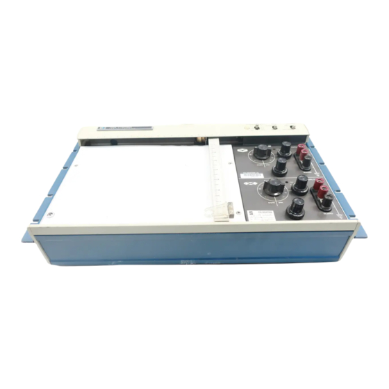
FIGURE 1-1. MODEL 7035B X-Y RECORDER FIGURE 1-2. MODEL 7035B X-Y RECORDER - OPTION 001 (WITH WING BRACKETS) -
Page 7: Instrument Identification
(HP Service Center potentiometrically, are standard features. Arbitrary full scale installation only.) voltage ranges may be used with calibrated de ranges by using a variable input attenuator. The Autogrip holddown platen 1-11. -
Page 8: Model 7035B Specifications
TABLE 1-1. MODEL 7035B SPECIFICATIONS PERFORMANCE Range Input Range: 1, 10, 100 mV/in.; 1 and 10 V/in. (Option 001, Standard Metric DC (CMR) AC (CMR) Metric calibration: 0.4, mV/cm 4 V/cm). Continuous vernier between ranges. 1 mV/in. 0.4 mV/cm 130 dB 100 dB 10 mV/in. -
Page 9: Dimension Drawing
FIGURE 1-4. DIMENSION DRAWING FIGURE 1-5. ACCESSORIES... -
Page 10: Accessory Supplies
5 feet, 10002B is 10 feet, 10002C is 5 feet with a black amplifier permits semilogplotting operations with HP X-Y and identification boot, and the 10002C is 10 feet with a black strip-chart recorders, and will operate with most other identification boot. -
Page 11: Input Resistance Characteristics
FIGURE 1-6. INPUT RESISTANCE CHARACTERISTICS saturate the amplifier's output stage causing an increased 1-34. DYNAMIC RESPONSE dead zone and decreased pen speed. Pen oscillation may also result if the noise "beats" with the servo system's carrier 1-35. Figure 1-8 indicates the typical frequency response for a frequency. -
Page 12: Typical Frequency Response (Input Filter)
FIGURE 1-7. TYPICAL FREQUENCY RESPONSE (INPUT FILTER) FIGURE 1-8. TYPICAL DYNAMIC RESPONSE... - Page 13 SECTION II INSPECTION AND INSTALLATION 2-1. INTRODUCTION 2-12. SHIPPING 2-2. This section provides information incoming 2-13. The following precautions should be taken when inspection, installation, storage, and shipping. repackaging the recorder: 2-3. INCOMING INSPECTION a. Remove disposable inkpen. Tape a piece of heavy recording paper to Autogrip table surface.
-
Page 14: Wing Bracket Installation
FIGURE 2-1. WING BRACKET INSTALLATION FIGURE 2-2. STACKED CONFIGURATION... - Page 15 SECTION III OPERATING INSTRUCTIONS 3-1. OPERATING REQUIREMENTS CAUTION Do not directly apply signals in excess of 250 volts on the X-axis or 175 volts on the 3-2. GENERAL Y-axis. 3-3. The basic function of the Model 7035B Recorder is to 3-11.
-
Page 16: Front Panel Controls
FIGURE 3-1. FRONT PANEL CONTROLS (7035B AND 7035B-001 MODELS) -
Page 17: Rear Panel
FIGURE 3-2. REAR PANEL 3-19. OPERATING PRECAUTIONS 3-27. Set the power voltage selector switch located on rear of instrument to either 115 or 230 volts, depending on the 3-20. The POWER/SERVO toggle switch apples 115 volts AC available power source. Connect power cord between the to the recorder. -
Page 18: Disposable Pen Installation
3-32. INSTALL PAPER 3-33. Install a sheet of graph paper on the recording platen, aligning lower and left edges with corresponding paper guides. Set the CHART switch to HOLD, thereby activating the AUTOGRIP holddown system. Smooth paper as necessary. 3-34. INSTALL PEN 3-35. - Page 19 SECTION IV THEORY OF OPERATION 4-1. GENERAL OPERATION DESCRIPTION the capabilities of the instrument, this rebalancing action is continuous, and the rebalance potentiometers and the pens 4-2. GUARDED INPUTS. The Model 7035B is equipped are always in a position directly proportional to the amplitude of with guarded inputs to enable high common mode rejection of the signals at the respective input terminals.
-
Page 20: Block Diagram
FIGURE 4-1. BLOCK DIAGRAM FIGURE 4-2. DETAILED BLOCK DIAGRAM... -
Page 21: Range Selector
4-13. SLIDEWIRE CIRCUIT (See Figure 4-6.) The Slidewire Circuit provides the electrical feedback to the Photochopper and Balance Circuit from the pen carriage or carriage arm. Resistors R-126 and R-125 are calibration resistors for the feedback element (slidewire) R-124. Capacitor C-108 passes unwanted spurious wiper noise to circuit common. -
Page 22: Photochopper And Balance Circuit
whenever a change in output occurs, thus increasing the rate 4-16. DIFFERENTIAL AMPLIFIER (See Figure 4-8). The ac of appearance of the balance voltage. This phase advance in error signal from the Modulator and Balance Network is applied the slowly varying error signal causes an "anticipatory" to the Gates of Q-101 and Q-102 through coupling capacitors approach to the balance point, producing damping. -
Page 23: Voltage Amplifier
is used to pull sufficient quiescent current through Zener diode the line voltage appearing in the secondary of power CR-104, thereby holding its dynamic impedance at a transformer T-601. The polarity of Point B is determined by the reasonable magnitude. Additional amplification is provided by error voltage amplifier output and will be either in phase or 180 Q-106 which is capacitor coupled from Q-105 by C-121. -
Page 24: Power And Reference Supply
combination is floated free of ground at the power transformer, 4-23. AUTOGRIP POWER SUPPLY (See Figure 4-14.) The the reference supply serves several purposes: it not only Autogrip power supply is also located on the amplifier printed furnishes the stable voltage for the balance circuit, but also circuit board. - Page 25 SECTION V MAINTENANCE, PERFORMANCE CHECKS, AND ADJUSTMENTS 5-1. INTRODUCTION b. In accessible areas and where there is only dust accumulation, cleaning can be accomplished with an air gun. 5-2. This section provides information for maintenance, In more accessible areas and where the air gun will not performance testing, functional checks, and adjustments of the remove dirt, dust, or ink, accumulations should be removed 7035B X-Y Recorder.
-
Page 26: Potentiometer Cleaning
FIGURE 5-2. POTENTIOMETER LUBRICATION potentiometer assembly (see Figure 5-2). a. Apply a thin film of lubricant on the X and Y gear drives (including idler gear). Recommended grease is Aeroshell MIL-G-7118A and 3276A or HP Part Number 6040- 0222. CAUTION Lubricant must... -
Page 27: Tilting Out Entire Circuit Board Assembly
first, such as panels, covers, etc. To disassemble/assemble, perform the following steps: NOTE Before proceeding with disassemble/assemble procedure, remove disposable pen and ac power cord. a. Bottom Cover - Stand recorder on side. Remove 8 No. 6-32 machine screws. Input attenuators, amplifiers, balance circuit, and power supply are accessible. -
Page 28: Pen Scale Removal
FIGURE 5-5. PEN SCALE REMOVAL FIGURE 5-7. REMOVAL OF X-AXIS REBALANCE POTENTIOMETER FIGURE 5-6. CARRIAGE ARM REMOVAL FIGURE 5-8. X-AXIS WIPER PROTECTION 5-23. POTENTIOMETER REPLACEMENT - X-AXIS e. Install new slidewire assembly, Part No. 07035- 5-24. The mandrel and its mounting channel are an integral 80730. -
Page 29: Servo Motor Maintenance And Backlash Adjustments
a. Remove rear hood and platen. See paragraph 5-18. 5-33. X-AXIS SERVO MOTOR REPLACEMENT b. Snap pen lift solenoid out of its spring holder and 5-34. To remove: remove holder and X-axis pointer by removing 1 mounting screw. a. Remove rear hood and platen. See paragraph 5-18. c. -
Page 30: Nylon Cable (Attachment To Pen Block)
d. From bottom of recorder, unsolder 2 wires, noting NOTE: If either servo motor was removed, install per their polarity. Remove 1 capacitor. paragraph 5-34 or 5-36. e. Remove 2 screws and clamps mounting motor. 5-39. CORRECTION OF STICKING MOTOR BRUSHES Withdraw motor from block. -
Page 31: Restringing Diagram
FIGURE 5-11. RESTRINGING DIAGRAM d. Attach loop to center of cable yoke (Point A). Route i. Clip off the excess wire. cable around right-hand side of cable yoke (Point B), and pass it in front of cable yoke to pulley C. Continue around pulley C 5-45. -
Page 32: Recommended Test Equipment
Y-axis. 2. HP MODEL 3310A FUNCTION GENERATOR c. Apply 1 volt to X input terminals. 3. HP MODEL 410C or 427A DC VOLTMETER d. Pen should stop at 10 inches (25 cm) within ±0.020 in. (0.5 mm). HP MODEL 202A LOW FREQUENCY FUNCTION GENERATOR e. -
Page 33: Slewing Speed Determination
a. Set RANGE switch to 1 mV/in. (0.4 mV/cm). Connect input terminals with short between high (+) and guard, and 1K Resistor between low (-) and guard. b. Connect DC Standard between Y guard terminal and ground. c. Set DC Standard to 500 volts. d. -
Page 34: Y Gear Train Backlash Adjustment
FIGURE 5-15. Y-AXIS DRIVE STRING FIGURE 5-16. Y-AXIS BACKLASH ADJUSTMENT (GEAR TENSION CHECK ADJUSTING SCREW) 5-68. Y GEAR TRAIN BACKLASH ADJUSTMENT 5-69. The Y-axis drive system alignment requires adjusting two gears. These two gears must be adjusted for backlash in proper sequence for best results. -
Page 35: Y-Axis Alignment
5-74. X-AXIS CABLE TENSION CHECK/ADJUSTMENT 5-75. The X cable tension should be verified by measuring the force required to displace it at a given distance. With the arm at the extreme right, the force required to displace (in a plane parallel to the control panel and in a direction toward the front of the unit) the center of the longest span of the cable 1/4 inch past the vertical wall of the motor assembly trough shall be... -
Page 36: Y-Axis Alignment
FIGURE 5-19. Y-AXIS ALIGNMENT FIGURE 5-20. X-AXIS CABLE TENSION CHECK FIGURE 5-21. X-AXIS DRIVE BELT TENSION CHECK 5-12... -
Page 37: Gear Train Backlash Adjustment
CAUTION Do not overtighten this adjustment. This could result in bearing damage or failure. 5-86. X-AXIS DRIVE TRAIN BEARING REPLACEMENT 5-87. To replace any of the X-axis drive bearings, the X-axis drive cable must be partially or completely removed, depending on which bearing is affected. See Figure 5-23. 5-88. -
Page 38: Electrical Adjustments
FIGURE 5-23. X-AXIS GEAR TRAIN BEARINGS c. Remove two clamps holding pulley housing. Slip c. Turn on recorder. drive belt off pulley and pull assembly (A) out of its hold from bottom. See Figure 5-23. d. Adjust R237 until minimum retrace error exists. d. -
Page 39: Phase Shift Adjustment
f. Remove signal from X input terminals. g. Apply 0.7 Vdc (0.9 Vdc) to Y input terminals. h. Adjust R126 to position pen to full scale. i. In the event full scale cannot be reached by using calibration controls, check electronic reference for output of 9.0 volts ±5%. -
Page 40: Parts List
SECTION VI PARTS LIST 6-1. INTRODUCTION 6-10. CODE LIST OF MANUFACTURERS 6-2. This section contains complete information on parts list 6-11. Table 6-4 lists the five-digit code number assigned to a presented in an alphanumerical and numerical order. specific manufacturer. This table is a cross-reference to Table procedure for ordering replacement parts is also contained in 6-1 in that the five-digit number listed in Table 6-1 is identified this section. -
Page 41: Parts List
TABLE 6-1. PARTS LIST Reference HP Part Number Description Mfr Part Number Designation Code X-Y RECORDER B101 5080-3696 Y-AXIS SERVO MOTOR 28480 5080-3696 B201 5080-3695 X-AXIS SERVO MOTOR 28480 5080-3695 C101 0160-0819 C:FXD MY 0 047 UF 10% 600VDCW 14655... - Page 42 TABLE 6-1. PARTS LIST (Continued) Reference HP Part Number Description Mfr Part Number Designation Code CR501 1901-0470 DIODE:SILICON 0.75A 1000PIV 28480 1901-0470 CR502 1901-0470 DIODE:SILICON 0.75A 1000PIV 28480 1901-0470 CR503 1901-0470 DIODE:SILICON 0.75A 1000PIV 28480 1901-0470 CR504 1901-0470 DIODE:SILICON 0.75A 1000PIV...
- Page 43 TABLE 6-1. PARTS LIST (Continued) Reference HP Part Number Description Mfr Part Number Designation Code R111 0698-4342 R:FXD FLM 90K OHM 0.1% 1/8W 28480 0698-4342 R112 0757-0201 R:FXD FLM 6.81K OHM 1% 1/8W 28480 0757-0201 R113 0757-0433 R:FXD MET FLM 3.32K OHM 1% 1/8W...
- Page 44 TABLE 6-1. PARTS LIST (Continued) Reference HP Part Number Description Mfr Part Number Designation Code R222 0684-1041 R:FXD COMP 100K OHM 10% 1/4W 01121 CB 1041 R223 2100-2682 R:VAR WW 10K OHM 10% LIN 2W 28480 2100-2682 R224 07035-80730 SLIDEWIRE ASSY:5K OHM...
-
Page 45: Miscellaneous Parts
TABLE 6-2. MISCELLANEOUS PARTS Circuit Mfr Part Part No. Description Typical Mfr Symbol MECHANICAL, ELECTRICAL, ETC. 1251-0293 Connector, 24-pin (mate for J-602) Amphenol 57-30240 1400-0084 Fuse holder Littlefuse 342004 17999-06494 Pulley, Drive cable (white plastic) 17999-06494 17999-06460 Spring, Cable tension 17999-06460 17999-16046 Clamp and Pad Assy (for shipping) -
Page 46: Recommended One Year Isolated Spare Parts List
TABLE 6-3. RECOMMENDED ONE YEAR ISOLATED SPARE PARTS LIST Circuit Symbol Part No. Description Typical Mfr Mfr Part No. B-101 5080-3696 Servo Motor, Y-axis 5080-3696 B-201 5080-3695 Servo Motor, X-axis 5080-3695 C-402 0180-1984 Sprague 34D357G050 Cap, Elect, 350µf, +75 -10% 50wvdc CR-104 1902-0034 Diode, Zener, 5.76v, ±10%... -
Page 47: Manufacturer's Code List
TABLE 6-3. RECOMMENDED ONE YEAR ISOLATED SPARE PARTS LIST (Continued) Circuit Symbol Part No. Description Typical Mfr Mfr Part No. R-124 07035- Resistor, Variable, 3.5K (Slidewire) 07035-80750 80750 5080-7706 Wiper Assembly, (Y-axis) R-224 07035- Resistor, Variable, 5K (Slidewire) 07035-80730 80730 5060-4570 Wiper Assembly, (X-axis) For serial prefixes below 823, coil and wiper... - Page 48 TM 11-6625-2850-14&P FIGURE 6-1. EXPLODED VIEW-CABINET...
- Page 49 TM 11-6625-2850-14&P FIGURE 6-2. EXPLODED VIEW-CARRIAGE ARM (SHEET 1 OF 2) 6-10...
- Page 50 Part No. Description Typical Mfr. 0360-0243 Solder Lug, Flat #2 Zierick Mfg. Co. 1460-0940 Spring, Retaining Superior Spring 0520-0066 Screw, Machine, 2-56 x 3/16 PH, PD, SS Schnitzer Alloy 0520-0163 Screw, Machine, 2-56 x 3/16 FH, PD, SS Hewlett-Packard 2200-0710 Screw, Machine, 4/40 x 3/8 Truss, Set, Pass, Slot 0570-0142 Screw, Set 2-56 x 1/8 Spline Dr.
-
Page 51: Troubleshooting
SECTION VII TROUBLESHOOTING 7-1. INTRODUCTION determining which circuits or sections are not operating or are operating abnormally. This is generally the fastest method to 7-2. CONTENT locate trouble in a closed loop circuit. When troubleshooting utilize the photographs and schematics presented in this 7-3. -
Page 52: 7035B Troubleshooting Index
TABLE 7-1. 7035B TROUBLESHOOTING INDEX PROBLEM POSSIBLE CAUSE CURE One position of pen produces "Dirty" slidewire. High contact Clean slidewire (see paragraph 5-11). excessive jitter that repeats resistance between slidewire each time the pen reaches wiper and either resistance ele- this position. - Page 53 TABLE 7-1. 7035B TROUBLESHOOTING INDEX (Continued) PROBLEM POSSIBLE CAUSE CURE (cont) X-axis slider rod bearings too Adjust slide rod bearings tight. (paragraph 5-85). Insufficient backlash in gears Adjust backlash (paragraph 5-83). (too tight). Motor brushes excessively worn. Replace brushes (paragraph 5-38). Pen speed too fast.
- Page 54 TABLE 7-1. 7035B TROUBLESHOOTING INDEX (Continued) PROBLEM POSSIBLE CAUSE CURE (cont) Excessive X-axis gear backlash. Adjust backlash (paragraph 5-83). X-axis motor stalls when X drive belt too tight. Measure Adjust (loosen) drive belt end of scale stops are per paragraph 5-78. (paragraph 5-79).
- Page 55 TABLE 7-1. 7035B TROUBLESHOOTING INDEX (Continued) PROBLEM POSSIBLE CAUSE CURE Y-axis acceleration too Drive string too loose. Measure Tighten drive string slow. tension per paragraph 5-66. (see paragraph 5-67). Input signal source impedance too high Lower source impedance and/or (1 mv/inch, 0.4 mv/cm) range only. increase amplifier gain (see paragraph 5-92).
- Page 56 TABLE 7-1. 7035B TROUBLESHOOTING INDEX (Continued) PROBLEM POSSIBLE CAUSE CURE (cont) Amplifier gain too low. Adjust amplifier gain (see paragraph 5-92). Damping capacitor improper Replace capacitor. Increasing value. value decreases overshoot. Excessive X-axis over- Drive belt too loose. Measure Tighten drive belt shoot.
- Page 57 TABLE 7-1. 7035B TROUBLESHOOTING INDEX (Continued) PROBLEM POSSIBLE CAUSE CURE (cont) Bearing in drive train faulty. Replace bearing (paragraph 5-87). Motor brushes excessively Replace brushes (see worn. paragraph 5-38). Motor brush stuck, held off See paragraph 5-39. commutator. Excessive friction. Clean and lubricate per paragraphs 5-9 and 5-12.
-
Page 58: Component Identification
FIGURE 7-1. COMPONENT IDENTIFICATION-FRAME... - Page 59 TM 11-6625-2850-14&P Figure 7-2. Component Identification - Circuit Board.
-
Page 60: Schematic Model 7035B (D-07035-92550)
TM 11-6625-2850-14&P Figure 7-3. Schematic Model 7035B (D-07035-92550). 7-10... -
Page 61: Backdating
SECTION VIII BACKDATING 8-1. REQUIREMENTS Page 2-2, Figure 2-1, change Rack Mount Brackets part no. to 07035-00490. 8-2. DEFINITIONS Page 6-3, Table 6-1, change J-601 part no. to 8120-3148. 8-3. This section provides information on serial prefixes below 845. Table 8-1 is a tabular presentation of the serial Page 6-6, Table 6-2, Spare Parts, change the following items: prefix numbers and the corresponding change numbers. -
Page 62: Component Identification - Circuit Board
TM 11-6625-2850-14&P FIGURE 8-1. COMPONENT IDENTIFICATION - CIRCUIT BOARD... -
Page 63: Change Ii
8-6. CHANGE II 8-7. IEC. Page. All photos and illustrations of Front Panel will appear as shown: FIGURE 8-2. CONTROL PANELS - MODEL 7035B AND 7035B-001 Delete IEC from Rear Connector. 8-8. CHANGE III 8-9. IEC. Page 6-3, Table 6-1, change DS601 and F601 to read: DS601 1450-0123 Indicator Light... -
Page 64: Change Iv
Page 6-7, Table 6-3, change DS 601 and F601 to read: DS601 1450-0123 Indicator Light 08717 859-R-6 Sloan F601 2110-0063 Fuse, 0.75A, 2A 250V 75915 312.750 Littlefuse 1400-0085 Holder -Fuse 75915 342004 Littlefuse Page 7-9, Figure 7-3, make the following change to the schematic: FIGURE 8-3. - Page 65 Page 4-1, add new paragraphs 4-6A and 4-6B to read: ink stops flowing. Pen assemblies should be cleaned thoroughly every two to four weeks. Clean by soaking 4-6A. PEN SYSTEM in alcohol or hot water. Clogging during operation may be cleared by one or more of the following steps: 4-6B.
-
Page 66: Exploded View - Carriage Arm
TM 11-6625-2850-14&P FIGURE 8-5. EXPLODED VIEW - CARRIAGE ARM... - Page 67 Page 6-9, Figure 6-1, change PEN SCALE part no.'s to: BLANK 07035-60185 ENGLISH 07035-60186 METRIC 07035-60250 Page 7-7, Table 7-1, new item 33 to read: 33. Pen won't write a. Pen tip clogged. a. See paragraph 5-18B. b. Pen reservoir empty. b.