Hitachi DH 30PC2 Technical Data And Service Manual
Hide thumbs
Also See for DH 30PC2:
- Handling instructions manual (112 pages) ,
- Safety instructions and instruction manual (68 pages) ,
- Handing instructions (26 pages)

Related Manuals for Hitachi DH 30PC2


Summary of Contents for Hitachi DH 30PC2
- Page 1 MODEL DH 30PC2 Hitachi Power Tools TECHNICAL DATA ROTARY HAMMER DH 30PC2 SERVICE MANUAL LIST No. E494 Aug. 2006 SPECIFICATIONS AND PARTS ARE SUBJECT TO CHANGE FOR IMPROVEMENT...
- Page 2 REMARK: Throughout this TECHNICAL DATA AND SERVICE MANUAL, a symbol(s) is(are) used in the place of company name(s) and model name(s) of our competitor(s). The symbol(s) utilized here is(are) as follows: Competitor Symbol Utilized Company Name Model Name GBH4DFE BOSCH HR3000C MAKITA...
-
Page 3: Table Of Contents
8. REFERENCE INFORMATION ..................... 13 8-1. Grease Replacement ......................13 8-2. O-ring Replacement ......................13 8-3. Structure of the Model DH 30PC2 Rotary Hammer ............13 8-4. "Three-Mode" Changeover Mechanism ................16 8-5. Caution when Using "Rotation Only" (No Hammering) Function ........18 8-6. -
Page 4: Product Name
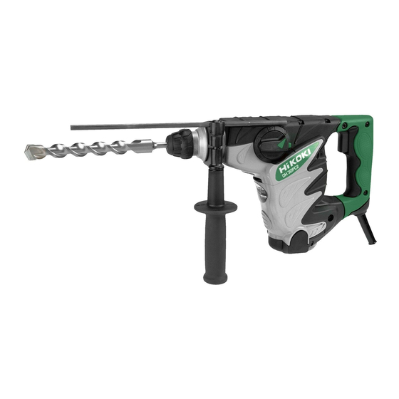
2. MARKETING OBJECTIVE The new Model DH 30PC2 features the concrete drilling capacity with the maximum drill bit diameter 30 mm and the use of SDS-plus shank tools. It can provide 3 modes of operation, "Rotation and hammering," "Rotation only"... -
Page 5: Selling Points
4-1-1. Highest drilling speed and chipping performance in the class The drilling speed of the Model DH 30PC2 is 1.3 times higher than C and equivalent to or higher than B thanks to the efficient transmission of the hammering energy. - Page 6 4-1-5. Variable locking mechanism The Model DH 30PC2 is equipped with a variable locking mechanism that allows the angle of a tool such as a cold chisel or a cutter to be rotated conveniently to 36 individual positions in relation to the work in the "Hammering only"...
-
Page 7: Specifications
5. SPECIFICATIONS 5-1. Specifications Model DH 30PC2 Capacity 4 -- - 30 mm (5/32" -- - 1-3/16") Concrete 13 mm (1/2") Steel Wood 32 mm (1-1/4") 90 mm (3-17/32") Core bit Power source AC single phase 50 Hz or 60 Hz... -
Page 8: Optional Accessories
5-2. Optional Accessories A. Drilling anchor holes (rotation + hammering) Drill bit (taper shank) (2) Taper shank adapter (3) Cotter (1) Drill bit (taper shank) (SDS-plus shank) (1) Drill bit (Taper shank) (2) Taper shank adapter (3) Cotter Type Code No. Code No. - Page 9 C. Large hole boring (rotation + hammering) Center pin, core bit, core bit shank and guide plate Core bit shank Center pin Core bit (Guide plate) (SDS-plus shank) (1) Center pin (Do not use bit with outer diameter of 25 mm (1") and 29 mm (1-1/8") Center pin (A) Core bit (outer diameter) 32, 35, 38 mm (1-1/4", 1-3/8", 1-1/2") Code No.
- Page 10 E. Crushing operations (hammering only) Bull point (round type) Square bull point (SDS-plus shank) (SDS-plus shank) Code No. 303046 Code No. 316656 F. Groove digging and edging (hammering only) Cold chisel Cutter (SDS-plus shank) (SDS-plus shank) Code No. 316657 Code No. 316658 G.
- Page 11 (1) Cross-recessed head (Phillips) bit (2) Slotted-head (minus) bit [Overall length: 70 mm] [Overall length: 50 mm] (For use with cross-recessed head (Phillips) screw) (For use with slotted-head (minus) screw) Stamped bit No. Tip thickness Bit No. Code No. Bit tip thickness Code No. Applicable screw dia.
- Page 12 K. Grease for electric impact drill Containing 500 g (17.64 oz): Code No. 980927 Containing 30 g (1.06 oz.): Code No. 981840 70 g (2.5 oz.): Code No. 308471 L. Dust cup Dust cup Code No. 971787 --- 9 ---...
-
Page 13: Comparisons With Similar Products
6. COMPARISONS WITH SIMILAR PRODUCTS 6-1. Specification Comparison Maker HITACHI HITACHI DH 30PC2 DH 30PC Model Concrete 30 (1-3/16") 30 (1-3/16") 30 (1-3/16") 30 (1-3/16") 13 (1/2") 13 (1/2") Steel 13 (1/2") 13 (1/2") Capacity Wood 32 (1-1/4") 32 (1-1/4") 32 (1-1/4") -
Page 14: Drilling Speed Comparison
6-2. Drilling Speed Comparison Drilling speed varies considerably depending on the work conditions. Use the factory test results shown in Fig. 1 for comparison purpose only. HITACHI DH 30PC2 HITACHI DH 30PC Drill bit dia. (mm) Fig. 1 [Test conditions]... -
Page 15: Precautions In Sales Promotion
7. PRECAUTIONS IN SALES PROMOTION In the interest of promoting the safest and most efficient use of the Model DH 30PC2 Rotary Hammer by all of our customers, it is very important that at the time of sale the salesperson carefully ensures that the buyer seriously recognizes the importance of the contents of the Handling Instructions, and fully understands the meaning of the precautions listed on the Caution Plate attached to each tool. -
Page 16: Reference Information
8-1. Grease Replacement The striking portion and the speed reduction portion of the Model DH 30PC2 respectively use different types of grease. It is not necessary to replenish the grease unless the tool is disassembled for repair or there is grease leakage due to a damaged seal. - Page 17 Connecting rod Second Striker Clutch Front cap hammer Piston Crank shaft Bevel Grip Cylinder chamber gear First gear Key rail Retainer O-ring sleeve Steel ball Needle pin Second gear Bevel pinion Armature Fig. 3 Mechanism to prevent idle hammering When the working tool is released from the workpiece, slide sleeve (A) and the second hammer are forcibly moved to the position illustrated in Fig.
- Page 18 A clutch plate holding a steel ball is inserted between the second gear and the spring as a slip mechanism in the Model DH 30PC2. If an excessively large torque is applied to the tool shaft, the second gear idles and does not transmit rotation.
-
Page 19: Three-Mode" Changeover Mechanism
8-4. "Three-Mode" Changeover Mechanism The change lever of the Model DH 30PC2 permits quick and easy changeover among the "Rotation and hammering", "Rotation only" and "Hammering only" functions. Each function mode is explained below. When operating the change lever, be sure to continue pressing the pushing button. - Page 20 Air hole Cylinder Lock sleeve Clutch Slide sleeve (A) Bevel gear Change lever Fig. 7 Rotation only (Fig. 8) Adjust the change lever to "Rotation only" ( mark). Claws of the bevel gear engage with matching claws of the clutch and rotation is transmitted to the cylinder coupled to the clutch. Thus the tool is turned. When the lock sleeve is moved toward the tip, the amount of backward movement of slide sleeve (A) is limited to the position where it contacts the lock sleeve to keep the air hole of the cylinder opened.
-
Page 21: Caution When Using "Rotation Only"(No Hammering) Function
Neutral (Fig. 9) The Model DH 30PC2 has a neutral mode used for positioning a tool such as a cold chisel. Adjust the change lever to "Neutral" ( mark). Engagement between the bevel gear and the clutch is released and no rotation is transmitted. -
Page 22: Drill Bits
8-6. Drill Bits The chuck section is designed exclusively for the popular and widely available SDS-plus shank bits as shown in Fig. 10. Rotating torque is transmitted to the drill bit by two key rails provided in the tool holding section. A steel ball is used to prevent the bit from coming off. -
Page 23: Tool Retainer
8-7. Tool Retainer The tool retainer is structured as shown in Fig. 12. The tip of the tool retainer is covered with the front cap (made of rubber) to prevent dust and chips from getting inside. The steel ball falls into the round groove of the bit to prevent the tool from coming off and the two key rails transmit the rotation torque. -
Page 24: Precautions In Disassembly And Reassembly
9. PRECAUTIONS IN DISASSEMBLY AND REASSEMBLY The numbers in [Bold] correspond to the item numbers in the Parts List and exploded assembly diagrams. 9-1. Disassembly (1) Disassembly of the retainer As shown in Fig. 13, pull the Grip [2] fully in the arrow direction and remove the Front Cap [1]. (Pull the Front Cap [1] strongly because it is made of rubber and fitted to the grip securely.) Then, the Grip [2] can also be removed. - Page 25 Retainer Sleeve [18] Cylinder Case [9] Clutch Spring [35] Retaining Ring [7] Lock Sleeve [39] Clutch [40] Lock Spring [38] Sleeve [16] Fig. 15 Sleeve (C) [20] Slide Sleeve (B) [33] Striker [31] Cylinder [36] Retainer Sleeve [18] Slide Ring [30] Second Hammer [23] Needle Pin [19] Retaining Ring D38 [21]...
- Page 26 Slide Ring [30] Cylinder [36] Slide Sleeve (A) [34] Slide Sleeve (B) [33] Fig. 17 (4) Removal of the Piston [44] The Piston [44] is remainded in the Crank Case [94]. Move the Crank Shaft [92] to the bottom dead center then the piston ass'y can be removed from the Crank Shaft [92].
- Page 27 Hand press First Gear [98] Crank Case [94] Crank Shaft [92] Support Fig. 20 --- 24 ---...
-
Page 28: Reassembly
9-2. Reassembly Reassembly can be accomplished by following the disassembly procedures in reverse. However, special attention should be given to the following items. (1) Mouting the First Gear [98] and the Crank Shaft [92] Press-fit Oil Seal (B) [75] in the Crank Case [94] then the O-ring (S-32) [96] is fitted in the groove inside the Crank Case [94]. - Page 29 (3) Mounting components in the Cylinder [36] Fit Slide Sleeve (A) [34] and Slide Sleeve (B) [33] on the outer circumfenrence of the Cylinder [36] and move Slide Sleeve (A) [34] and Slide Sleeve (B) [33] until they contact the outside flange of the Cylinder [36]. At this time, align the slotted hole of the Cylinder [36] with the groove of Slide Sleeve (B) [33].
- Page 30 Slide Sleeve (B) [33] Retainer Sleeve [18] Sleeve (C) [20] Slide Ring [30] Cylinder [36] Retaining Ring D38 [21] Second Hammer [23] Slide Sleeve (A) [34] Fig. 26 Crank Case [94] Connecting Rod [45] Crank Shaft [92] Fig. 27 (4) Mounting the Fan Guide [70] Mount the Fan Guide [70] to the Housing Ass'y [106] being careful of the concave porrtion of the Fan Guide [70].
-
Page 31: Screw Locking Agent Tb1401
(5) Lubrication Apply Hitachi Motor Grease No. 29 to the following places: Apply 30 g (1 oz) to the gears in the Gear Cover [100] and the Crank Case [94], and coat grease on the Needle Bearing (M661) [99] (motor ass'y), Steel Ball D7.0 [17], pinion of armature ass'y. -
Page 32: Tightening Torque
9-4. Tightening Torque + 20 + 1.96 Cylinder case mounting bolt ............9.8 m (100 • • (Seal Lock Hex. Socket Hd. Bolt M6 x 22 [8]) + 20 + 1.96 Crank case mounting bolt ............9.8 m (100 • •... -
Page 33: Wiring Of Variable Speed Control Switch
9-6. Wiring of Variable Speed Control Switch Insert each cord into the terminal 1 and terminal 2 of the speed control switch as shown in Fig. 31 and tighten the screw [tightening torque: 0.6 0.2 N m (6 2 kg cm, 5.2 1.7 in-lbs.)]. -
Page 34: Standard Repair Time (Unit) Schedules
10. STANDARD REPAIR TIME (UNIT) SCHEDULES Variable 60 min. MODEL Fixed Work Flow DH 30PC2 Housing Ass'y Stator Ass'y Switch Cord Gear Cover Cord Armor Needle Bearing Tail Cover Armature Ass'y Ball Bearing (6001DD) Crank Case Ball Bearing Cover (608VV) - Page 35 Hitachi Power Tools LIST NO. E494 ELECTRIC TOOL PARTS LIST ROTARY HAMMER 2006 • • Model DH 30PC2 (E1)
- Page 36 PARTS DH 30PC2 ITEM CODE NO. DESCRIPTION REMARKS USED 323-078 FRONT CAP 323-077 GRIP 306-340 STOPPER RING 323-076 BALL HOLDER 323-075 RETAINER SPRING 325-668 WASHER (D) 306-993 RETAINING RING 321-313 SEAL LOCK HEX. SOCKET HD. BOLT M6X22 325-651 CYLINDER CASE...
- Page 37 PARTS DH 30PC2 ITEM CODE NO. REMARKS DESCRIPTION USED 986-940 SEAL LOCK HEX. SOCKET HD. BOLT M6X45 321-867 LEVER LABEL 983-162 SEAL LOCK HEX. SOCKET HD. BOLT M4X12 321-309 CHANGE LEVER 321-312 PIN D2X10 325-671 LEVER HOLDER 948-391 RETAINING RING FOR D40 HOLE...
- Page 38 PARTS DH 30PC2 ITEM CODE NO. DESCRIPTION REMARKS USED 872-767 O-RING (S-32) 948-001 RETAINING RING FOR D32 HOLE 325-645 FIRST GEAR 939-299 NEEDLE BEARING (M661) 325-674 GEAR COVER 325-680 HANDLE (A).(B) SET 994-192 HEX. SOCKET HD. BOLT (W/FLANGE) M5X16 302-089...
-
Page 39: Standard Accessories
STANDARD ACCESSORIES DH 30PC2 ITEM CODE NO. DESCRIPTION REMARKS USED 325-679 CASE 971-787 DUST CUP 318-085 SYRINGE (BELLOWS TYPE) OPTIONAL ACCESSORIES ITEM CODE NO. DESCRIPTION REMARKS USED 303-046 BULL POINT (SDS+) 250MM (ROUND SHANK TYPE) 303-044 CHEMICAL ANCHOR ADAPTER (SDS+) 12.7MMX90L 303-045 CHEMICAL ANCHOR ADAPTER (SDS+) 19.0MMX100L... - Page 40 OPTIONAL ACCESSORIES DH 30PC2 ITEM CODE NO. DESCRIPTION REMARKS USED 982-687 GUIDE PLATE (FOR CORE BIT 35MM) 982-676 CORE BIT (A) 38MM INCLUD. 644 982-688 GUIDE PLATE (FOR CORE BIT 38MM) 982-677 CORE BIT (B) 45MM INCLUD. 646 982-689 GUIDE PLATE (FOR CORE BIT 45MM)
- Page 41 OPTIONAL ACCESSORIES DH 30PC2 ITEM CODE NO. REMARKS DESCRIPTION USED 303-616 DRILL BIT (SDS PLUS) D25.0X450 319-988 DRILL BIT (SDS PLUS) D30.0X450 8 -- 06 * ALTERNATIVE PARTS --- 7 -- -...
- Page 42 DH 30PC2 ITEM CODE NO. DESCRIPTION REMARKS USED --- 8 --- Printed in Japan 8 -- 06 (060803N)