Sony SLV-D350P Service Manual
Dvd player/video cassete recorder
Hide thumbs
Also See for SLV-D350P:
- Service manual (121 pages) ,
- Specifications (2 pages) ,
- Operating instructions manual (129 pages)
Table of Contents
Advertisement
Quick Links
QQ
3 7 63 1515 0
SERVICE MANUAL
TE
L 13942296513
System
Laser
Semiconductor laser
Format
VHS NTSC standard
Video recording system
Rotary head helical scanning FM system
Video heads
Double azimuth four heads
Video signal
NTSC color, EIA standards
Tape speed
3
SP: 33.35 mm/s (1
inches/s)
8
EP: 11.12 mm/s (
7
inches/s)
16
11
LP: 16.67 mm/s (
inches/s),
16
playback only
Maximum recording/playback time
8 hrs. in EP mode (with T-160 tape)
Rewind time
Approx. 1 min (with T-120 tape)
www
.
http://www.xiaoyu163.com
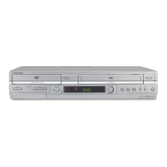
SLV-D350P/D550P
Photo: SLV-D550P
RMT-V501D
Tuner section
Channel coverage
VHF 2 to 13
UHF 14 to 69
CATV A-8 to A-1, A to W, W+1 to W+84
Antenna
75-ohm antenna terminal for VHF/UHF
Inputs and outputs
LINE IN 1 and LINE-2 IN
VIDEO IN, phono jack (1 each)
Input signal: 1 Vp-p, 75 ohms, unbalanced, sync
negative
AUDIO IN, phono jacks (2 each)
Input level: 327 mVrms
Input impedance: more than 47 kilohms
LINE OUT
VIDEO OUT, phono jack (1)
Output signal: 1 Vp-p, 75 ohms, unbalanced, sync
negative
AUDIO OUT, phono jacks (2)
Standard output: 327 mVrms
Load impedance: 47 kilohms
Output impedance: less than 10 kilohms
x
ao
u163
y
i
http://www.xiaoyu163.com
2 9
8
Refer to the SERVICE MANUAL of VHS MECHANI-
CAL ADJUSTMENT MANUAL VII for MECHANICAL
ADJUSTMENTS. (9-921-790-11)
Q Q
3
6 7
1 3
1 5
SPECIFICATIONS
DIGITAL OUT
OPTICAL, Optical output jack
-18 dBm (wave length: 660 nm)
COAXIAL, phono jack
Output signal: 0.5 Vp-p, 75 ohms
COMPONENT VIDEO OUT (Y, Pb, Pr)
Phono jack
Y: 1.0 Vp-p/Pb, Pr: 0.7 Vp-p, 75 ohms
S-VIDEO OUT
4-pin, mini-DIN jack
Y: 1.0 Vp-p, unbalanced, sync negative
C: 0.286 Vp-p, load impedance 75 ohms
Timer section
Clock
Quartz locked
Timer indication
12-hour cycle
Timer setting
8 programs (max.)
General
Power requirements
120 V AC, 60 Hz
VIDEO CASSETTE RECORDER
co
.
9 4
2 8
RMT-V501C/V501D
US Model
TS-10 MECHANISM
0 5
8
2 9
9 4
2 8
Power consumption
25 W
Power back-up
Back-up duration: 0 min
Operating temperature
0°C to 45°C (32°F to 113°F)
Storage temperature
-20°C to 60°C (-4°F to 140°F)
Operating humidity
25% to 80%
Dimensions including projecting parts and controls
(w/h/d)
×
×
Approx. 430
85
287 mm
×
×
(Approx. 17
3.4
11.5 inches)
Mass
Approx. 3.6 kg (Approx. 7.9 lbs)
Supplied accessories
Remote commander (1)
Size AA (R6) batteries (2)
75-ohm coaxial cable with F-type connectors (1)
×
3 y pinplug
Audio/video cord (pinplug
Design and specifications are subject to change without
notice.
ENERGY STAR
¤
is a U.S. registered mark.
¤
As an ENERGY STAR
Partner, Sony Corporation has
determined that this product meets the ENERGY STAR
guidelines for energy efficiency.
DVD PLAYER/
m
9 9
9 9
×
3) (1)
¤
Advertisement
Table of Contents

Related Manuals for Sony SLV-D350P


Summary of Contents for Sony SLV-D350P
-
Page 1: Specifications
120 V AC, 60 Hz ENERGY STAR ¤ is a U.S. registered mark. ¤ As an ENERGY STAR Partner, Sony Corporation has determined that this product meets the ENERGY STAR ¤ guidelines for energy efficiency. DVD PLAYER/ VIDEO CASSETTE RECORDER u163 http://www.xiaoyu163.com... - Page 2 LINE WITH MARK 0 ON THE SCHEMATIC DIAGRAMS AND IN THE PARTS LIST ARE CRITICAL TO SAFE OPERATION. REPLACE THESE COMPONENTS WITH SONY PARTS WHOSE PART NUMBERS APPEAR AS SHOWN IN THIS MANUAL OR IN SUPPLEMENTS PUBLISHED BY SONY. — 2 —...
-
Page 3: Table Of Contents
http://www.xiaoyu163.com 3 7 63 1515 0 TABLE OF CONTENTS Precautions DVD Deck 2-6-1 Holder Chuck Removal ··················································· 2-22 Safety Precautions ·································································· 4 2-6-2 Tray Disc Removal ·························································· 2-23 Servicing Precautions ···························································· 6 2-6-3 Ass’y P/U Deck Removal ··············································· 2-24 ESD Precautions ····································································· 7 2-6-4 Ass’y Housing Removal ··················································... -
Page 4: Safety Precautions
http://www.xiaoyu163.com 3 7 63 1515 0 PRECAUTIONS 1 SAFETY PRECAUTIONS 1) Before returning an instrument to the customer, always make a (4) Insulation Resistance Test Cold Check-(1) Unplug the power safety check of the entire instrument, including, but not limited supply cord and connect a jumper wire between the two prongs of to, the following items: the plug. - Page 5 http://www.xiaoyu163.com 3 7 63 1515 0 6) Product Safety Notice-Some electrical and mechanical parts have special safety-related characteristics which are often not evident from visual inspection, nor can the protection they give necessarily be obtained by replacing them with components rated for higher voltage, wattage, etc.
-
Page 6: Servicing Precautions
http://www.xiaoyu163.com 3 7 63 1515 0 2 SERVICING PRECAUTIONS CAUTION: Before servicing units covered by this service manual and its supplements, read and follow the Safety Precautions section of this manual. Note: If unforseen circument create conflict between the following servicing precautions and any of the safety precautions, always follow the safety precautions. -
Page 7: Esd Precautions
http://www.xiaoyu163.com 3 7 63 1515 0 3 ESD PRECAUSIONS Electrostatically Sensitive Devices (ESD) Some semiconductor (solid state) devices can be damaged easily by static electricity. Such components commonly are called Electrostatically Sensitive Devices (ESD). Examples of typical ESD devices are integrated circuits and some field-effect transistors and semiconductor chip components. -
Page 8: Handling The Optical Pick-Up
http://www.xiaoyu163.com 3 7 63 1515 0 4 HANDLING THE OPTICAL PICK-UP The laser diode in the optical pick up may suffer electrostatic breakdown because of potential static electricity from clothing and your body. The following method is recommended. (1) Place a conductive sheet on the work bench (The black sheet used for wrapping repair parts.) (2) Place the set on the conductive sheet so that the chassis is grounded to the sheet. -
Page 9: Pick-Up Disassembly And Reassembly
http://www.xiaoyu163.com 3 7 63 1515 0 5 PICK-UP DISASSEMBLY AND REASSEMBLY 5-1 Disassembly 5-2 Assembly 1) Replace the Pick-up. 1) Remove the power cord. 2) Remove the soldering 2 points on Pick-up. 2) Disassemble the Deck-Assy. 3) Reassemble the Deck-Assy. 3) Make solder land 2 points short on Pick-up. - Page 10 http://www.xiaoyu163.com 3 7 63 1515 0 MEMO L 13942296513 u163 — 10 — http://www.xiaoyu163.com...
-
Page 11: General
• If you enter a new code number, the code number previously entered will be erased. The remote commander is preprogrammed to control non-Sony TVs. If your TV is • If the TV uses a different remote control system from the one programmed to work with the listed in the following table, set the appropriate manufacturer’s code number. - Page 12 • Be sure you make connections firmly. Loose connections may cause picture A Use this hookup if your TV has stereo jacks distortion. • If your TV does not match any of the examples provided, see your nearest Sony DVD-VCR Stereo receiver dealer or qualified technician.
- Page 13 http://www.xiaoyu163.com 3 7 63 1515 0 Hookup 2 : DVD-VCR setup Hookup 2 (Plug and Play) Plug the DVD-VCR into an AC outlet. You have no cable box, or a cable box with only a few The DVD-VCR automatically presets the DVD-VCR’s clock and TV channels scrambled channels when the DVD-VCR is plugged into the AC outlet.
- Page 14 http://www.xiaoyu163.com 3 7 63 1515 0 Press SET UP to exit the menu. Step 5 : Setting the clock Using the Auto Clock Set SET UP feature Some TV and cable channels transmit time signals with their broadcasts. Your DVD- VCR can pick up this time signal to automatically set the clock.
- Page 15 http://www.xiaoyu163.com 3 7 63 1515 0 Press V/v to select “ Manual ” , then press CLOCK SET/ADJUST Step 6 : Presetting channels ENTER. Time Date Year 12:00 1/01 2004 This DVD-VCR is capable of receiving VHF channels 2 to 13, UHF channels 14 to 69 and RETURN SET UP SET UP...
- Page 16 http://www.xiaoyu163.com 3 7 63 1515 0 To preset/disable a channel: ® Step 7 : Setting up the VCR Plus+ system Channel to be preset Press CH +/– or number buttons to enter the channel number. (SLV-D550P only) CHANNEL ADD/DELETE Press B/b to select “ADD” (in memory) Select channel: (in memory) or “DELETE”...
-
Page 17: Basic Operations
http://www.xiaoyu163.com 3 7 63 1515 0 Basic Operations Press H PLAY. Playing discs The disc tray closes and the DVD player starts playback. Depending on the disc, some operations may The display window shows the be different or restricted. Refer to the playback time operating instructions supplied with your Hour... - Page 18 http://www.xiaoyu163.com 3 7 63 1515 0 To playback the desired title/track or chapter Guide to the on-screen display You can playback the desired title/track or chapter using this menu. Press V/v during playback to select the desired item. 1/36 You can check disc information during Press B/b to change the item.
-
Page 19: Playing A Tape
http://www.xiaoyu163.com 3 7 63 1515 0 Press H PLAY. Playing a tape The display window shows the playback time. Before you start ... When the tape reaches the end, • Turn on the DVD-VCR and your TV. it will rewind automatically. •... -
Page 20: Recording Tv Programs Using The Timer
http://www.xiaoyu163.com 3 7 63 1515 0 To watch another TV program while recording Press SP/EP to select the tape speed, SP or EP. Press TV/VIDEO to display “TV” in the display window. EP (Extended Play) provides recording time three times as long as SP (Standard Play). - Page 21 http://www.xiaoyu163.com 3 7 63 1515 0 To use the Auto Tape Speed function Recording TV programs using the Dial When you are recording a program in the Auto mode and the remaining tape becomes shorter than the recording time, the tape speed is automatically changed to the EP Timer (SLV-D550P only) mode.
- Page 22 http://www.xiaoyu163.com 3 7 63 1515 0 To return to the previous step About the Demonstration Mode To return to the previous step, press the CHANNEL + and – buttons on the unit at the The Dial Timer function has a Demonstration Mode that allows the user, such as a same time during any of the Dial Timer settings.
- Page 23 http://www.xiaoyu163.com 3 7 63 1515 0 To stop recording Checking/changing/canceling timer To stop the VCR while recording, press x STOP. settings To use the DVD-VCR after setting the timer To use the DVD-VCR before a timer recording begins, just press ?/1. The timer indicator disappears from the display window and the DVD-VCR switches on.
-
Page 24: Advanced Hookups
http://www.xiaoyu163.com 3 7 63 1515 0 Advanced Hookups B Use this hookup if your A/V receiver has a Dolby Digital or DTS* A/V Receiver hookup decoder, a digital input jack and 6 speakers This connection will allow you to use the Dolby Digital or DTS decoder function of your AV amplifier (receiver). -
Page 25: Dvd Settings And Adjustments
http://www.xiaoyu163.com 3 7 63 1515 0 DVD Settings and Adjustments Press B/b to select an item. Audio Setup “Audio Setup” allows you to set the sound SET UP according to the playback and connection conditions. Press SET UP to exit the menu. Menu choices •... - Page 26 http://www.xiaoyu163.com 3 7 63 1515 0 To set the “Progressive” setting • The “Progressive” setting can be canceled by pressing X on the unit continuously for 5 If your TV accepts progressive (480p) format signals, you will enjoy accurate color seconds or more, or selecting “Off”...
-
Page 27: Dvd Additional Operations
http://www.xiaoyu163.com 3 7 63 1515 0 Press b to set the parental control. Parental Control (limiting playback by children) • If you have not entered a password CREATE PASSWORD The display for registering a new password Enter Password appears. Enter a 4-digit password using the number –... -
Page 28: Zooming Into A Scene
http://www.xiaoyu163.com 3 7 63 1515 0 Press ENTER. Zooming into a scene You can zoom into a scene during playback ZOOM or still mode. To zoom into a JPEG image, see “Playing JPEG image files” on page 93. To turn off the DVD’s menu Press x STOP Note •... -
Page 29: Various Play Mode Functions
http://www.xiaoyu163.com 3 7 63 1515 0 Press B/b to select “PROGRAM”, then press PROGRAM Various play mode functions (Program play, ENTER. Track Program Order – – – – – – – – – – – – – – – – Shuffle play, Repeat play) –... -
Page 30: Changing The Sound
http://www.xiaoyu163.com 3 7 63 1515 0 To return to normal play Changing the sound Select “Off” or press CLEAR in step 2. Notes When playing a DVD recorded in multiple • You cannot repeat play with DVD-RW in VR mode. audio formats (PCM, Dolby Digital, or •... -
Page 31: Playing An Mp3 Audio Track
http://www.xiaoyu163.com 3 7 63 1515 0 Press V/v to select “MP3”, then press Repeat mode Playing an MP3 audio track ENTER. Elapsed playing time The first track starts playing. Press x STOP if You can play back DATA CDs (CD-ROMs/ necessary. -
Page 32: Playing Jpeg Image Files
http://www.xiaoyu163.com 3 7 63 1515 0 Press ./> to select the next/previous album page, then press V/v/ Playing JPEG image files B/b to select an image in the “Album” display. To display the selected image You can play JPEG image files on DATA CDs Press ENTER. -
Page 33: Vcr Additional Operations
http://www.xiaoyu163.com 3 7 63 1515 0 Press ENTER. Playing VIDEO CDs with “PBC ON/OFF” Functions The PBC (Playback control) function allows Follow the instructions in the menu for interactive operations. you to search and perform other operations Number Refer to the instructions supplied with the disc, as the operating procedure interactively. -
Page 34: Searching Using Various Functions
http://www.xiaoyu163.com 3 7 63 1515 0 To search for the counter 0:00:00 point Searching using various functions To mark a point on the tape that you want to find later, reset the tape counter to “0:00:00.” The VCR automatically fast-forwards or rewinds to the 0:00:00 point on the tape The VCR automatically marks the tape with SEARCH counter. -
Page 35: Additional Information
http://www.xiaoyu163.com 3 7 63 1515 0 Press B/b to change the setting. Editing with another VCR How to connect to record on this VCR This VCR (Recorder) Press SET UP to exit the menu. Menu choices LINE-2 IN The default settings are indicated in bold print. Menu option Set this option to •... - Page 36 300-ohm twin VHF/UHF antenna, use an antenna connector lead cable (not supplied) to connect the antenna to the If you have any questions or problems not covered below, please consult your nearest Sony DVD-VCR. dealer. (For customers in USA) Antenna...
- Page 37 If a Sony cleaning cassette is not available in your area, have the heads cleaned at Symptoms caused by contaminated video heads your nearest Sony dealer (a standard service fee will be charged). Do not use a commercially available liquid • Normal picture •...
-
Page 38: Index To Parts And Controls
Front panel SLV-D550P A DVD indicator (34) I Timer indicator (48) B MONTH indicator* (50) J STEREO indicator (100) SLV-D350P C DAY indicator* (53) K Playing time/clock/current status indicator (34) (42) D YEAR indicator* (53) L SURR (surround) indicator (87) - Page 39 http://www.xiaoyu163.com 3 7 63 1515 0 G SET UP button (20) Remote commander for DVD Rear panel H SUBTITLE button (80) I AUDIO button* (86) (100) SKIP button (34) REPLAY button (34) L X PAUSE button (34) M H PLAY button* (34) N V/v/B/b buttons (20) ENTER button*...
- Page 40 http://www.xiaoyu163.com 3 7 63 1515 0 Index Numerics 16:9 68 JPEG 6 Safety tab 46 4:3 Letter Box 68 SAP (Second Audio Program) 4:3 Pan Scan 68 Language selecting 20 Searching LP mode 46 at various speeds 35 Adjusting for a blank portion 102 picture 103 for the counter 0 point 102 Monaural 100...
-
Page 41: Disassembly And Reassembly
SLV-D350P/D550P 3 7 63 1515 0 2. DISASSEMBLY AND REASSEMBLY 2-1 CABINET AND PCB 2-1-1 Cabinet Top Removal 2-1-3 Ass’y Front Panel Removal 2 Lift up the Cabinet Top in the direction of arrow. 1 RELEASE 4 HOOKS 1 REMOVE... -
Page 42: Chassis Removal
http://www.xiaoyu163.com 3 7 63 1515 0 2-1-5 Chassis Removal 2 REMOVE 4 SCREWS 1 REMOVE 2 SCREWS 3 REMOVE 3 SCREWS VCR DECK 5 REMOVE 3 DVD DECK SCREWS 4 REMOVE 2 SCREWS DVD MAIN PCB VCR MAIN PCB FUNCTION TIMER PCB 6 REMOVE 1 SCREW L 13942296513 Fig. -
Page 43: Circuit Board Locations
http://www.xiaoyu163.com 3 7 63 1515 0 2-2 CIRCUIT BOARD LOCATIONS L 13942296513 u163 Fig. 2-7 Circuit Board Locations http://www.xiaoyu163.com... -
Page 44: Vcr Deck Parts Locations
http://www.xiaoyu163.com 3 7 63 1515 0 2-3 VCR DECK PARTS LOCATIONS 2-3-1 Top View L 13942296513 Fig. 2-8 Top parts Location-1 1 GEAR FL CAM 2 MOTOR LOADING ASS’Y 3 LEVER FL ARM ASS’Y 4 HOLDER FL CASSETTE ASS’Y 5 LEVER FL DOOR 6 SLIDER FL DRIVE u163 http://www.xiaoyu163.com... - Page 45 http://www.xiaoyu163.com 3 7 63 1515 0 L 13942296513 qa 0 qs Fig. 2-9 Top Parts Location-2 1 FE HEAD 8 DISK S REEL 2 CYLINDER ASS’Y 9 LEVER S BRAKE ASS’Y 3 ACE HEAD ASS’Y 0 GEAR IDLE 4 LEVER UNIT PINCH ASS’Y qa LEVER IDLE 5 LEVER #9 GUIDE ASS’Y qs LEVER T BRAKE ASS’Y...
-
Page 46: Bottom View
http://www.xiaoyu163.com 3 7 63 1515 0 2-3-2 Bottom View L 13942296513 Fig. 2-10 Bottom Parts Location 1 GEAR JOINT 1 2 GEAR JOINT 2 3 BRAKET GEAR 4 MOTOR CAPSTAN ASS’Y 5 LEVER T LOAD ASS’Y 6 GEAR LOADING DRIVE 7 LEVER S LOAD ASS’Y 8 HOLDER CLUTCH ASS’Y 9 BELT PULLEY... -
Page 47: Vcr Deck
http://www.xiaoyu163.com 3 7 63 1515 0 2-4 VCR DECK 2-4-1 Holder FL Cassette Ass’y Removal 2-4-2 Lever FL Arm Ass’y Removal 1) Pull the Holder FL Cassette Ass’y 1 to the eject position. 1) Push the hole “A” in the direction of arrow “B” use the pin.(about 2) Pull the Holder FL Cassette Ass’y 1 as grasping the Holder FL Dia. -
Page 48: Lever Fl Door Removal
http://www.xiaoyu163.com 3 7 63 1515 0 2-4-3 Lever FL Door Removal 2-4-4 Slider FL Drive, Gear FL Cam Removal 1) Release the Hook 2 and Remove the Lever FL Door 1 in the 1) Pull the Slider FL Drive 1 to the front direction. 2) Remove the Slider FL Drive 1 in the direction of arrow. -
Page 49: Gear Worm Wheel Removal
http://www.xiaoyu163.com 3 7 63 1515 0 2-4-5 Gear Worm Wheel Removal 2-4-6 Cable Flat Removal 1) Remove the Gear Worm wheel 1. 1) Remove the Drum connecting part of Cable Flat 1 from Connector Waffer 2. 2 CONNECTOR WAFER 1 CABLE FLAT 1 GEAR WORM WHEEL Fig. -
Page 50: Motor Loading Ass'y Removal
http://www.xiaoyu163.com 3 7 63 1515 0 2-4-7 Motor Loading Ass’y Removal 2-4-8 Bracket Gear, Gear Joint 2, 1 Removal 1) Remove the screw 1. 1) Remove the SCREW 1. 2) Remove the Motor Loading Ass’y 2. 2) Remove the Bracket Gear 2. 3) Remove the Gear Joint 2 3. -
Page 51: Gear Loading Drive, Slider Cam
http://www.xiaoyu163.com 3 7 63 1515 0 2-4-9 Gear Loading Drive, Slider Cam, 2-4-10 Gear Loading Drive, Slider Cam, Lever Load S, T Ass’y Removal Lever Load S, T Ass’y Assembly 1) Remove the Belt Pulley. (Refer to Fig. 2-38) 1) When reinstalling, be sure to align dot of Lever Load T Ass’y 1 2) Remove the Gear Loading Drive 1 after releasing Hook [A] in with dot of Lever Load S Ass’y 2 as shown in drawing, (Refer to the direction arrow as shown in detail drawing. -
Page 52: Lever Pinch Drive, Lever Tension Drive Removal
http://www.xiaoyu163.com 3 7 63 1515 0 2-4-11 Lever Pinch Drive, 2-4-12 Lever Tension Ass’y, Lever Tension Drive Removal Band Brake Ass’y Removal 1) Remove the Lever Pinch Drive 1, Lever Tension Drive 2. 1) Remove the Lever Brake S Ass’y (Refer to Fig 2-25). 2) Remove the Spring Tension Lever 1. -
Page 53: Lever Brake S, T Ass'y Removal
http://www.xiaoyu163.com 3 7 63 1515 0 2-4-13 Lever Brake S, T Ass’y Removal 2-4-14 Gear Idle Ass’y Removal 1) Push the Lever Idle 1 in the direction of arrow “A”, “B”. 1) Release the Hook [A] and the Hook [B], [C] in the direction of 2) Lift the Lever Idle 1. -
Page 54: Disk S, T Reel Removal
http://www.xiaoyu163.com 3 7 63 1515 0 2-4-15 Disk S, T Reel Removal 2-4-16 Holder Clutch Ass’y Removal 1) Lift the Disk S, T Reel 1, 2. 1) Remove the Washer Slit 1. 2) Lift the Holder Clutch Ass’y 2. Note: When you reinstall Holder Clutch Ass’y 1 DISK S REEL 1) Check the condition of spring as shown in detail A. -
Page 55: Lever Up Down Ass'y, Gear Center Ass'y Removal
http://www.xiaoyu163.com 3 7 63 1515 0 2-4-17 Lever Up Down Ass’y, Gear Center 2-4-18 Guide Cassette Door Removal Ass’y Removal 1) Lift the Hook [A]. 2) Rotate the Guide Cassette Door 1 in the direction of arrow. 1) Remove the 2 hooks in the direction of arrow as shown Fig. 2-29 and lift the Lever Up Down Ass’y 1. -
Page 56: Lever Unit Pinch Ass'y, Plate Joint
http://www.xiaoyu163.com 3 7 63 1515 0 2-4-19 Lever Unit Pinch Ass’y, Plate Joint, 2-4-20 Lever #9 Guide Ass’y Removal Spring Pinch Drive Removal 1) Remove the Spring #9 Guide 1. 2) Lift the Spring #9 Guide Ass’y 2 in the direction of arrow “A”. 1) Lift the Unit Pinch Ass’y 1. -
Page 57: Fe Head Removal
http://www.xiaoyu163.com 3 7 63 1515 0 2-4-21 FE Head Removal 2-4-22 ACE Head Removal 1) Remove the screw 1. 1) Pull out the FPC from connector of ACE Head Ass’y 2. 2) Lift the FE Head 2. 2) Remove the screw 1. 3) Lift the ACE Head Ass’y 2. -
Page 58: Slider S, T Ass'y Removal
http://www.xiaoyu163.com 3 7 63 1515 0 2-4-23 Slider S, T Ass’y Removal 2-4-24 Plate Ground Deck, Cylinder Ass’y Removal 1) Move the Slider S, T Ass’y 1, 2 to slot, and then lift it to remove. 1) Remove the 3 Screws 1. (Refer to arrow) 2) Lift the Plate Ground Deck 2. -
Page 59: Hook Capstan, Belt Pulley Removal
http://www.xiaoyu163.com 3 7 63 1515 0 2-4-25 Hook Capstan, Belt Pulley Removal 2-4-26 Motor Capstan Ass’y Removal 1) Remove the Hook Capstan 1 after realeasing Hook in the direction 1) Remove the 3 Screws 1. 2) Remove the Motor Capstan Ass’y 2. arrow as shown in detail drawing. -
Page 60: Post #8 Guide Ass'y Removal
http://www.xiaoyu163.com 3 7 63 1515 0 2-4-27 Post #8 Guide Ass’y Removal 2-4-29 How to Eject the Cassette Tape (If the tape is stuck in the unit) 1) Rotate the Post #8 Guide Ass’y 1 in the direction of arrow to lift 1) Turn the Gear worm 1 clockwise with screw driver.(Refer to arrow) (Other method: Remove the Screw of Motor Load Ass’y, Separate... -
Page 61: The Table Of Cleaning, Lubrication And Replacement Time About Principal Parts
http://www.xiaoyu163.com 3 7 63 1515 0 2-5 THE TABLE OF CLEANING, LUBRICATION AND REPLACEMENT TIME ABOUT PRINCIPAL PARTS 1) The replacement time of parts is not life of parts. 2) The table 2-1 is that the VCR Set is in normal condition (normal temperature, normal humidity). The checking period may be changed owing to the condition of use, runtime and environmental conditions. -
Page 62: Dvd Deck
http://www.xiaoyu163.com 3 7 63 1515 0 2-6 DVD DECK 2-6-1 Holder Chuck Removal 1) Push 4 Hooks 1 in the direction of arrow “A” and lift up the Holder Chuck 2. 2 HOLDER CHUCK 1 2 HOOKS "A" 1 2 HOOKS "A"... -
Page 63: Tray Disc Removal
http://www.xiaoyu163.com 3 7 63 1515 0 2-6-2 Tray Disc Removal 1) Insert a Screw Driver 1 into Emergency Hole 2 and push the Slider Housing 3 in the direction arrow “A”. 2) When the Tray Disc 4 comes out a little, pull it in the direction arrow “B” by hand. 3 SLIDER HOUSING 4 TRAY DISC "B"... -
Page 64: Ass'y P/U Deck Removal
http://www.xiaoyu163.com 3 7 63 1515 0 2-6-3 Ass’y P/U Deck Removal 1) Remove the 4 Soldering 1 (SL+, SL-, SP+, SP-). 2) Remove the 1 Screw 2 and lift up the Ass’y P/U Deck 3 in the direction arrow “A”. 3) When the Ass’y P/U Deck 3 lift up a little, push Chassis Sub in the direction of arrow “B”... -
Page 65: Ass'y Housing Removal
http://www.xiaoyu163.com 3 7 63 1515 0 2-6-4 Ass’y Housing Removal 1) Remove the 2 Soldering 1. (TM+, TM-) 2) Push the 2 Hooks 2 in the direction of arrow “A” and remove Ass’y PCB Deck 3. 3) Push the Slider Housing 4 in the direction arrow “B”. 4) Push the 1 Hook 5 in the direction of arrow “C”... -
Page 66: Ass'y Bracket Deck Removal
http://www.xiaoyu163.com 3 7 63 1515 0 2-6-5 Ass’y Bracket Deck Removal 1) Remove the 2 Screws 1 and lift down Chassis Sub 2. 2) Push the Hook 3 in the direction of arrow “A” and lift up the Gear Feed B 4, Gear Feed A 5. 3) Remove the 2 Screws 6 and lift down Motor Feed Ass’y 7. -
Page 67: Block Diagram
SLV-D350P/D550P 3 7 6 3 1 5 1 5 0 3. BLOCK DIAGRAM 1 3 9 4 2 2 9 6 5 1 3 w w w u 1 6 3 http://www.xiaoyu163.com... - Page 68 http://www.xiaoyu163.com 3 7 6 3 1 5 1 5 0 MEMO 1 3 9 4 2 2 9 6 5 1 3 w w w u 1 6 3 3-4E http://www.xiaoyu163.com...
-
Page 69: Pcb Diagrams
SLV-D350P/D550P 3 7 6 3 1 5 1 5 0 4. PCB DIAGRAMS 4-1 VCR Main/Function-Timer - - - - - - - - - - - - - - - - - - - - - - - - - - - - - - - - - - 4-3... -
Page 70: Vcr Main/Function-Timer
http://www.xiaoyu163.com 3 7 6 3 1 5 1 5 0 4-1 VCR MAIN/FUNCTION-TIMER COMPONENT SIDE 1 3 9 4 2 2 9 6 5 1 3 w w w u 1 6 3 http://www.xiaoyu163.com... - Page 71 http://www.xiaoyu163.com 3 7 6 3 1 5 1 5 0 CONDUCTOR SIDE 1 3 9 4 2 2 9 6 5 1 3 w w w u 1 6 3 http://www.xiaoyu163.com...
-
Page 72: Dvd Main
http://www.xiaoyu163.com 3 7 6 3 1 5 1 5 0 4-2 DVD MAIN 1 3 9 4 2 2 9 6 5 1 3 w w w u 1 6 3 http://www.xiaoyu163.com... -
Page 73: Dial-Timer (Slv-D550P Only)
http://www.xiaoyu163.com 3 7 6 3 1 5 1 5 0 4-3 DIAL-TIMER (SLV-D550P Only) COMPONENT SIDE CONDUCTOR SIDE 1 3 9 4 2 2 9 6 5 1 3 w w w u 1 6 3 4-10 http://www.xiaoyu163.com... - Page 74 http://www.xiaoyu163.com 3 7 6 3 1 5 1 5 0 MEMO 1 3 9 4 2 2 9 6 5 1 3 w w w u 1 6 3 4-12E http://www.xiaoyu163.com...
-
Page 75: Schematic Diagrams
SLV-D350P/D550P 3 7 6 3 1 5 1 5 0 5. SCHEMATIC DIAGRAMS Block Identification of Main PCB - - - - - - - - - - - - - - - - - - - - - - - - - - - - - - - - 5-3... -
Page 76: Block Identification Of Main Pcb
http://www.xiaoyu163.com 3 7 6 3 1 5 1 5 0 BLOCK IDENTIFICATION OF MAIN PCB VCR MAIN PCB <Conductor Side> <Component Side> 1 3 9 4 2 2 9 6 5 1 3 w w w u 1 6 3 http://www.xiaoyu163.com... - Page 77 http://www.xiaoyu163.com 3 7 6 3 1 5 1 5 0 5-1 S.M.P.S. 1 3 9 4 2 2 9 6 5 1 3 w w w u 1 6 3 http://www.xiaoyu163.com...
-
Page 78: Power Drive
http://www.xiaoyu163.com 3 7 6 3 1 5 1 5 0 5-2 POWER DRIVE 1 3 9 4 2 2 9 6 5 1 3 w w w u 1 6 3 http://www.xiaoyu163.com... -
Page 79: Logic/Function-Timer
http://www.xiaoyu163.com 3 7 6 3 1 5 1 5 0 5-3 LOGIC/FUNCTION-TIMER 1 3 9 4 2 2 9 6 5 1 3 w w w u 1 6 3 5-10 http://www.xiaoyu163.com... -
Page 80: A/V
http://www.xiaoyu163.com 3 7 6 3 1 5 1 5 0 5-4 A/V 1 3 9 4 2 2 9 6 5 1 3 w w w u 1 6 3 5-11 5-12 http://www.xiaoyu163.com... -
Page 81: Hi-Fi/Mts
http://www.xiaoyu163.com 3 7 6 3 1 5 1 5 0 5-5 Hi-Fi/MTS 1 3 9 4 2 2 9 6 5 1 3 w w w u 1 6 3 5-13 5-14 http://www.xiaoyu163.com... -
Page 82: Input-Output
http://www.xiaoyu163.com 3 7 6 3 1 5 1 5 0 5-6 INPUT-OUTPUT 1 3 9 4 2 2 9 6 5 1 3 w w w u 1 6 3 5-15 5-16 http://www.xiaoyu163.com... -
Page 83: Dvd
http://www.xiaoyu163.com 3 7 6 3 1 5 1 5 0 5-7 DVD 1 3 9 4 2 2 9 6 5 1 3 w w w u 1 6 3 5-17 5-18 http://www.xiaoyu163.com... - Page 84 http://www.xiaoyu163.com 3 7 6 3 1 5 1 5 0 MEMO 1 3 9 4 2 2 9 6 5 1 3 w w w u 1 6 3 5-20E http://www.xiaoyu163.com...
-
Page 85: Alignment And Adjustments
SLV-D350P/D550P 3 7 63 1515 0 6. ALIGNMENT AND ADJUSTMENTS 6-1 VCR ADJUSTMENT 6-1-1 Reference 1) X-Point (Tracking center) adjustment, “Head switching adjustment” and “NVRAM option setting” can be adjusted with remote control. 2) When replacing the Main PCB Micom (IC601) and NVRAM (IC603: EEPROM) be sure to adjust the “Head switching adjustment” and “NVRAM option setting”. - Page 86 http://www.xiaoyu163.com 3 7 63 1515 0 6-1-1(b) TEST location for adjustment mode setting L 13942296513 Short-Circuit for few seconds and release. (Just one time) u163 Fig. 6-2 VCR Main PCB (Top View) http://www.xiaoyu163.com...
-
Page 87: Head Switching Point Adjustment
http://www.xiaoyu163.com 3 7 63 1515 0 6-1-2 Head Switching Point Adjustment 1) Playback the alignment tape. 2) Intermittently short-circuit the two Test Points on Main PCB. (See Fig. 6-2) 3) Press the “1, 0” buttons ; remote control adjustment operates automatically. (See Fig. 6-1) L 13942296513 u163 http://www.xiaoyu163.com... -
Page 88: Vcr Mechanical Adjustment
http://www.xiaoyu163.com 3 7 63 1515 0 6-2 VCR MECHANICAL ADJUSTMENT 6-2-1 Tape Transport System and Adjustment Locations The tape transport system has been adjusted precisely in the factory. Alignment is not necessary except for the following : 1) Noise observed on the screen. 2) Tape damage. -
Page 89: Tape Transport System Adjustment
http://www.xiaoyu163.com 3 7 63 1515 0 6-2-2 Tape Transport System Adjustment When parts are replaced, perform the required adjustments by referring to procedures for the tape transport system. If there are any changes to the tape path, first run a T-120 tape and make sure excessive tape wrinkle does not occur at the tape guides. If tape wrinkle is observed at the guide roller S, T, turn the guide roller S, T until wrinkle disappears. - Page 90 http://www.xiaoyu163.com 3 7 63 1515 0 b. ACE HEAD TILT ADJUSTMENT 1) Playback a blank tape and observe the position of the tape at the lower flange of tape guide. 2) Confirm that there is no curl or wrinkle at the lower flange of tape guide as shown in Fig. 6-7 (B). 3) If a curl or wrinkle of the tape occurs, slightly turn the screw (A) tilt adjust on the ACE head ass’y.
- Page 91 http://www.xiaoyu163.com 3 7 63 1515 0 d. ACE HEAD POSITION (X-POINT) ADJUSTMENT 1) Playback the alignment tape (Color bar) 2) Intermittently short-circuit the two Test Points on Main PCB . (See Fig. 6-2) 3) Press the “0, 5” remote control buttons, then adjustment is operates automatically. (See Fig. 6-1) 4) Connect the CH-1 probe to “Envelope”...
- Page 92 http://www.xiaoyu163.com 3 7 63 1515 0 (2) Linearity adjustment (Guide roller S, T adjustment) 1) Playback the Mono Scope alignment tape (SP mode). 2) Observe the video envelope signal on an oscilloscope (triggered by the video switching pulse). 3) Make sure the video envelope waveform (at its minimum) meets the specification shown in Fig. 6-9. If it does not, adjust as follows : Note: a=Maximum output of the video RF envelope.
- Page 93 http://www.xiaoyu163.com 3 7 63 1515 0 6) Play back the Mono Scope alignment tape (SP mode). 7) Connect an oscilloscope CH-1 to the “Envelope” and CH-2 to the “H’D SW Pulse” for triggering. 8) Turn the guide roller heads with a flat head ( ) driver to obtain a flat video RF envelope as shown in Fig.
-
Page 94: Reel Torque
http://www.xiaoyu163.com 3 7 63 1515 0 (4) Envelope Check 1) Make recordings on T-120 (E-120) and T-160 (E-180) tape. Make sure the playback output envelope meets the specification as shown in Fig. 6-13. 2) Play back a self recorded tape (recording made on the unit using with T-120 (E-120). The video envelope should meet the specification as shown in Fig. -
Page 95: Troubleshooting
SLV-D350P/D550P 3 7 63 1515 0 7. TROUBLESHOOTING L 13942296513 u163 http://www.xiaoyu163.com... - Page 96 http://www.xiaoyu163.com 3 7 63 1515 0 L 13942296513 u163 http://www.xiaoyu163.com...
- Page 97 http://www.xiaoyu163.com 3 7 63 1515 0 L 13942296513 u163 http://www.xiaoyu163.com...
- Page 98 http://www.xiaoyu163.com 3 7 63 1515 0 L 13942296513 u163 http://www.xiaoyu163.com...
- Page 99 http://www.xiaoyu163.com 3 7 63 1515 0 L 13942296513 u163 http://www.xiaoyu163.com...
- Page 100 http://www.xiaoyu163.com 3 7 63 1515 0 L 13942296513 u163 http://www.xiaoyu163.com...
- Page 101 http://www.xiaoyu163.com 3 7 63 1515 0 L 13942296513 u163 http://www.xiaoyu163.com...
- Page 102 http://www.xiaoyu163.com 3 7 63 1515 0 L 13942296513 u163 http://www.xiaoyu163.com...
- Page 103 http://www.xiaoyu163.com 3 7 63 1515 0 L 13942296513 u163 http://www.xiaoyu163.com...
- Page 104 http://www.xiaoyu163.com 3 7 63 1515 0 L 13942296513 u163 7-10 http://www.xiaoyu163.com...
- Page 105 http://www.xiaoyu163.com 3 7 63 1515 0 L 13942296513 u163 7-11 http://www.xiaoyu163.com...
- Page 106 http://www.xiaoyu163.com 3 7 63 1515 0 L 13942296513 u163 7-12 http://www.xiaoyu163.com...
- Page 107 http://www.xiaoyu163.com 3 7 63 1515 0 L 13942296513 u163 7-13 http://www.xiaoyu163.com...
- Page 108 http://www.xiaoyu163.com 3 7 63 1515 0 L 13942296513 u163 7-14 http://www.xiaoyu163.com...
- Page 109 http://www.xiaoyu163.com 3 7 63 1515 0 L 13942296513 u163 7-15 http://www.xiaoyu163.com...
- Page 110 http://www.xiaoyu163.com 3 7 63 1515 0 L 13942296513 u163 7-16 http://www.xiaoyu163.com...
- Page 111 http://www.xiaoyu163.com 3 7 63 1515 0 L 13942296513 u163 7-17 http://www.xiaoyu163.com...
- Page 112 http://www.xiaoyu163.com 3 7 63 1515 0 MEMO L 13942296513 u163 7-18E http://www.xiaoyu163.com...
-
Page 113: Repair Parts List
SLV-D350P/D550P 3 7 63 1515 0 8. REPAIR PARTS LIST 8-1 Exploded Views - - - - - - - - - - - - - - - - - - - - - - - - - - - - - - - - - - - - - - - - -... -
Page 114: Exploded Views
UT01 not supplied L 13942296513 not supplied Except for Assy Cylinder, not supplied H/Cleaner Lever Assy not supplied SLV-D350P SLV-D550P Ref. No. Part No. Description Remarks Ref. No. Part No. Description Remarks 9-885-061-35 ASSY PANEL FRONT COMBO D350PUC (D350P) -
Page 115: Vcr Mechanical Parts (Top Side)
http://www.xiaoyu163.com 3 7 63 1515 0 8-1-2 VCR Mechanical Parts (Top Side) G001 K490 not supplied not supplied G555 not supplied not supplied G450 G510 G680 not supplied G420 G480 K546 K250 G560 K240 K248 not supplied L 13942296513 G681 B410 K350 K110... -
Page 116: Vcr Mechanical Parts (Bottom Side)
http://www.xiaoyu163.com 3 7 63 1515 0 8-1-3 VCR Mechanical Parts (Bottom Side) G542 B462 not supplied not supplied B560 not supplied not supplied not supplied not supplied not supplied supplied not supplied L 13942296513 not supplied not supplied not supplied not supplied not supplied B570... -
Page 117: Dvd Mechanical Parts
http://www.xiaoyu163.com 3 7 63 1515 0 8-1-4 DVD Mechanical Parts not supplied supplied not supplied H900 not supplied H202 H903 H903 H210 not supplied H211 H207 H206 H206 H904 H904 H203 not supplied not supplied L 13942296513 H105 H106 H103 H903 H108 H104... -
Page 118: Electrical Parts List
http://www.xiaoyu163.com DIAL TIMER DVD MAIN VCR MAIN 3 7 63 1515 0 8-2 ELECTRICAL PARTS LIST • Items marked “*” are not stocked since they are NOTE: When indicating parts by reference number, • Due to standardization, replacements in the seldom required for routine service. - Page 119 http://www.xiaoyu163.com VCR MAIN 3 7 63 1515 0 Ref. No. Part No. Description Remarks Ref. No. Part No. Description Remarks < CONNECTOR > ZD1S02 9-885-036-94 DIODE ZENER MTZJ20B CN301 1-815-685-11 CONNECTOR FPC 10P < DISPLAY > CN303 1-815-688-11 CONNECTOR FPC 6PSN CN1S01 1-815-692-11 CONNECTOR HEADER 2P DT701 9-885-061-17 LED DISPLAY (D350P)
- Page 120 http://www.xiaoyu163.com VCR MAIN 3 7 63 1515 0 Ref. No. Part No. Description Remarks Ref. No. Part No. Description Remarks Q801 1-805-016-11 TRANSISTOR KSC1623-L MISCELLANEOUS ************** Q802 9-885-043-26 TRANSISTOR KSR1104 0 200 Q803 1-804-428-11 TRANSISTOR KSR1004 9-885-063-16 POWER CORD EP2 Q804 1-804-429-11 TRANSISTOR KSR2001...
- Page 121 SLV-D350P/D550P 3 7 63 1515 0 L 13942296513 u163 Sony Corporation 2004D0500-1 Broadband Network Company 9-929-795-32 ©2004. 4 — 140 — Published by Quality Assurance Dept. http://www.xiaoyu163.com...