Table of Contents
Advertisement
Quick Links
HD CAMERA RECORDER
GY-HD200U/CHU
GY-HD200E/CHE
GY-HD201E/CHE
Thank you for purchasing this JVC product. Before operating this
device, please read the instructions carefully to ensure the best
possible performance.
For Customer Use:
Enter below the Serial No. which is located on the body.
Retain this information for future reference.
Model No.
Serial No.
INSTRUCTIONS
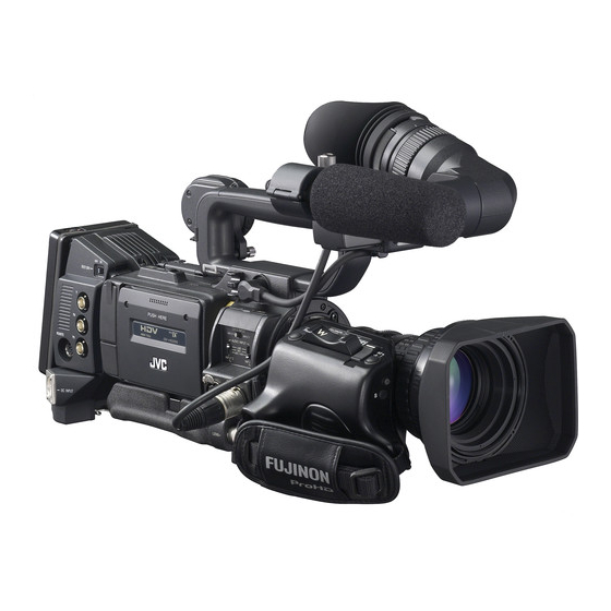
* The illustration shows the GY-HD200U/
GY-HD200E/GY-HD201E HD CAMERA
RECORDER with the provided lens,
viewfinder and microphone attached.
E
INTRODUCTION
CONTROLS,
INDICATORS AND
CONNECTORS
PREPARATIONS
PREPARATIONS
FOR OPERATION
SETTING AND
ADJUSTMENTS
BEFORE SHOOTING
SHOOTING
OPERATION
PLAYBACK MODE
USING EXTERNAL
COMPONENTS
(B)
MENU SCREENS
FEATURES OF THE
CAMERA SECTION
OTHERS
LST0512-001B
Advertisement
Table of Contents

Related Manuals for JVC GY-HD200U


Summary of Contents for JVC GY-HD200U
- Page 1 CAMERA SECTION OTHERS * The illustration shows the GY-HD200U/ GY-HD200E/GY-HD201E HD CAMERA Thank you for purchasing this JVC product. Before operating this RECORDER with the provided lens, viewfinder and microphone attached. device, please read the instructions carefully to ensure the best possible performance.
-
Page 2: Important Safeguards
Important Safeguards Read all of these instructions. Keep these instructions. Heed all warnings. Follow all instructions. Do not use this apparatus near water. Clean only with dry cloth. Do not block any ventilation openings. Install in accor- dance with the manufacturer’s instructions. Do not install near any heat sources such as radia- tors, heat resisters, stoves, or other apparatus (including amplifiers) that produce heat. -
Page 3: Safety Precautions
Replace only with the same or equivalent type.” Consult the dealer or an experienced radio/TV technician for help. CAUTION: CHANGES OR MODIFICATIONS NOT APPROVED BY JVC COULD VOID USER’S AUTHORITY TO OPERATE THE EQUIPMENT. THIS DEVICE COMPLIES WITH PART 15 OF THE FCC RULES. - Page 4 This apparatus is in conformance with the valid European direc- tives and standards regarding electromagnetic compatibility and electrical safety. European representative of Victor Company of Japan Limited is: JVC Technology Centre Europe GmbH P.O. Box 10 05 52 61145 Friedberg Germany...
- Page 5 (Business users) If you wish to dispose of this product, please visit our web page www.jvc-europe.com to obtain information about the take-back of the product. [Other Countries outside the European Union] If you wish to dispose of this product, please do so in accor-...
-
Page 6: Accessories
Thank you for purchasing the JVC HD CAMERA RECORDER. ACCESSORIES These instructions are for the GY-HD200U/CHU, GY- HD200E/CHE and GY-HD201E/CHE. • A lens is included with the GY-HD200U, GY-HD200E and GY-HD201E. • A lens is not included with the GY-HD200CHU, GY- HD200CHE and GY-HD201CHE. -
Page 7: Main Features
• Camera section designed with 3-CCD system for high- MAIN FEATURES quality picture 1/3" 3-CCD with 1,110,000 effective pixels employed. Dig- ital signal processing for reproduction of HDV/DV high- quality picture. • Multi-Zone Auto Iris Detection Circuit Multi-zone auto iris detection circuit ensures optimum iris This device records in HDV format or DV format. -
Page 8: Table Of Contents
Front Section ........11 (GY-HD200U/GY-HD201E only) ....43 Rear Section . - Page 9 Monitoring Audio during Recording ....56 FILE MANAGE Menu Screen ..... .96 Displaying the FILE MANAGE menu screen .
-
Page 10: Introduction
INTRODUCTION • Do not insert an object other than a videocassette in the Precautions for Proper cassette insertion slot. Be sure to close the cassette cover when this device is not to be used for a long period. • Do not set the POWER switch to OFF or remove the power cable during recording or playback. -
Page 11: Routine And Periodical Maintenance
Yardstick 1 to 2 times ev- 1 to 2 times ev- 1 to 2 times ev- • Please use cleaning tape produced by JVC. Do not use use of cleaning ery 5 hours ery 20 to 30 ery 5 hours... -
Page 12: Battery Pack To Be Used
Also it may cause tape-to- tape adhesion (known as blocking). It is recommended • Use JVC’s videocassette tapes marked with the A that videotapes be unspooled and rewound once a year symbol. -
Page 13: Condensation
eocassette, place this device in a tightly sealed vinyl bag, Condensation and then move it to a new environment. To ensure no condensation occurs, allow the temperature of this device in the bag to reach that of the new environ- ment before using it. -
Page 14: Controls, Indicators And Connectors
CONTROLS, INDICATORS AND CONNECTORS 6ZOOM servo control lever ZOOM Lens To operate the servo zoom feature with this lever, set the ZOOM knob b to “S”. • Pressing the “W” section of this lever increases the angle of the lens for a wider shooting angle. •... -
Page 15: Front Section
6[ZEBRA] Zebra switch Front Section When this switch is ON, a zebra pattern is imposed on the viewfinder or LCD areas having luminance levels in accor- dance with the menu settings made for the video signal. This pattern can be used as a reference for manual adjust- ment of the lens iris. -
Page 16: Rear Section
CONTROLS, INDICATORS AND CONNECTORS Connecting the Earphone Cable Rear Section To reduce the emission of unwanted radio waves, be sure to attach the provided clamp filter as shown in the figure below. • Attach the clamp filter as close to this device as possible, as shown in the figure. -
Page 17: Lcd Door
4[TC GENE.] Time code generator setting switch LCD Door Switch for setting the time code generator to preset mode or regeneration mode. It is also used to select the time code run mode when the preset mode is selected. FREE : The preset mode is selected, and the time code run mode becomes the FREE run mode. -
Page 18: Right Side Section
EE monitored. (HDV/DV signal input is possible • When this dial turned upward or downward while the with the GY-HD200U/GY-HD201E.) menu screen is displayed, the cursor (K) also moves The sound to be output is selected with the MONITOR SELECT switch d on page 19. - Page 19 a[STATUS] Status/Menu button d[POWER] Power ON/OFF switch • Pressing this button in the normal screen mode (condi- Switch that turns the power ON/OFF. tion in which the menu screen is not shown) displays a When the power is OFF, “POFF” is displayed in the LCD status screen in the viewfinder or on the LCD monitor.
-
Page 20: Left Side Section
CONTROLS, INDICATORS AND CONNECTORS 4[INPUT1/INPUT2] INPUT1/INPUT2 audio input connec- Left Side Section tors These are audio input connectors for connecting to an external audio device or microphone. • Set the [AUDIO INPUT] switch 3 according to the device to be connected. •... - Page 21 a[IEEE1394] IEEE1394 switch Set according to the image format of the input/output sig- nal and playback signal of the IEEE1394 terminal. HDV : Set to this for HDV format and 1080I CAMERA : Set to this for DV format. b[Y/P ] Component Y/P signal output terminal (BNC ×...
-
Page 22: Top Section
CONTROLS, INDICATORS AND CONNECTORS MEMO Top Section • When FOCUS ASSIST on the LCD/VF[1/4] menu screen is set to ACCU-FOCUS and this button is pressed, ACCU FOCUS functions with FOCUS ASSIST. This makes depth of field shallower, making it easier to focus. •... - Page 23 IEEE1394 connector 0 on page 16, press the CAM/VTR button 5 on page 13 to turn on this indicator. It flashes when the mode is being changed. (HDV/DV signal input is possible with the GY-HD200U, GY-HD201E.) g[FULL AUTO] Full auto shooting (FAS) switch This is the ON/OFF switch for FAS mode.
-
Page 24: Recording And Image Output Formats
CONTROLS, INDICATORS AND CONNECTORS Recording and Image Out- put Formats This device supports HDV and DV image formats. This device also has various output terminals. (Composite, analog component, IEEE1394) During recording and playback, image formats from each of the output terminals are as shown in the table below. Notes about the table (Shaded): Indicates the setting item in the VIDEO FORMAT menu screen. - Page 25 Synchronize the setting for FRAME RATE on the VIDEO FORMAT menu screen with the frame rate of the IEEE1394 input signal. When playing back 1080i 60/50 HDV images recorded on the DR-HD100 (Only with the GY-HD200U and GY-HD201E) Component Out...
-
Page 26: Indications On The Lcd Monitor And In The Viewfinder
CONTROLS, INDICATORS AND CONNECTORS The contents of the status display are divided into those for Indications on the LCD the Camera mode and those for the VTR mode. • Each time the STATUS button is pressed in the Camera Monitor and in the View- mode, one of 5 status screens is displayed. -
Page 27: Status Screens In The Camera Mode
Status Screens in the Camera Mode 266S DD STATUS 0 Screen STATUS 0 1 Event Indication When the Gain or Shutter Speed is changed manually, the setting condition is displayed for about 3 seconds at the time the change is made. •... -
Page 28: Indications On The Lcd Monitor
CONTROLS, INDICATORS AND CONNECTORS Indications on the LCD Monitor and in the Viewfinder (Cont’d) Setting Status Contents of Indications FF/REW button was pressed in CAMERA SWITCH TO VTR MODE mode When REC/VTR trigger button is pressed while 1080I REC INVALID! 1080I CAMERA in the VIDEO FORMAT[1/2] menu screen is set to ON and DR-HD100 is not connected... - Page 29 STATUS 1 Screen STATUS 1 In addition to the information on the STATUS 0 screen, this screen displays the following items. Item Contents VIDEO FORMAT display Displays the currently selected video format. Allows you to select the REC item on the VIDEO FORMAT[1/2] menu screen. X See page 74. You can switch this display ON/OFF using the VIDEO FORMAT item on the LCD/VF[3/4] menu screen.
- Page 30 CONTROLS, INDICATORS AND CONNECTORS Indications on the LCD Monitor and in the Viewfinder (Cont’d) Item Contents Audio sampling frequency in- 32 K : Indicated when the AUDIO MODE item on the AUDIO/MIC[1/2] menu screen is set to 32 K. (Audio dication is recorded with 12-bit, 32 kHz sampling.) 48 K : Indicated when the AUDIO MODE item on the AUDIO/MIC[1/2] menu screen is set to 48 K.
- Page 31 STATUS 2 Screen STATUS 3 Screen STATUS 2 This screen displays the camera setup statuses. Event display is not available while this screen is displayed. Indication Indication Contents F CAM1 [********], CAM2-4 [********], and EXT1 - 4 [********] * indicates SUB NAME X See pages 96-98. FILE FILE A F symbol is displayed when a menu setting read from LOAD FILE was changed.
-
Page 32: Status Screen In Vtr Mode
CONTROLS, INDICATORS AND CONNECTORS Indications on the LCD Monitor and in the Viewfinder (Cont’d) Status Screen in VTR MODE Item Contents VIDEO FORMAT display Displays the video format recorded on the tape when in VTR mode. Also displays the video format of the HDV/DV input signal. -
Page 33: Magnified Status Indications On The Lcd Monitor
During recording in HDV format, the data of internal clock is displayed. (HDV/DV signal input is possible with the GY-HD200U, GY-HD201E.) Whether or not the date and time should be displayed and the display style are set on the TIME/DATE menu screen. -
Page 34: Auto White Balance Indication (Camera Mode Only)
CONTROLS, INDICATORS AND CONNECTORS Indications on the LCD Monitor Alarm Message Display and in the Viewfinder (Cont’d) • The following alarm messages are displayed while the STA- TUS (0, 1, 4) screen is shown in the Camera mode, or a STA- TUS screen is shown in the VTR mode. -
Page 35: Switching Between The Lcd Screen And Viewfinder Display
SAFETY ZONE 2.35:1CE 2.35:1CH CENTER MARK DV-60I Cannot be selected DV-50I DV-24P DV-24PA 16:9 DV-25P HDV-HD60P HDV-HD50P HDV-HD30P HDV-HD25P [16:9] HDV-HD24P 1080-60I 1080-50I Switching between the LCD Screen and Viewfinder Display When the LCD+VF item in the LCD/VF[4/4] menu is set to OFF, the LCD monitor and viewfinder (VF) displays are as shown below. -
Page 36: Preparations
2/3 Zoom Lens 16mm Cine Lens HZ-CA13U Dolly An HZ-FM13 cannot be used with a Th16 × 5.5BRMU or S14 × 7.3B12/U zoom lens. Use a FUJINON focus manual unit (FMM-8, CFH-3, CFC-12-990). For details, please consult your JVC authorized dealer. -
Page 37: Attaching The Zoom Lens
1. 3. Knob Microphone Attaching the Zoom Lens Loosen the mount ring. Microphone Attach the lens with its pin aligned with the hole in the holder mount. Tighten the mount ring. Connect the cable connector. Clamp the lens cable. Clamp Hole INPUT1, 2 connector How to Attach the View-... -
Page 38: Inserting An Sd Memory Card
PREPARATIONS Close the SD memory card cover. How to Attach the Viewfinder (Cont’d) Cutout About the Viewfinder Cable Attach the viewfinder cable to the clamp 7 on page 14. To reduce the emission of unwanted radio waves, be sure to attach the provided core filter as shown in the figure below. -
Page 39: Attaching The Tripod Base (Optional)
CAUTION Attaching the Tripod Base • The front base mount may be locked while the pin of the tripod base is not inserted into the hole on the rear base (Optional) mount of this device. Therefore, after mounting, make sure that these parts are engaged properly. •... -
Page 40: Ac Operation
PREPARATIONS AC Operation Charging the Built-in Battery The built-in, rechargeable backup battery retains the date and time and the time code data. The built-in battery is constantly being charge whenever this This device is operable with AC power supply or battery device is connected to a power supply, but it gradually dis- pack. -
Page 41: Battery Operation
Use only the recommended batteries. If a heavy battery is used, the battery may fall out depend- ing on the way the HD camera recorder is used. GY-HD200U Use an Anton Bauer battery. Attaching the Battery Slide the battery down until it clicks and locks. -
Page 42: Precautions For The Battery Operation
PREPARATIONS • When you use an Anton Bauer battery, the remaining Battery Operation battery (capacity or time) can be displayed in the STA- TUS 1 screen of the LCD screen or viewfinder. Set BAT- (Cont’d) TERY INFO. on the LCD/VF[3/4] menu screen to CAPA% or TIME to display the remaining battery. -
Page 43: Preparations For Operation
PREPARATIONS FOR OPERATION Turning the Power ON Turning the Power OFF Place this device in the record-standby or STOP mode. Set the POWER switch to OFF. Remove the battery pack or the power supply to the DC INPUT connector. (When the camera is not going to be Turning the Power ON used for a longer period.) CAUTION... -
Page 44: Loading/Unloading The Cassette
PREPARATIONS FOR OPERATION Loading/Unloading the Unloading the Cassette Cassette Turn the POWER switch to ON. When this device is in shooting standby mode or stop mode, slide the EJECT switch to the side and wait until the videocassette cover opens completely. Cassette Loading •... -
Page 45: Setting And Displaying The Date And Time
Setting and Displaying the TC/UB/CLOCK menu screen Date and Time The date and time of the built-in clock should be set. Pow- ered by the built-in backup battery the set date and time data continue to count even when the power is switched off. •... -
Page 46: Setting The Date And Time
4Press the SHUTTER dial in sync with a time signal to are displayed in HDV format. enter the date and time precisely. (GY-HD200U/GY-HD201E only) When all the settings are completed, rotate the SHUT- TER dial to align the cursor with the PAGE BACK item, and then press the SHUTTER dial. -
Page 47: Displaying Time Code
Displaying Time Code Time code input entered the IEEE1394 connector (GY-HD200U/ GY-HD201E only) This device records SMPTE-standard (NTSC) or EBU-stan- Pressing the STOP button for 1 second in the EJECT or stop dard (PAL) time codes and user’s bits. In the play mode or mode displays the DV input time code data or user’s bit data... -
Page 48: Presetting And Recording Of Time Code
PREPARATIONS FOR OPERATION TC/UB/CLOCK menu screen (FRAME RATE: 60/30 and Presetting and Recording Use the DROP FRAME item to select the framing mode of Time Code for the time code generator. DROP : The time code generator’s running method is set the drop frame mode. -
Page 49: Presetting Time Code Data
Presetting time code data Presetting user’s bit data The time code and user’s bit data are preset on the TC/UB/ The user’s bit data are preset with the UB PRESET item on CLOCK menu screen. the TC/UB/CLOCK menu screen. The method for setting is the same as the method for setting Display the TC/UB/CLOCK menu screen. -
Page 50: Presetting The Time Code From The Lcd Screen
PREPARATIONS FOR OPERATION Presetting the Time Code from the LCD Screen The time code can be preset directly from the LCD screen without opening the TC/UB/CLOCK menu screen. CAUTION PRESET mode is not available in the following. Blink • TC GENE. switch is set to REGEN. •... -
Page 51: Recording Time Codes In Continuation Of
Recording Time Codes in Playing Back Time Code Continuation of Time Codes Recorded on Tape This device features a time code reader. During playback, the time code or user’s bit data recorded on the tape is dis- This device also incorporates a time code reader. Therefore, played on the LCD screen or viewfinder status screen. -
Page 52: Synchronizing With The Time Code Of
Slide the IEEE1394 switch to the [DV] side. switch to the [DV] side. IEEE1394 cable You can use the GY-HD200U or GY-HD201E as a slave unit. Status display You cannot use the GY-HD200E as a slave unit. DTCG 00 : 00 : 00 : 00... -
Page 53: Screen Adjustment
Screen Adjustment Viewfinder Adjustment Direction of the Viewfinder LCD monitor direction, angle, screen brightness, etc. can be adjusted. Adjust the position and angle of the viewfinder. Diopter Adjustment Adjusting the Direction and Angle of the Rotate the eyepiece focusing ring until the viewfinder screen LCD monitor image is clearly visible. -
Page 54: Back Focus Adjustment
PREPARATIONS FOR OPERATION Set the IRIS mode switch to M (Manual). Back Focus Adjustment Set the zoom mode to M (Manual). Open the iris by turning the iris ring. If the illumination is too strong, reduce it or move to a darker place. -
Page 55: White Balance Adjustment
• ERROR: LOW LIGHT (Insufficient illumination) White Balance Adjustment Displayed when the illumination is dim. Increase the illumi- nation and then re-adjust the white balance. • ERROR: OVER LIGHT (Excessive illumination) Displayed when the light is excessively bright. Decrease the illumination and then re-adjust the white balance. Since the color of light (color temperature) varies depending on the light source, it is necessary to re-adjust the white balance when the main light source illuminating the subject changes. -
Page 56: White Shading Adjustment
PREPARATIONS FOR OPERATION Setting in the WHITE BALANCE screen is performed as fol- White Shading Adjustment lows. Selecting an item Turn the SHUTTER dial to align the cursor (j) with the desired item, and press the SHUTTER dial. • The item is selected and the setting value blinks. It is necessary to perform this adjustment to the camera Changing the setting value when attaching a lens that is different from the previously... -
Page 57: Setting And Adjustments Before Shooting
SETTING AND ADJUSTMENTS BEFORE SHOOTING Turn the SHUTTER dial, change the setting and push the Setting the Video Format SHUTTER dial. • The setting stops flashing and is temporarily set. • Move the cursor (K) to the EXECUTE item and EXE- CUTE flashes. -
Page 58: Camera Settings
SETTING AND ADJUSTMENTS BEFORE SHOOTING ASPECT item Camera Settings 4:3 TV Set the switch positions. 16:9 TV A. [GAIN] switch: Set to L ( 0 dB). B. [WHT. BAL] (Auto White Balance) switch: Set to A or Set the lens’ iris mode switch to “A” (Auto iris side). Select the ND filter. -
Page 59: Audio Input Signal Selection
MEMO Audio Input Signal Selec- You can select the normal input level for MIC and MIC+48V in the INPUT1, 2 MIC REF. item on the AUDIO/MIC[1/2] tion menu screen. This device is provided with the INPUT1 connector and the Adjusting Audio during Recording INPUT2 connector for audio input. -
Page 60: Monitoring Audio During Recording
SETTING AND ADJUSTMENTS BEFORE SHOOTING • The loudspeaker or earphone outputs an alarm tone in the Audio Input Signal Selection case of an abnormal condition occurring in this device. An alarm tone is also output when the tape end is reached (Cont’d) or when the battery is running down. -
Page 61: Shooting Operation
SHOOTING OPERATION MEMO Basic Recording Opera- The way the FRONT TALLY and the BACK TALLY lamps flash differ depending on what you set in the FRONT tion TALLY and BACK TALLY items on the OTHERS[1/2] menu screen. X See page 93. Set the POWER switch to ON. -
Page 62: If The Record-Standby Mode Continues
SHOOTING OPERATION • The recorded contents can be checked on the LCD moni- Basic Recording Operation tor, in the viewfinder or on a monitor connected to the video signal output connectors. (Cont’d) In the record-standby mode, press the RET button on the camera lens section. -
Page 63: Header Rec Function
HEADER REC Function When the REC/VTR trigger button is pressed while the STOP button is pressed, this function first records the color bar video and the test tone (1 kHz sine-wave) of the built-in signal generator at the beginning of the tape. Then it records the black video signal and the mute audio signal for the duration specified in advance. - Page 64 SHOOTING OPERATION While pressing the STOP button, press the REC/VTR HEADER REC Function trigger button. • The tape automatically rewinds to the beginning, and (Cont’d) HEADER REC operation starts from the beginning of the tape. After HEADER REC recording is performed for the specified duration only, the Record-Standby mode is How to set the HEADER REC menu screen engaged automatically.
-
Page 65: Playback Mode
PLAYBACK MODE • When the automatic tracking function is activated at the Playback Procedure start of the playback mode, digital noise may appear in the playback image. • This device does not allow manual tracking adjustment. • When playing back a tape that was recorded on another unit, digital noise may appear during playback. -
Page 66: Outputting Audio
PLAYBACK MODE Display the AUDIO menu screen. Outputting Audio Select the AUDIO item on the TOP MENU screen. Set the AUDIO menu screen. • PB AUDIO CH [DV] Items CH1/2 : To reproduce the sound (CH-1, CH-2) recorded during shooting. Setting : To reproduce the sound recorded during shooting (CH-1, CH-2) and the after-... -
Page 67: Using External Components
USING EXTERNAL COMPONENTS Displaying Alarms Connecting the Video • CHANGE 1394 SWITCH Displayed when the setting for the input/output video format Signal Cables from the IEEE1394 connector and the setting for the IEEE1394 switch are different. Set the IEEE1394 switch so it matches the video format. Connecting the IEEE1394 Cable To reduce the emission of unwanted radio waves, be sure to attach the provided clamp filter as shown in the figure below. -
Page 68: Dubbing With Av Devices
Set the audio output. X See page 62. Dubbing with AV Devices Set the AUDIO menu screen. X See page 84. AUDIO menu screen By connecting the video signal output terminal and the AUDIO OUTPUT terminal on this device to an AV device, analog signal dubbing is possible. -
Page 69: Hdv/Dv Dubbing
Set the PB TAPE item on the VIDEO FORMAT menu HDV/DV Dubbing screen. X See page 76. Select whether to automatically detect the playback tape video format or play back only a particular format. Normally, use the “AUTO” setting. VIDEO FORMAT menu screen Connecting this device to another video component equipped with HDV/DV connector (IEEE1394 standard) using a IEEE1394 cable (optional) enables dubbing of digital... -
Page 70: See
When Using the GY-HD200U/GY-HD201E as Recording Unit (Dubbing From Another Videocassette) Set the IEEE1394 switch on left side of the GY-HD200U/ GY-HD201E. : When dubbing in DV format HDV : When dubbing in HDV format Connect the units with the IEEE1394 cable. -
Page 71: Backup Recording
Backup unit Backup Recording • Place in HDV/DV signal input mode. * Depending on the used component, it may be neces- sary to set “REMOTE SELECT”. • When BR-HD50 is used, set the Backup Recording function to OFF. Also, set REM SEL HDV/DV in the REMOTE[1/2] menu Backup Recording of this Device’s Cam- of the BR-HD50 to ON or LOC+REM. -
Page 72: (Rm-Lp55/Rm-Lp57/Rm-Lp25)
• Attach the clamp filter included with the remote control unit to the remote cable.(The clamp filter can be substituted 12dB with the clamp filter included with this device.) 15dB Consult your JVC dealer if you do not have a clamp filter. 18dB LOLUX CAUTION –3dB –6dB... -
Page 73: 1080I Recording
TWhen frame rate is set to “24”, 1080I CAMERA cannot be set. Table 2 When playing back 1080i 60/50 HDV images VTR button (1394 REC TRIGGER B SYNCRO) recorded on the DR-HD100 (Only with the GY-HD200U and GY-HD201E) Component Out • Playback of the recorded files in the DR-HD100... -
Page 74: Menu Screens
MENU SCREENS Menu Screen Configura- tion The Menu Screen consists of multiple layers of menu screens as shown below. The menu screen to be set is selected from the TOP MENU in accordance with the function or purpose. The items on the menu screens differ with the Camera mode and the VTR mode. The contents of set items are stored in this device’s memory and are retained even when the power is turned off. - Page 75 VTR Mode/IEEE1394 Input Mode (HDV/DV signal input is possible with the GY-HD200U, GY-HD201E.) 1 0 8 0 i C A M E R A O F F V F S I G N A L R G B TOP MENU screen (VTR)
-
Page 76: Setting Menu Screens
MENU SCREENS Select the menu screen to be set. Setting Menu Screens Rotate the SHUTTER dial to align the cursor (K) with the menu screen to be set, and then press the SHUTTER dial. • The selected menu screen appears. Item Setting Make the settings while observing the LCD monitor or the... -
Page 77: Top Menu Screen
TOP MENU Screen Different menu screens are displayed depending on whether this device is in the Camera mode or in the VTR mode. In the VTR mode, the CAMERA OPERATION, CAMERA PROCESS and SWITCH MODE menu screens are not displayed. Item Function VIDEO FORMAT.. -
Page 78: Video Format[1/2] Menu Screen
MENU SCREENS VIDEO FORMAT[1/2] Menu Screen The VIDEO FORMAT menu screen consists of two screens (1/2 screen, 2/2 screen). In VTR mode, this screen consists of one screen. * This is not displayed in VTR mode. Item Function/Setting (bold characters indicate initial settings) FRAME RATE Sets the frame rate for shooting. - Page 79 * This is not displayed in VTR mode. Item Function/Setting (bold characters indicate initial settings) ASPECT* Sets the screen size for the recording video signal. (Can only be displayed and set in camera mode) : Outputs the video with an aspect ratio of 4:3. 16:9 : Outputs the video with an aspect ratio of 16:9.
-
Page 80: Video Format[2/2] Menu Screen
MENU SCREENS VIDEO FORMAT[2/2] Menu Screen * This is not displayed in VTR mode. Item Function/Setting (bold characters indicate initial settings) PB TAPE Selects whether to automatically detect the playback tape video format or play back only a particular format. Normally, use the “AUTO”... -
Page 81: Camera Operation Menu Screen
CAMERA OPERATION Menu Screen The CAMERA OPERATION menu screen is only displayed in the Camera mode. Item Function/Setting (bold characters indicate initial settings) For adjusting the image level when using auto iris, “ALC” or “EEI”. AE LEVEL Increase value : Increases level. Decrease value : Decreases level. -
Page 82: Camera Process[1/2] Menu Screen
MENU SCREENS CAMERA PROCESS[1/2] Menu Screen The CAMERA PROCESS menu screen consists of two screens. (1/2 screen, 2/2 screen) The CAMERA PROCESS menu screen is only displayed in camera mode. Item Function/Setting (bold characters indicate initial settings) MASTER BLACK Adjusts the pedestal level (master black) that serves as the reference black. Increase the number : Raises the pedestal level. -
Page 83: Camera Process[2/2] Menu Screen
CAMERA PROCESS[2/2] Menu Screen Item Function/Setting (bold characters indicate initial settings) BLACK Changes the gain in dark areas. Change this depending on the video signal being shot. NORMAL : Normal status STRETCH : Enhances the dark areas of the video so the contrast between light and dark is more visible by stretching the signal only in the dark areas. -
Page 84: Advanced Process Menu Screen
MENU SCREENS ADVANCED PROCESS Menu Screen Item Function/Setting (bold characters indicate initial settings) CINEMA : Turns the function OFF. : Sets the gamma characteristics and color matrix close to the characteristics of a movie screen. (The monitor image is movie-quality. This setting is not intended for film output.) MEMO When this item is set to “ON”, “[CINE]”... -
Page 85: Color Matrix Adjust Menu Screen
COLOR MATRIX ADJUST Menu Screen Item Function/Setting (bold characters indicate initial settings) R GAIN For manually adjusting the shading of the R axis of the color matrix (red and cyan). Increase the number : Enhances red and cyan. Decrease the number : Reduces red and cyan. [Settings: MIN (–5), –4 - NORMAL (0) - 4, MAX (5)] R ROTATION For manually adjusting the color phase of the R axis of the color matrix (red and cyan). -
Page 86: White Balance Menu Screen
MENU SCREENS WHITE BALANCE Menu Screen Item Function/Setting (bold characters indicate initial settings) Adjusts the R (red) component when in AWB (Auto White Balance) mode. WHITE PAINT<R> Increase the number : Strengthens the red. Decrease the number : Weakens the red. [Settings: MIN (–32), –31 - NORMAL (0) - 30, MAX (31)] MEMO •... -
Page 87: Switch Mode Menu Screen
SWITCH MODE Menu Screen The SWITCH MODE menu screen is only displayed in camera mode. Item Function/Setting (bold characters indicate initial settings) SHUTTER Sets the fixed value (STEP) for values that can change using the SHUTTER dial on the right panel or the VARIABLE used when shooting computer monitors. -
Page 88: Audio/Mic[1/2] Menu Screen
MENU SCREENS AUDIO/MIC[1/2] Menu Screen The AUDIO/MIC menu screen consists of two screens (1/2 screen, 2/2 screen). In VTR mode, the screen changes to the AUDIO menu screen. * This is not displayed in VTR mode. Item Function/Setting (bold characters indicate initial settings) TEST TONE Sets whether to output a test audio signal (1 kHz, –20dBFS or –12dBFS) during color bar output. -
Page 89: Audio/Mic[2/2] Menu Screen
AUDIO/MIC[2/2] Menu Screen In VTR mode, the screen changes to the AUDIO menu screen. * This is not displayed in VTR mode. Item Function/Setting (bold characters indicate initial settings) AUDIO MONITOR Selects whether stereo or mixed audio is output from the PHONES jack when the MONITOR SELECT switch is set to BOTH. -
Page 90: Lcd/Vf[1/4] Menu Screen
MENU SCREENS LCD/VF[1/4] Menu Screen The LCD/VF menu screen consists of four screens. (1/4 screen, 2/4 screen, 3/4 screen, 4/4 screen) The LCD/VF[1/4] menu screen can only be set in camera mode. In VTR mode, this screen consists of two screens. (1/2 screen, 2/2 screen) Item Function/Setting (bold characters indicate initial settings) ZEBRA... -
Page 91: Lcd/Vf[2/4] Menu Screen
LCD/VF[2/4] Menu Screen The LCD/VF[2/4] menu screen can only be set in camera mode. Item Function/Setting (bold characters indicate initial settings) LCD MIRROR MODE Sets the image display method when the LCD monitor is in counterview position. NORMAL : Image is displayed without inverting. MIRROR : Inverted image is displayed. -
Page 92: Lcd/Vf[3/4] Menu Screen
MENU SCREENS LCD/VF[3/4] Menu Screen [1/2] screen is displayed in the VTR mode. Item Function/Setting (bold characters indicate initial settings) VIDEO FORMAT Selects whether to display the video format in the status display on the LCD monitor or the viewfinder. (Camera mode: STATUS 1 screen, VTR mode: STATUS screen) : Displays the video format. -
Page 93: Lcd/Vf[4/4] Menu Screen
LCD/VF[4/4] Menu Screen [2/2] screen is displayed in the VTR mode. * This is not displayed in VTR mode. Item Function/Setting (bold characters indicate initial settings) LCD+VF Selects the LCD monitor and viewfinder display switching method. : Viewfinder always displayed the image. : Turns off the viewfinder display when the LCD monitor is opened. -
Page 94: Tc/Ub/Clock Menu Screen
MENU SCREENS TC/UB/CLOCK Menu Screen Time codes (TC) and user’s bits (UB) can be set on this screen. Date and time is set on the TIME/DATE screen that can be reached from this screen. Item Function/Setting (bold characters indicate initial settings) TC PRESET To preset the time code, align the cursor with this position and then press the SHUTTER dial. -
Page 95: Header Rec Menu Screen
HEADER REC Menu Screen The HEADER REC menu screen is used for settings related to the HEADER REC function. X See page 59. Item Function/Setting (bold characters indicate initial settings) START KEY Sets whether the HEADER REC operation should be executed when the REC/VTR trigger button is pressed while the STOP button is pressed. -
Page 96: Time/Date Menu Screen
MENU SCREENS TIME/DATE Menu Screen Item Function/Setting (bold characters indicate initial settings) DISPLAY Sets whether the date and time are shown in the status display on the LCD monitor or in the viewfinder. : Not displayed. : Displayed. When a tape with time and date not recorded is played back, there will be no display of time and date even when this item is set to ON. -
Page 97: Others[1/2] Menu Screen
OTHERS[1/2] Menu Screen The OTHERS menu screen consists of two screens (1/2 screen, 2/2 screen) Item Function/Setting (bold characters indicate initial settings) ANALOG OUT CHAR. Sets whether or not to display characters such as status and menus on the screen for the [Y/P ] and [VIDEO OUT] terminals. -
Page 98: Others[2/2] Menu Screen
MENU SCREENS OTHERS[2/2] Menu Screen * This is not displayed in VTR mode. Item Function/Setting (bold characters indicate initial settings) 1394 REC TRIGGER* Sets how to control the REC trigger command output from the IEEE1394 connector. (Can be displayed and set in camera mode) Set this when recording a backup of the HDV/DV signal from this device onto another device. - Page 99 * This is not displayed in VTR mode. Item Function/Setting (bold characters indicate initial settings) DR-HD100 A.OFF* Selects whether or not to turn OFF the DR-HD100 (HDD unit by FOCUS enhancements) when this device is turned OFF. : Power does not turn OFF. : Power turns OFF with this device.
-
Page 100: File Manage Menu Screen
MENU SCREENS FILE MANAGE Menu Displaying the FILE MANAGE menu screen Screen Select the FILE MANAGE.. item on the TOP MENU screen. You can perform the following operations in the FILE MAN- AGE menu screen. • Settings corresponding to shooting conditions can be read Loading a menu settings file immediately with the following read-only files. -
Page 101: Saving Settings
Turn the SHUTTER dial, bring the cursor (K) to the Saving settings STORE item and press the SHUTTER dial. • EXECUTE (if the file already exists, “OVERWRITE”) flashes. Select the STORE FILE.. item on the FILE MANAGE menu screen. Turn the SHUTTER dial, bring the cursor (K) to SELECT and press the SHUTTER dial. -
Page 102: Resetting The Menu Settings To The Factory Settings
MENU SCREENS MEMO FILE MANAGE Menu Screen Even if CAM1, CAM2, CAM3, or CAM4 are reset, the cur- (Cont’d) rent settings are not reset. To reset the currently set values, select “CURRENT”. Initializing (formatting) an SD mem- Resetting the menu settings to the ory card factory settings Before initializing (formatting) a card:... -
Page 103: Features Of The Camera Section
FEATURES OF THE CAMERA SECTION Move the cursor (K) to the SKIN COLOR DET. item, How to Use Skin Detail press the SHUTTER dial and select EXECUTE to switch to skin color detection mode. Shoot so that the color area you want to detect within the detection area frame is input. -
Page 104: Using The Skin Detail Function
FEATURES OF THE CAMERA SECTION How to Use Skin Detail (Cont’d) Using the Skin Detail Function To use the skin detail function set on the SKIN COLOR ADJUST screen, select “ON” for the SKIN DETECT item on the CAMERA PROCESS[1/2] menu screen. In addition, you can use the LEVEL item to set three levels of suppression of skin color area detail enhancement in the video signal. -
Page 105: Outputting Color Bars
Outputting Color Bars This device can output three types of color bars, depending on the camera settings. NTSC standard : Outputs color bars compliant with the SMPTE standard. PAL standard : Outputs color bars compliant with the EBU standard. 16:9 screen : Outputs multi-format color bars. -
Page 106: Warnings And Responses
OTHERS Warnings and Responses Warnings are displayed on the LCD monitor or the viewfinder if there was a mistaken operation, if the battery or tape is low, or if there is a problem on the VTR. In addition, if the tape or battery is low or the VTR has a problem, the tally lamp flashes (or lights) and an alarm is output from the monitor speaker or PHONES jack. - Page 107 Cannot play back a copyguarded tape. FAN MOTOR HOUR Over the prescribed fan motor usage time. Please contact your local dealer or JVC. PUSH CASSETTE The videocassette cover is not firmly shut. Lightly push the top center of the videocassette cover.
- Page 108 Tape cannot be unloaded. stances. Please consult the person in UNLOADING FAILURE charge of professional video equip- 4100 Irregularity with eject operation. ment at your nearest JVC-authorized CASSETTE EJECT FAILURE service agent. 5605 - 5609 Tape is cut. Operation stops.
- Page 109 TALLY lamp Blinks when remaining battery power or tape is low. (Only in Camera mode) Blinking Pattern Remaining Battery/Tape Slow blinking • Remaining battery power is low. (once per sec.) • Remaining tape time is equivalent to less than 3 minutes. Fast blinking •...
-
Page 110: Troubleshooting
OTHERS Troubleshooting Symptoms Remedy Power cannot be switched ON. • Is power supply connected correctly? • Is battery pack recharged? • Was the power turned ON immediately after being turned OFF? Wait at least 5 seconds before turning the power ON again once it has been turned OFF. -
Page 111: How To Display The Hour Meter
How to Display the Hour Meter The drum and fan motor usage times are displayed in the DRUM HOUR item and the FAN HOUR items on the OTH- ERS[2/2] menu screen as the hour meters on this device. Use as an estimate for regular maintenance. X See page 7. Turn the POWER switch ON. -
Page 112: Specifications
: 720/24p, 720/25p, 720/30p, 720/ Warranty Card 50p, 720/60p (U/E model), 480/24p, (USA and Canada only) 480/60i (U model), 576/25p, 576/50i (E model), 1080/60i (IEEE1394 For details, consult your JVC dealer. output only), 1080/50i (IEEE1394 output only) Video Format: [HDV] Video signal : HDV720p format, 8-bit, 18.3 Mbps... -
Page 113: External Dimensions
EXTERNAL DIMENSIONS (unit: mm) * Design and specifications are subject to change without notice. - Page 114 © 2008 Victor Company of Japan, Limited LST0512-001B...