Sony DCR-TRV240 Service Manual
Digital video camera recorder
Hide thumbs
Also See for DCR-TRV240:
- Operating instructions manual (212 pages) ,
- Brochure (2 pages) ,
- Limited warranty (1 page)
Table of Contents
Advertisement
Quick Links
DCR-TRV240/TRV340
SERVICE MANUAL
Level 2
Ver 1.0 2002. 01
On the VC-276 board
This service manual provides the information that is premised the
circuit board replacement service and not intended repair inside the
VC-276 board.
Therefore, schematic diagram, printed wiring board, waveforms,
mounted parts location and electrical parts list of the VC-276 board
are not shown.
The following pages are not shown.
Schematic diagram ..................................... Pages 4-29 to 4-78
Printed wiring board .................................... Pages 4-79 to 4-82
Waveforms and mounted parts location ..... Pages 4-85 to 4-89
Electrical parts list ....................................... Pages 6-14 to 6-25
Video camera
recorder
System
Video recording system
2 rotary heads
Helical scanning system
Audio recording system
Rotary heads, PCM system
Quantization: 12 bits (Fs 32 kHz,
stereo 1, stereo 2), 16 bits
(Fs 48 kHz, stereo)
Video signal
NTSC color, EIA standards
Recommended cassette
Hi8/Digital8 video cassette
Recording/playback time (using
120 min. Hi8 video cassette)
SP mode: 1 hour
LP mode: 1 hour and 30 minutes
Fast-forward/rewind time (using
120 min. Hi8 video cassette)
Approx. 5 min.
Viewfinder
Electric Viewfinder, Monochrome
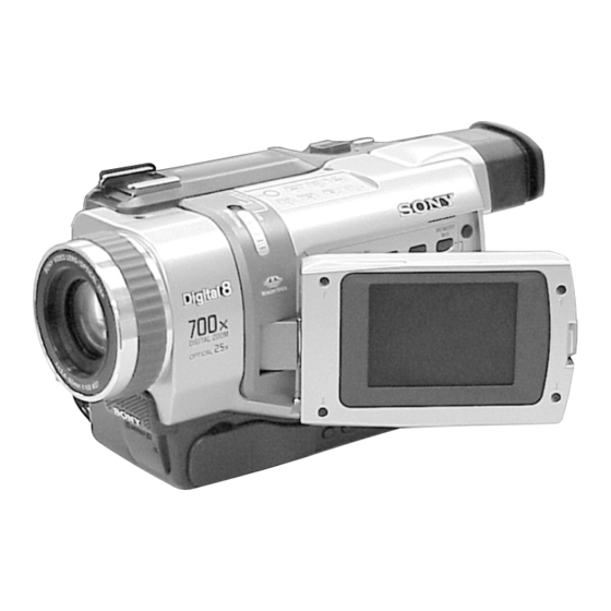
Photo : DCR-TRV340
SPECIFICATIONS
Image device
3 mm (1/6 type CCD)
(Charge Coupled Device)
Gross: Approx. 460 000 pixels
Effective: Approx. 290 000 pixels
Lens
Combined power zoom lens
Filter diameter 37 mm (1 1/2 in.)
25× (Optical), 700× (Digital)
Focal length
2.4 – 60 mm (1/8 – 2 3/8 in.)
When converted to a 35 mm still
camera
42 – 1 050 mm (1 11/16 – 41 3/8
in.)
Color temperature
Auto
Minimum illumination
4 lx (lux) (F 1.6)
0 lx (lux) (in the NightShot mode)*
* Objects unable to be seen due to
the dark can be shot with
infrared lighting.
DIGITAL VIDEO CAMERA RECORDER
Hong Kong Model
For MECHANISM ADJUSTMENT, refer to the
"8mm Video MECHANICAL ADJUSTMENT
MANUAL
IX
M2000 MECHANISM " (9-929-
861-11).
Input/output
connectors
S video input/output
4-pin mini DIN
Luminance signal: 1 Vp-p,
75 Ω (ohms), unbalanced
Chrominance signal: 0.286 Vp-p,
75 Ω (ohms), unbalanced
Audio/Video input/output
AV MINIJACK, 1 Vp-p, 75 Ω
(ohms), unbalanced, sync negative
327 mV, (at output impedance
more than 47 kΩ (kilohms))
Output impedance with less than
2.2 kΩ (kilohms)/Stereo minijack
(ø 3.5 mm)
Input impedance more than 47 kΩ
(kilohms)
Headphone jack
Stereo minijack (ø 3.5 mm)
USB jack
mini-B
RMT-814
US Model
Canadian Model
E Model
DCR-TRV240/TRV340
Korea Model
Tourist Model
Argentina Model
Brazilian Model
DCR-TRV340
M2000 MECHANISM
LANC jack
Stereo mini-minijack (ø 2.5 mm)
MIC jack
Stereo minijack (ø 3.5 mm)
DV input/output
4-pin connector
LCD screen
Picture
6.2 cm (2.5 type)
50.3 × 37.4 mm (2 × 1 1/2 in.)
Total dot number
61 600 (280 × 220)
— Continued on next page —
Advertisement
Table of Contents

Related Manuals for Sony DCR-TRV240


Summary of Contents for Sony DCR-TRV240
- Page 1 DCR-TRV240/TRV340 RMT-814 SERVICE MANUAL US Model Canadian Model Level 2 E Model Ver 1.0 2002. 01 Hong Kong Model DCR-TRV240/TRV340 Korea Model Tourist Model Argentina Model Brazilian Model Photo : DCR-TRV340 DCR-TRV340 M2000 MECHANISM On the VC-276 board For MECHANISM ADJUSTMENT, refer to the “8mm Video MECHANICAL ADJUSTMENT...
- Page 2 CRITIQUES POUR LA SÉCURITÉ DE FONCTIONNEMENT. NE COMPONENTS WITH SONY PARTS WHOSE PART NUMBERS REMPLACER CES COMPOSANTS QUE PAR DES PIÈSES SONY APPEAR AS SHOWN IN THIS MANUAL OR IN SUPPLEMENTS DONT LES NUMÉROS SONT DONNÉS DANS CE MANUEL OU PUBLISHED BY SONY.
- Page 3 2-pin conversion adaptor (1) Commander (2) DCR-TRV340 : Tourist model 5 A/V connecting cable (1) qs 2-pin conversion adaptor (1) 6 Shoulder strap (1) DCR-TRV240 : E, Hong Kong/ TRV340 : E, Hong Kong model Table for difference of function Model DCR-TRV240 DCR-TRV340...
-
Page 4: Table Of Contents
DCR-TRV240/TRV340 TABLE OF CONTENTS SERVICE NOTE Recording video or TV programs ········································ 1-21 Inserting a scene from a VCR – Insert Editing ···················· 1-22 POWER SUPPLY DURING REPAIRS ····························· 7 Viewing images recorded on a tape on your computer TO TAKE OUT A CASSETTE WHEN NOT EJECT (Windows users only) ·······················································... - Page 5 1-2. INITIALIZATION OF 8, A, B, C, D, E, F, 1B, 1C, 1F 3-4. OVERALL BLOCK DIAGRAM (4/5) ··························· 3-7 PAGE DATA ···································································· 5-8 3-5. OVERALL BLOCK DIAGRAM (5/5)(DCR-TRV240) ···· 3-9 1-2-1. INITIALIZATION OF D PAGE DATA 3-5. OVERALL BLOCK DIAGRAM (5/5)(DCR-TRV340) ··· 3-11 (DCR-TRV240) ·······························································...
- Page 6 DCR-TRV240/TRV340 2-1-1. OPERATING WITHOUT CASSETTE ························ 5-34 Emergence Memory Address ········································ 5-55 2-1-2. TAPE PATH ADJUSTMENT ········································ 5-34 2-1. EMG Code (Emergency Code) ····································· 5-55 Preparations for Adjustment ·········································· 5-34 2-2. MSW Code ···································································· 5-56 2-2. DIGITAL8 MODE ························································ 5-35 Bit Value Discrimination ···············································...
-
Page 7: Power Supply During Repairs
DCR-TRV240/TRV340 SERVICE NOTE POWER SUPPLY DURING REPAIRS In this unit, about 10 seconds after power is supplied (8.4V) to the battery terminal using the service power code (J-6082-223-A), the power is shut off so that the unit cannot operate. These following two methods are available to prevent this. Take note of which to use during repairs. -
Page 8: Service Mode Display
DCR-TRV240/TRV340 SELF-DIAGNOSIS FUNCTION Self-diagnosis Function Self-diagnosis Display When problems occur while the unit is operating, the self-diagnosis When problems occur while the unit is operating, the counter of the function starts working, and displays on the viewfinder or Display viewfinder or Display window shows a 4-digit display consisting window what to do. -
Page 9: Self-Diagnosis Code Table
DCR-TRV240/TRV340 Self-diagnosis Code Table Self-diagnosis Code Block Detailed Symptom/State Correction Function Code Non-standard battery is used. Use the InfoLITHIUM battery. Condensation. Remove the cassette, and insert it again after one hour. Video head is dirty. Clean with the optional cleaning cassette. - Page 10 DCR-TRV240/TRV340 Self-diagnosis Code Block Detailed Symptom/State Correction Function Code Inspect the lens block focus reset sensor (Pin qd of CN1551 of Difficult to adjust focus VC-276 board) when focusing is performed when the focus ring is (Cannot initialize focus.) rotated in the focus manual mode and the focus motor drive circuit (IC1553 of VC-276 board) when the focusing is not performed.
-
Page 11: Main Features
DCR-TRV240/TRV340 SECTION 1 GENERAL This section is extracted from instruction manual. Main features Checking supplied accessories Recording moving or still images, and playing them back Make sure that the following accessories are supplied with your camcorder. •Recording moving pictures on a tape (p. 20) •Recording still images on a tape (p. -
Page 12: Using This Manual
DCR-TRV240/TRV340 — Getting Started — Using this manual Using this manual The instructions in this manual are for the two models listed in the table below. Before Precautions on camcorder care you start reading this manual and operating your camcorder, check the model number by looking at the bottom of your camcorder. -
Page 13: Step 2 Setting The Date And Time
LCD closed the “InfoLITHIUM” battery. “InfoLITHIUM” M series battery packs have the NP-FM30 (supplied) mark. NP-FM50 SERIES “InfoLITHIUM” is a trademark of Sony Corporation. NP-FM70 NP-QM71 NP-FM90 NP-QM91/FM91 Approximate number of minutes when you use a fully charged battery Approximate continuous playing time at 25°C (77°F). -
Page 14: Step 3 Inserting A Cassette
Mosaic pattern noise may appear when you play back standard 8 tape on other camcorders (including other DCR-TRV240/TRV340). •The cassette compartment may not be closed when you press any part of the lid other than the mark. - Page 15 DCR-TRV240/TRV340 Recording a picture Recording a picture Adjusting the LCD screen Using the zoom feature The LCD panel can be opened up to 90 degrees. The LCD panel moves about 90 degrees Move the power zoom lever a little for a slower zoom. Move it further for a faster zoom.
- Page 16 DCR-TRV240/TRV340 Recording a picture Recording a picture Indicators displayed in the recording mode Shooting backlit subjects – BACK LIGHT Indicators are not recorded on tapes. When you shoot a subject with the light source behind the subject or a subject with a light background, use the backlight function.
-
Page 17: Playing Back A Tape
DCR-TRV240/TRV340 Checking recordings Recording a picture – END SEARCH/EDITSEARCH/Rec Review You can use these buttons to check the recorded picture or shoot so that the transition Self-timer recording between the last recorded scene and the next scene you record is smooth. -
Page 18: Viewing Recordings On Tv
DCR-TRV240/TRV340 Playing back a tape Playing back a tape To not display various settings To display the screen indicators – Display function Set DATA CODE to DATE in the menu settings (p. 104). The display changes as follows when you press DATA CODE on the Remote... -
Page 19: Using The Wide Mode
DCR-TRV240/TRV340 — Advanced Recording Operations — Recording still images on a tape Recording still images on a tape – Tape Photo recording – Tape Photo recording To use the tape photo recording function during normal CAMERA recording You cannot check an image on the screen by pressing PHOTO lightly. Press PHOTO You can record still images such as photographs. -
Page 20: Using The Fader Function
DCR-TRV240/TRV340 Using the fader function Using the wide mode ID-1 system You can fade in or out to give your recording a more professional appearance. The ID-1 system sends aspect ratio (screen horizontal/vertical ratio) information (16:9, 4:3, or letter box) with video signals. If you connect a TV compatible with the ID-1 system, the screen size is automatically selected. -
Page 21: Using Special Effects – Picture Effect
DCR-TRV240/TRV340 Using special effects – Picture effect Using special effects – Digital effect You can digitally process pictures to obtain special effects like those in films or on the You can add special effects to recorded picture using the various digital functions. -
Page 22: Using The Program Ae Function
DCR-TRV240/TRV340 Using the PROGRAM AE function Using the PROGRAM AE function You can select the PROGRAM AE (Auto Exposure) mode to suit your specific shooting (1) In CAMERA or MEMORY (DCR-TRV340 only) mode, press MENU to display requirements. the menu settings. -
Page 23: Interval Recording
DCR-TRV240/TRV340 Interval recording Interval recording You can make a time-lapse recording by Example setting your camcorder to automatically record and standby sequentially. You can 9 min 59 s 9 min 59 s achieve an excellent recording for flowering, gradual appearances, etc., with this function. -
Page 24: Making Your Own Titles
DCR-TRV240/TRV340 Making your own titles Superimposing a title To superimpose the title while you are recording You can make up to two titles and store them in your camcorder. Each title can have up to 20 characters. Press TITLE while you are recording, and carry out steps 2 to 5. When you press the SEL/PUSH EXEC dial at step 5, the title is recorded. -
Page 25: Playing Back Tapes With Picture Effects
DCR-TRV240/TRV340 — Advanced Playback Operations — Playing back tapes with picture effects Playing back tapes with digital effects During playback, you can process a scene using the following picture effect functions: During playback, you can process a scene using the following digital effect functions: NEG.ART, SEPIA, B&W and SOLARIZE. -
Page 26: Searching A Recording By Date
DCR-TRV240/TRV340 Quickly locating a scene Searching a recording by date – ZERO SET MEMORY – DATE SEARCH Your camcorder goes forward or backward to automatically stop at a desired scene You can automatically search for the point where the recording date changes and start having a tape counter value of “0:00:00”. -
Page 27: Dubbing A Tape
DCR-TRV240/TRV340 — Editing — Dubbing a tape Dubbing a tape Using the A/V connecting cable If your VCR is a monaural type You can dub or edit on the VCR connected to your camcorder using your camcorder as Connect the yellow plug of the A/V connecting cable to the video input jack and the white or the red plug to the audio input jack on the VCR or the TV. - Page 28 EDIT SET IR SETUP INDICATOR TAPE PAUSEMODE RETURN MEMORY TOTAL 0:00:00:00 5 For DCR-TRV240: IR TEST SCENE 0 RETURN [MENU] : END [MENU] : END [MENU] : END Turn the SEL/PUSH EXEC dial to select VIDEO EDIT, then press the dial.
- Page 29 (3) Press MENU to display the menu settings. (4) Turn the SEL/PUSH EXEC dial to select , then press the dial. (5) For DCR-TRV240: Turn the SEL/PUSH EXEC dial to select VIDEO EDIT, then press the dial. For DCR-TRV340: Turn the SEL/PUSH EXEC dial to select TAPE in VIDEO EDIT, then press the dial.
- Page 30 (2) Press MENU to display the menu settings. (3) Turn the SEL/PUSH EXEC dial to select , then press the dial. (4) For DCR-TRV240: Turn the SEL/PUSH EXEC dial to select VIDEO EDIT, then press the dial. For DCR-TRV340: Turn the SEL/PUSH EXEC dial to select TAPE in VIDEO EDIT, then press the dial.
-
Page 31: Recording Video Or Tv Programs
When you use a digital video camera recorder, set its power switch to VCR/VTR. (1) Set the POWER switch to VCR. (2) Press MENU to display the menu settings. (1) For DCR-TRV240: (3) Turn the SEL/PUSH EXEC dial to set A/V t DV OUT in to ON. (p. 104) Turn the SEL/PUSH EXEC dial to select VIDEO EDIT, then press the dial. -
Page 32: Inserting A Scene From A Vcr
•Installing “PIXELA ImageMixer Ver.1.0 for Sony” (p. 99) recording pause mode. •Capturing images with “PIXELA ImageMixer Ver.1.0 for Sony” (p. 100) (6) First press X on the VCR, and after a few seconds press X on your camcorder Recommended computer environment to start inserting the new scene. -
Page 33: Viewing Images Recorded On A Tape On Your Computer
“OK” button. When the installation is complete, go to "Installing 'PIXELA ImageMixer Ver.1.0 for Sony'" on page 99. If you cannot install the USB driver The USB driver has been registered incorrectly as your computer was connected to your camcorder before installation of the USB driver was completed. - Page 34 Install “PIXELA ImageMixer Ver.1.0 for Sony” on your computer. “PIXELA ImageMixer Ver.1.0 for Sony” is packaged on the CD-ROM supplied with your camcorder. “PIXELA ImageMixer Ver.1.0 for Sony” allows you to easily view images on your camcorder on your computer for your enjoyment.
-
Page 35: Changing The Menu Settings
If you have any questions about “PIXELA ImageMixer Ver.1.0 for Sony” captured image appears on the thumbnail list window. “ImageMixer Ver.1.0 for Sony” is a trademark of PIXELA corporation. Refer to the information web site at: “http://www.imagemixer.com”. Notes on using your computer... - Page 36 DCR-TRV240/TRV340 Changing the menu settings Changing the menu settings POWER POWER Icon/item Mode Meaning switch Icon/item Mode Meaning switch SELFTIMER* z OFF To not use the self-timer function CAMERA HiFi SOUND z STEREO To play back a stereo tape or dual sound track tape with main and sub sound (p.
- Page 37 VCRs, noise may occur in pictures or sound. Notes on formatting * •When you record in the LP mode, we recommend using a Sony cassette so that you • Supplied “Memory Stick”s have been formatted at factory. Formatting “Memory can get the most out of your camcorder.
- Page 38 • If you cannot use the “Memory Stick” that is used with other equipment, format it with this camcorder (p. 110). However, formatting erases all information on the “Memory Stick.” • “Memory Stick” and are trademarks of Sony Corporation. Access lamp • Windows and Windows Media are either registered trademarks or trademarks of b mark Microsoft Corporation in the United States and/or other countries.
- Page 39 DCR-TRV240/TRV340 Using “Memory Stick”– Introduction Using “Memory Stick”– Introduction Image quality settings Selecting the still image quality mode Setting Meaning You can select the image quality mode in still image recording. The default setting is FINE (FINE) Use this mode when you want to record high quality FINE.
- Page 40 DCR-TRV240/TRV340 Recording still images on “Memory Recording still images on “Memory Stick”s Stick”s – Memory Photo recording – Memory Photo recording – DCR-TRV340 only Notes You can select the FIELD or FRAME mode in still image recording. Your camcorder •When recording fast-moving subjects in the FRAME mode, the recorded image blurry.
-
Page 41: Memory Mix
DCR-TRV240/TRV340 Superimposing a still image in the Recording still images on “Memory Stick”s “Memory Stick” on an image – Memory Photo recording – MEMORY MIX Self-timer memory photo recording – DCR-TRV340 only You can record images on “Memory Stick”s with the self-timer. -
Page 42: Recording Images From A Tape As Still Images
DCR-TRV240/TRV340 Superimposing a still image in the “Memory Stick” on an image Superimposing a still image in the “Memory Stick” on an image – MEMORY MIX – MEMORY MIX Recording superimposed images on a “Memory Stick” as a still image... -
Page 43: Photo Save
DCR-TRV240/TRV340 Recording images from a tape as still images Recording images from a tape as still images Using the i.LINK cable (DV connecting cable) When you press PHOTO on the Remote Commander Your camcorder immediately records the image that is on the screen when you press the button. -
Page 44: Recording Pictures From A Tape As Moving Pictures
DCR-TRV240/TRV340 Recording moving pictures on “Memory Recording moving pictures on “Memory Stick”s Stick”s – MPEG movie recording – MPEG movie recording – DCR-TRV340 only When the POWER switch is set to MEMORY You can record moving pictures with sound on “Memory Stick”s. - Page 45 DCR-TRV240/TRV340 Recording pictures from a tape as moving pictures Recording pictures from a tape as moving pictures Using the i.LINK cable (DV connecting cable) Recording a moving picture from external equipment Before operation Set DISPLAY to LCD in the menu settings. (The default setting is LCD.) (1) Set the POWER switch to VCR.
-
Page 46: Viewing Still Images – Memory Photo Playback
DCR-TRV240/TRV340 Recording edited pictures as a moving picture Recording edited pictures as a moving picture – Digital program editing (on “Memory Stick”s) – Digital program editing (on “Memory Stick”s) Notes Performing the program (Dubbing a “Memory Stick”) •Digital program editing works only for tapes recorded in the Digital8 system. -
Page 47: Viewing Moving Pictures – Mpeg Movie Playback
DCR-TRV240/TRV340 Viewing moving pictures – MPEG movie playback Viewing still images – Memory Photo playback – DCR-TRV340 only Playing back six recorded images at a time (index screen) You can play back moving pictures recorded on a “Memory Stick.” You can also play back six images including still images in order at a time by selecting the index screen. - Page 48 Manager”. 6 Select “Other devices”. Select the device prefixed with the “?” mark and delete. (USB) jack Ex: (?)Sony Camcorder 7 Turn the POWER switch to OFF (CHG), and then disconnect the USB cable. 8 Restart your computer. USB connector Step2: Install the USB driver on the CD-ROM Perform the entire procedure described in “Installing the USB driver”...
- Page 49 DCR-TRV240/TRV340 Viewing images recorded on “Memory Stick”s on your computer Viewing images recorded on “Memory Stick”s on your computer (3) Click “USB Driver” to open the folder containing the six files related to For Macintosh users “Driver”. Recommended Macintosh environment Mac OS 8.5.1/8.6/9.0/9.1/9.2 or Mac OS X (v10.0/v10.1) standard installation is...
- Page 50 DCR-TRV240/TRV340 Copying images recorded on “Memory Stick”s to tape Copying images recorded on “Memory Stick”s to tape – DCR-TRV340 only During copying You can copy still images recorded on “Memory Stick”s and record them to tapes. You cannot operate the following buttons: –...
-
Page 51: Slide Show
DCR-TRV240/TRV340 Playing back images in a continuous loop – SLIDE SHOW Playing back images in a continuous loop – SLIDE SHOW – DCR-TRV340 only To view recorded images on TV You can automatically play back images in sequence. This function is useful especially Before operation, connect your camcorder to a TV with the A/V connecting cable when checking recorded images or during a presentation. -
Page 52: Writing A Print Mark – Print Mark
DCR-TRV240/TRV340 Deleting images – DELETE Deleting images – DELETE To cancel deleting all the images in the “Memory Stick” Deleting all images Select RETURN in step 4, then press the SEL/PUSH EXEC. You can delete all unprotected images in the “Memory Stick.”... -
Page 53: Using The Optional Printer
CAMERA or DEMO MODE is set to ON in the menu troubleshoot the problem. If the problem persists, disconnect the power source and the screen. contact your Sony dealer or local authorized Sony service facility. If “C:ss:ss” settings without a cassette inserted, your camcorder automatically starts the demonstration. - Page 54 VCR again (p. 74) • Something is wrong with the battery pack. flashes. c Contact your Sony dealer or local authorized Sony • Your camcorder is connected to DV equipment of other than Sony using the i.LINK cable (DV connecting cable).
-
Page 55: Warning Indicators And Messages
If you are unable to rectify the problem even if you try corrective actions a few times, Slow flashing: •There is something wrong with the external •No “Memory Stick” is inserted. contact your Sony dealer or local authorized Sony service facility. flash (optional). Warning indicator as to “Memory Stick” formatting (DCR-TRV340 only) Fast flashing: * You hear the melody or beep. -
Page 56: About I.link
About the name “i.LINK” i.LINK is a more familiar term for IEEE 1394 data transport bus proposed by SONY, and is a trademark approved by many corporations. IEEE 1394 is an international standard standardized by the Institute of Electrical and Electronic Engineers. -
Page 57: Using Your Camcorder Abroad
(after about one hour). If the above problem occurs, clean the video heads with the Sony V8-25CLD cleaning cassette (optional). Check the picture and if the above problem persists, repeat cleaning. -
Page 58: Identifying Parts And Controls
• If you touch the liquid, wash it off with water. • If the liquid gets into your eyes, wash your eyes with a lot of water and then consult a doctor. If any problem occurs, unplug your camcorder and contact your nearest Sony dealer. 1-48... - Page 59 DCR-TRV240/TRV340 Identifying parts and controls Identifying parts and controls PLAY MEMORY MEMORY PLAY STOP PAUSE DELETE MPEG INDEX wf RESET button (p. 181) wj DISPLAY button (p. 34) qa SUPER NS/COLOR SLOW S button qk NIGHTSHOT switch (p. 28) wg EDITSEARCH button (p. 31) wk MENU button (p.
- Page 60 •Your camcorder works in the Commander mode VTR 2. Commander modes 1, 2 and 3 are used to distinguish your camcorder from other Sony VCRs to avoid erroneous remote control operation. If you use another Sony VCR in the Commander mode VTR 2, we recommend changing the Commander mode or covering the sensor of the VCR with black paper.
- Page 61 DCR-TRV240/TRV340 SECTION 2 DISASSEMBLY The following flowchart shows the disassembly procedure. PD-160 board service position 2-1. LCD unit, PD-160 board 2-2. Front panel section, SI-032 board SI-032 board service position 2-12. Control switch block (CF-2500) 2-3. Cabinet (R) section 2-13. Control switch block (FK-2500) 2-14.
-
Page 62: Lcd Unit, Pd-160 Board
DCR-TRV240/TRV340 NOTE: Follow the disassembly procedure in the numerical order given. 2-1. LCD UNIT, PD-160 BOARD 3 P cabinet (C (2)) REMOVING THE BACK LIGHT q; P screw (M1.7 × 2.5) 3 Remove the indication LCD block assembly in the direction of the arrow B . -
Page 63: Front Panel Section, Si-032 Board
DCR-TRV240/TRV340 2-2. FRONT PANEL SECTION, SI-032 BOARD The drum of mechanism deck. 4 Two MI screws (M2 × 4) (H) Push the eject knob in the direction of the arrow A , and open the cassette lid. When removing Front panel section, do not press down the drum of mechanism deck. - Page 64 DCR-TRV240/TRV340 2-3. CABINET (R) SECTION qs Two MI screws 2 Three claws 1 MI screw (M2 × 4) (H) (M2 × 4) (H) qa Three MI screws (M2 × 4) (H) 3 Cabinet (upper) q; Three MI screws (M2 × 4) (H)
-
Page 65: Lens Section, Cd-357 Board
DCR-TRV240/TRV340 2-4. LENS SECTION, CD-357 BOARD REMOVING THE IRIS FLEXIBLE ASSEMBLY 8 Two tapping screws (B1.7 × 3.5), head 6 Tapping screw (M1.7 × 5) 2 FP-161 flexible 3 Remove the eight board (16P) solderings 1 Two tapping screws (M1.7 × 5) 1 Two screws (M1.7 ×... -
Page 66: Evf Section, Lb-076 Board
DCR-TRV240/TRV340 2-5. EVF SECTION, LB-076 BOARD 2 MI screw (TRV240) PRECAUTION WHEN ATTACHING (M2 × 4) (H) FP-407 FLEXIBLE BOARD VF hinge assembly FP-407 5 EVF flexible board section (TRV340) Fix the FP-407 flexible board to 3 Three screws (M1.7 × 2.5), p VF hinge assembly with the both-sided adhesive tape. - Page 67 DCR-TRV240/TRV340 2-6. BATTERY PANEL SECTION, BATTERY TERMINAL BOARD 6 Two MI screws (M2 × 4) (H) REMOVING THE 5 MI screw BATTERY TERMINAL BOARD (M2 × 4) (H) 7 Tapping screw (M1.7 × 5) 6 Battery terminal board 2 MI screw (M2 ×...
-
Page 68: Control Switch Block (Ss)
DCR-TRV240/TRV340 2-8. CONTROL SWITCH BLOCK (SS-1380) Routing of the flexible board of the Operation Control switch block (SS-1380) when Push the eject knob in attaching the Control switch block (SS-1380). the direction of the arrow A , and open the cassette lid. -
Page 69: Vc-276 Board
DCR-TRV240/TRV340 2-10.VC-276 BOARD 8 VC-276 board 7 VC sheet - 2 7 a r d 4 Two screws (M1.7 × 2.5), p 2 Screw (M1.7 × 2.5), p 6 FP-264 flexible 1 MI screw board (20P) (M2 × 4) (H) 3 FP-410 flexible board 2-11.MECHANISM DECK... - Page 70 DCR-TRV240/TRV340 [SERVICE POSITION TO CHECK THE VTR SECTION] Cnnection to Check the VTR Section To check the VTR section, set the VTR to the “Forced VTR power ON” mode. Operate the VTR functions using the adjustment remote commander (with the HOLD switch set in the OFF position).
- Page 71 DCR-TRV240/TRV340 [SERVICE POSITION TO CHECK THE CAMERA SECTION] Connection to Check the Camera Section To check the camera section, set the camera to the “Forced camera power ON” mode. When you want to operate to zoom and focus, use the controls on the remote commander (with the HOLD switch off).
-
Page 72: Control Switch Block (Fk)
DCR-TRV240/TRV340 2-12.CONTROL SWITCH BLOCK (CF-2500) 3 Control switch block (FK-2500) (5P) 8 Control switch block (CF-2500) 5 Harness (PD-117) 6 Five tapping screws (6P) (B2 × 5) 1 MI screw (M2 × 4) (H) 6 Three tapping screws (B2 × 5) Routing of the harness (PD-117) . -
Page 73: Hinge Section
DCR-TRV240/TRV340 2-14.HINGE SECTION REMOVING THE HINGE ASSEMBLY 1 Harness (PD-117) Remove the Harness (PD-117) (6, 20P) in the direction of the arrow A . 2 FP-412 flexible board (6P) Then bend the harness so that it is laid along with the connector. - Page 74 DCR-TRV240/TRV340 2-15.CIRCUIT BOARDS LOCATION SI-032 CD-357 VC-276 SI-032 PD-160 NAME FUNCTION CD-357 CCD IMAGER LB-076 EVF BACK LIGHT PD-160 CHA, DISPLAY DRIVE, BACK LIGHT/LCD DRIVE, TG SI-032 STEADY SHOT, LASER LINK CAMERA, VIDEO, DV INTERFACE, CAMERA/MECHA/HI CONTROL, AUDIO, VC-276 D/D CONVERTER...
-
Page 75: Flexible Boards Location
DCR-TRV240/TRV340 2-16.FLEXIBLE BOARDS LOCATION The flexible boards contained in the mechanism deck are not shown. CONTROL SWITCH BLOCK (FK-2500) FP-407 FP-264 CONTROL SWITCH BLOCK (CF-2500) FP-411 CONTROL SWITCH BLOCK (SS-1380) FP-161 FP-409 (MEMORY STICK MODEL) (TRV340) FP-412 IRIS FLEXIBLE ASSEMBLY... - Page 76 DCR-TRV240/TRV340 SECTION 3 BLOCK DIAGRAMS 3-1. OVERALL BLOCK DIAGRAM (1/5) ( ) : Page No. shown in ( ) indicates the page to refer on the schematic diagram. CD-357 BOARD VC-276 BOARD(1/5) LENS ASSY (4-8) (4-30) IRIS IC1502 IC551 CN1501...
- Page 77 DCR-TRV240/TRV340 3-2. OVERALL BLOCK DIAGRAM (2/5) ( ) : Page No. shown in ( ) indicates the page to refer on the schematic diagram. VC-276 BOARD(2/5) VCK(IC1501) IC1401 (4-35) SPCK CAMERA AD0-AD9 DSCK MPEG PROCESS MOVIE PROCESS HD,VD Y0-Y7 EN0,EN1...
- Page 78 DCR-TRV240/TRV340 3-3. OVERALL BLOCK DIAGRAM (3/5) ( ) : Page No. shown in ( ) indicates the page to refer on the schematic diagram. CN202 DV IN/OUT VC-276 BOARD(3/5) (4-41) AFCK(IC3603) X3301 IC3301 SPCK(IC1401) 24.576MHz CN1104 (4-43) TPA+,- DV SIGNAL...
- Page 79 DCR-TRV240/TRV340 3-4. OVERALL BLOCK DIAGRAM (4/5) ( ) : Page No. shown in ( ) indicates the page to refer on the schematic diagram. M2000 MECHA DECK VC-276 BOARD(4/5) (4-58) (SEE PAGE 4-25) (4-60) (4-58) M901 IC4401 IC1301 CN4402 Q1306...
- Page 80 DCR-TRV240/TRV340 3-5. OVERALL BLOCK DIAGRAM (5/5) (DCR-TRV240) ( ) : Page No. shown in ( ) indicates the page to refer on the schematic diagram. CONTROL SWITCH CN1101 VC-276 BOARD(5/5) (4-61) LANC SIG BLOCK (FK-2500) INTELLIGENT IC4801 SHOE/PRT UNREG ACCESSORY...
- Page 81 DCR-TRV240/TRV340 3-5. OVERALL BLOCK DIAGRAM (5/5) (DCR-TRV340) ( ) : Page No. shown in ( ) indicates the page to refer on the schematic diagram. CONTROL SWITCH CN1101 VC-272 BOARD(5/5) (4-63) LANC SIG BLOCK (FK-2500) INTELLIGENT IC5001 SHOE/PRT UNREG ACCESSORY...
- Page 82 DCR-TRV240/TRV340 3-6. POWER BLOCK DIAGRAM (1/3) ( ) : Page No. shown in ( ) indicates the page to refer on the schematic diagram. (DCR-TRV340) Q4010 F4005 PRT HEAD UNREG VC-276 BOARD(1/3) INTELLIGENT ACCESSORY BL CONT F4006 SHOE SHOE/PRT UNREG...
- Page 83 3-7. POWER BLOCK DIAGRAM (2/3) ( ) : Page No. shown in ( ) indicates the page to refer on the schematic diagram. CONTROL SWITCH BLOCK (SS-1380) (PAGE 4-27) NOTE : A/B A : DCR-TRV240 VC-276 BOARD(2/3) B : DCR-TRV340 S001 BATT LI3V POWER...
- Page 84 DCR-TRV240/TRV340 3-8. POWER BLOCK DIAGRAM (3/3) ( ) : Page No. shown in ( ) indicates the page to refer on the schematic diagram. PD-160 VC-276 BOARD (3/3) BOARD LCD901 Q1101,1102 MEMORY D5503 USB 3.1V STICK • Q5505,5506 SLOT PANEL 13.3V...
- Page 85 DCR-TRV240/TRV340 SECTION 4 PRINTED WIRING BOARDS AND SCHEMATIC DIAGRAMS 4-1. FRAME SCHEMATIC DIAGRAM (1/2) INTELLIGENT CD-357 BOARD ACCESSORY SHOE LENS UNIT IMAGER FP-264 FP-161 FLEXIBLE FLEXIBLE VC-276 BOARD(2/2) FH(2/2) CN1104 CN1108 FP-410 VC-276 BOARD(1/2) XS_JACK_IN REG_GND S_C_I/O FLEXIBLE 14/25 USB BLOCK...
- Page 86 DCR-TRV240/TRV340 FRAME SCHEMATIC DIAGRAM (2/2) ND901 BACK LIGHT LCD901 2.5INCH CONTROL SWITCH BLOCK(CF-2500) S003,004,006,009,010,012,015 016,019,022-025,027 END SEARCH/ FOCUS/ PB ZOOM/ TITLE/ FADER/ MENU/ VOLUME +/ CN5705 BACK LIGHT/ DISPLAY/ VOLUME -/ RESET/ EDITSEARCH+/ BL_GND S001 (OPEN/CLOSE) EXPOSURE BL_GND CN004 FP-414...
- Page 87 DCR-TRV240/TRV340 4-2. PRINTED WIRING BOARDS AND SCHEMATIC DIAGRAMS THIS NOTE IS COMMON FOR WIRING BOARDS AND SCHEMATIC DIAGRAMS (In addition to this, the necessary note is printed in each block) (For printed wiring boards) (Measuring conditions voltage and waveform) • b: Pattern from the side which enables seeing.
- Page 88 DCR-TRV240/TRV340 CD-357 (CCD IMAGER) PRINTED WIRING BOARD For Schematic Diagram • : Uses unleaded solder. • Refer to page 4-83 for waveforms. CD-357 BOARD CCD IMAGER LND551 XX MARK:NO MOUNT NO MARK:REC/PB MODE R568 C557 R :REC MODE P :PB MODE CN551 R9.5/...
- Page 89 DCR-TRV240/TRV340 LB-076 (EVF, BACK LIGHT) PRINTED WIRING BOARD • : Uses unleaded solder. Q702 LB-076 BOARD UP04312008S0 LED SWITCH EVF,BACKLIGHT R706 NO MARK:REC/PB MODE D701 IC701 NSCW100-T38 BACKLIGHT R703 3300 BUFFER IC701 R702 NJM2125F(TE2) 180k ± 0.5% D702 Q701 UP04601008S0...
- Page 90 DCR-TRV240/TRV340 SI-032 (STEADY SHOT, LASER LINK) PRINTED WIRING BOARD FP-411 FLEXIBLE BOARD • : Uses unleaded solder. FP-411 FLEXIBLE PH302 PH301 J302 (PLUG IN POWER) J301 (HEADPHONES) J303 LANC For printed wiring board • Refer to page 4-90 for parts location.
- Page 91 DCR-TRV240/TRV340 For Schematic Diagram • Refer to page 4-11 for printed wiring board. SI-032 BOARD STEADY SHOT,LASER LINK NO MARK:REC/PB MODE FP-411 FLEXIBLE CN301 J303 REG_GND LANC_SIG (LANC) LANC_SIG R316 XLANC_JACK_IN XLANC_JACK_IN LANC_DC LANC_DC HP_GND HP_GND HP_R J301 HP_R HP_L...
- Page 92 DCR-TRV240/TRV340 PD-160 (CHA, DISPLAY DRIVE, BACK LIGHT, LCD DRIVE, TG) PRINTED WIRING BOARD • : Uses unleaded solder. For printed wiring board • Refer to page 4-90 for parts location. • This board is six-layer print board. However, the pat- terns of layers two to five have not been included in the diagram.
- Page 93 DCR-TRV240/TRV340 FP-412 FLEXIBLE BOARD • : Uses unleaded solder. FP-412 FLEXIBLE S601 (PANEL REVERSE) For printed wiring board There are a few cases that the part printed on this diagram isn’t mounted in this model. CHA, DISPLAY DRIVE, BACK LIGHT, LCD DRIVE, TG...
- Page 94 DCR-TRV240/TRV340 For Schematic Diagram • Refer to page 4-15 for printed wiring board. • Refer to page 4-84 for waveform. PD-160 BOARD(1/2) CHA.DISPLAY DRIVE,BACK LIGHT(LCD/BL BLOCK) XX MARK:NO MOUNT NO MARK:REC/PB MODE CN5701 SE_GND BL_GND BL_REG L5601 L5602 BL_CONT R5610...
- Page 95 DCR-TRV240/TRV340 For Schematic Diagram • Refer to page 4-15 for printed wiring board. • Refer to page 4-84 for waveforms. PD-160 BOARD(2/2) LCD DRIVE,TG(RGB/TG BLOCK) XX MARK:NO MOUNT NO MARK:REC/PB MODE L5504 2520 PANEL_13.3V C5509 C5510 3.3u 0.01u FB5504 CN5502...
- Page 96 DCR-TRV240/TRV340 CONTROL SWITCH BLOCK(CF-2500) XX MARK:NO MOUNT S023 RESET CN002 REG_GND XHI_RESET KEY_AD4 BT001 D_2.8V (LITHIUM BATTERY) S007 BATT_LI_3V KEY_AD3 SEL/PUSH EXEC KEY_AD0 KEY_AD2 REG_GND D_2.8V XHI_RESET KEY_AD1 KEY_AD4 OPEN/CLOSE SW D_2.8V REG_GND CH GND KEY_AD3 DIAL_B LND002 VC-276 BOARD(25/25)
- Page 97 DCR-TRV240/TRV340 LS-057 (S/T REEL SENSOR), FP-228 (DEW SENSOR), FP-299 (MODE SWITCH), FP-300 (TAPE TOP), FP-302 (TAPE END), FP-301 (TAPE LED) FLEXIBLE BOARDS FP-302 FP-300 FLEXIBLE (COMPONENT SIDE) LS-057 BOARD FP-300 FLEXIBLE FLEXIBLE Q002 Q001 TAPE END TAPE TOP SENSOR SENSOR...
- Page 98 DCR-TRV240/TRV340 FP-410 FLEXIBLE BOARD FP-410 FLEXIBLE FP-410 FLEXIBLE CN203 AV TERMINAL (USB) LND201 SHASSIS GND CN203 (USB) CN1104 REG_GND CN202 REG_GND IN/OUT CN202 REG_GND REG_GND NTPA NTPA IN/OUT NTPB NTPB VC-276 BOARD(24/25) CN1104 REG_GND (PAGE 4-75 AV_JACK_IN of LEVEL3) J201...
- Page 99 DCR-TRV240/TRV340 4-3. WAVEFORMS CD-357 BOARD CAMERA REC IC551 1 IC551 qd,qf 8.3Vp-p 3.2Vp-p 74 nsec IC551 2 CN551 3 24.0Vp-p 1.4Vp-p IC551 3 8.3Vp-p IC551 4 23.6Vp-p IC551 7 1.4Vp-p IC551 9,qs 3.1Vp-p 74 nsec WAVEFORMS 4-83 CD-357...
- Page 100 DCR-TRV240/TRV340 PD-160 BOARD IC5501 wf LCD IC5502 1 LCD 2.8Vp-p 8.2Vp-p IC5501 ws LCD IC5502 wh LCD 2.8Vp-p 7.9Vp-p 170 nsec IC5501 w; LCD IC5502 rk LCD 7.9Vp-p 2.8Vp-p IC5501 rk LCD IC5701 2 540mVp-p 2.9Vp-p 40 µsec IC5501 rj LCD...
-
Page 101: Mounted Parts Location
DCR-TRV240/TRV340 no mark : side A 4-4. MOUNTED PARTS LOCATION * mark : side B CD-357 BOARD SI-032 BOARD PD-160 BOARD * C552 C305 C5501 Q5501 B-4 * C554 C309 C5503 Q5503 C-5 * C556 C310 C5504 Q5504 D-5 * C557... - Page 102 DCR-TRV240/TRV340 SECTION 5 ADJUSTMENTS...
-
Page 103: Adjusting Items When Replacing Main Parts And Boards
DCR-TRV240/TRV340 Adjusting items when replacing main parts and boards. When replacing main parts, adjust the items indicated by in the following table. Replaced parts Block replacement Parts replacement Adjustment Adjustment Section Initialization of D page data *3 Initialization of Initialization of A, D page data *2... - Page 104 <D>[7], address: <D0 to D7>[A7 to A9] to “00”. (Refer to “Record of Use check” of “5-4. SERVICE MODE”) < > : DCR-TRV240, [ ] : DCR-TRV340 *2: DCR-TRV340 *3: DCR-TRV240 Adjustment *4: When replacing the IC4903, set the...
-
Page 105: Camera Section Adjustment
DCR-TRV240/TRV340 5-1. CAMERA SECTION ADJUSTMENT 1-1. PREPARATIONS BEFORE ADJUSTMENT (CAMERA SECTION) 1-1-1. List of Service Tools • Oscilloscope • Color monitor • Vectorscope • Regulated power supply • Digital voltmeter Ref. No. Name Parts Code Usage Auto white balance adjustment/check... - Page 106 LANC jack, MF photo sensor)) must be assembled for connecting the adjustment remote commander. Note4: Only for DCR-TRV240 model, as removing the cabinet (R) (removing the VC-276 board CN1110) means removing the lithium 3V power supply (CF-2500 block BT001), data such as date, time, user-set menus will be lost.
- Page 107 DCR-TRV240/TRV340 Terminated at 75 Ω Adjustment remote commander Vector scope Color monitor AUDIO R AUDIO L Need not be connected. VIDEO (Red) (White) (Yellow) EVF block Memory stick Must be connected when slot performing the EVF system adjustments. DCR-TRV340 Front...
- Page 108 DCR-TRV240/TRV340 1-1-3. Precaution 1. Setting the Switch Unless otherwise specified, set the switches as follows and perform adjustments without loading cassette. POWER switch (SS-1380 block) ......CAMERA BACK LIGHT (CF-2500 block) ........OFF NIGHT SHOT switch (Lens block) ......... OFF 10.
- Page 109 Note1: When reading or writing the 1B, 1C, 1D page data, select page: 0, [Initialization Procedure] address: 10, and set data: 01, then select B, C or D page. The 1B. DCR-TRV240 : 1C or 1D page can be chosen by this data setting. Initialization of D page data...
- Page 110 DCR-TRV240/TRV340 1-2-1. INITIALIZATION OF D PAGE DATA 3. D Page Table (DCR-TRV240) Note: The data of page: 0, address: 10 must be “00”. Note1: The data of page: 0, address: 10 must be “00”. Note2: Fixed data-1: Initialized data. (Refer to “1. Initializing the D Page Data”.)
- Page 111 DCR-TRV240/TRV340 1-2-2. INITIALIZATION OF A, D PAGE DATA Processing after Completing Modification of A, D Page data (DCR-TRV340) Order Page Address Data Procedure Note: The data of page: 0, address: 10 must be “00”. Set the data. Set the data.
- Page 112 DCR-TRV240/TRV340 1-2-3. INITIALIZATION OF B, 1B PAGE DATA Processing after Completing Modification of B, 1B Page data: (DCR-TRV340) Order Page Address Data Procedure Note: When reading or writing the B page data, select page: 0, address: Set the data. 10, and set data: 00.
- Page 113 DCR-TRV240/TRV340 1-2-4. INITIALIZATION OF 8, C, 1C PAGE DATA 2. Modification of 8, C, 1C Page Data Note: When reading or writing the 8, C page data, select page: 0, address: If the 8, C, 1C page data has been initialized, change the data of the 10, and set data: 00.
- Page 114 DCR-TRV240/TRV340 C page Address Remark Address Remark Initial value Initial value S VIDEO out Cr level adj. Fixed data-2 S VIDEO out Cb level adj. B0 to E1 Fixed data-1 Fixed data-2 Fixed data-2 PLL fo adj. 2A to 2B...
- Page 115 DCR-TRV240/TRV340 4. 8 Page Table 5. 1C Page Table Note1: The data of page: 0, address: 10 must be “00”. Note1: When reading or writing the 1C page data, select page: 0, address: Note2: Fixed data-1: Initialized data. (Refer to “1. Initializing the 8, C, 10, and set data: 01, then select C page.
- Page 116 DCR-TRV240/TRV340 1-2-5. INITIALIZATION OF E, F, 1F PAGE DATA 2. Modification of E, F, 1F Page Data Note: When reading or writing the E, F page data, select page: 0, address: If the E, F, 1F page data has been initialized, change the data of the 10, and set data: 00.
- Page 117 DCR-TRV240/TRV340 F page 4. E Page Table Address Remark Initial value Note1: The data of page: 0, address: 10 must be “00”. Color reproduction adj. Note2: Fixed data-1: Initialized data. (Refer to “1. Initializing the E, F, 1F Page Data”.) Fixed data-2: Modified data.
- Page 118 DCR-TRV240/TRV340 1-3. CAMERA SYSTEM ADJUSTMENTS Processing after Completing Adjustments: Before perform the camera system adjustments, check that the Order Page Address Data Procedure specified values of “VIDEO SYSTEM ADJUSTMENTS” are Set the data. satisfied. Set the data. And check that the data of page: 0, address: 10 is “00”. If not, set Set the data.
- Page 119 DCR-TRV240/TRV340 RadarW RadarW RadarW 2. Flange Back Adjustment Adjusting method: (Using Minipattern Box) Order Page Address Data Procedure The inner focus lens flange back adjustment is carried out Set the data. automatically. In whichever case, the focus will be deviated during Set the data.
- Page 120 DCR-TRV240/TRV340 RadarW RadarW RadarW 3. Flange Back Adjustment 3-2. Flange Back Adjustment (2) (Using Flange Back Adjustment Chart and Subject Perform this adjustment after performing “Flange Back Adjustment More Than 500m Away) (1)”. The inner focus lens flange back adjustment is carried out...
- Page 121 DCR-TRV240/TRV340 4. Flange Back Check Subject Siemens star (2.0m from the front of the lens) (Luminance : approx. 200 lux) Measurement Point Check operation on TV monitor Measuring Instrument Specified Value Focused at the TELE end and WIDE end. Note: The data of page: 0, address: 10 must be “00”.
- Page 122 DCR-TRV240/TRV340 5. Optical Axis Adjustment Align the lens Optical Axis with that of the CCD imager. If deviated, Correction data center of picture can lose focus when zoom is operated from the Area Display phase Page: F, Address: 5E WIDE end to the TELE end.
- Page 123 DCR-TRV240/TRV340 6. Picture Frame Setting Subject Color bar chart (Color reproduction adjustment frame) (1.5m from the front of the lens) Measurement Point Video output terminal Measuring Instrument Oscilloscope and TV monitor Specified Value A=B, C=D, E=F Note1: The following adjustments should be carried out upon completion of “Flange back adjustment”.
- Page 124 DCR-TRV240/TRV340 RadarW RadarW RadarW 7. Color Reproduction Adjustment 8. Auto White Balance & LV Standard Data Input Adjust the color Separation matrix coefficient so that proper color Adjust the white balance reference at 3200K, and adjust the normal reproduction is produced.
- Page 125 DCR-TRV240/TRV340 RadarW RadarW RadarW 9. Auto White Balance Adjustment Adjusting method: Adjust to the proper auto white balance output data. Order Page Address Data Procedure If it is not correct, auto white balance and color reproducibility will Place the C14 filter for color be poor.
- Page 126 DCR-TRV240/TRV340 RadarW RadarW RadarW RadarW RadarW 10. White Balance Check Subject Clear chart (Color reproduction adjustment frame) Filter Filter C14 for color temperature correction ND filter 1.0 and 0.4 and 0.1 Measurement Point Video output terminal Measuring Instrument Vectorscope Specified Value Fig.
- Page 127 DCR-TRV240/TRV340 RadarW RadarW RadarW 11. Steady Shot Check Precautions on the Parts Replacement There are two types of repair parts. Type A: ENC03JA Type B: ENC03JB Replace the broken sensor with a same type sensor. If replace with other type parts, the image will vibrate up and down or left and right during hand-shake correction operations.
- Page 128 DCR-TRV240/TRV340 1-4. ELECTRONIC VIEWFINDER SYSTEM 1. VCO Adjustment (VC-276 board) Set the VCO free-run frequency. If deviated, the EVF screen will ADJUSTMENT be blurred. Note1: When replacing the LCD unit, be careful to prevent damages Mode Camera caused by static electricity.
- Page 129 DCR-TRV240/TRV340 2. RGB AMP Adjustment (VC-276 board) 3. Contrast Adjustment (VC-276 board) Set the D range of the RGB driver used to drive the LCD to the Set the level of the VIDEO signal for driving the LCD to the specified value.
- Page 130 DCR-TRV240/TRV340 1-5. LCD SYSTEM ADJUSTMENT 1. VCO Adjustment (PD-160 board) Set the VCO free-run frequency. If deviated, the LCD screen will be blurred. Note 1: The back light (fluorescent tube) is driven by a high voltage AC power supply. Therefore, do not touch the back light holder to...
- Page 131 DCR-TRV240/TRV340 2. PSIG Gray Adjustment (PD-160 board) 3. RGB AMP Adjustment (PD-160 board) Set the uniformity improvement signal to an appropriate level. Set the D range of the RGB decoder used to drive the LCD to the specified value. If deviated, the LCD screen will become blackish...
- Page 132 DCR-TRV240/TRV340 4. Black Limit Adjustment (PD-160 board) 5. Contrast Adjustment (PD-160 board) Set the dynamic range of the LCD driver to an appropriate level. If Set the level of the VIDEO signal for driving the LCD to the specified deviated, the LCD screen will become blackish or saturated value.
- Page 133 DCR-TRV240/TRV340 6. Center Level Adjustment (PD-160 board) 7. V-COM Adjustment (PD-160 board) Set the video signal center level of LCD panel to an appropriate Set the DC bias of the common electrode drive signal of LCD to the level. specified value.
- Page 134 DCR-TRV240/TRV340 8. White Balance Adjustment (PD-160 board) Correct the white balance. If deviated, the reproduction of the LCD screen may degenerate. Mode VTR stop Signal No signal Measurement Point Check on LCD screen Measuring Instrument Adjustment Page Adjustment Address 67, 68 Specified Value The LCD screen should not be colored.
-
Page 135: Mechanism Section
5) Select page: <2>[7], address: <4D>[62], and set data: <80>[02]. address: 10 is “00”. If not, set data: 00 to this address. (Note2) Note2: < >: DCR-TRV240, [ ]: DCR-TRV340 6) Select page: C, address: 3E, set data: 08, and press the PAUSE button of the adjustment remote commander. -
Page 136: Digital8 Mode
Note1: Before performing the adjustments, check the data of page: 0, address: 10 is “00”. If not, set data: 00 to this address. 1. Recording of the tape path check signal Note2: < >: DCR-TRV240, [ ]: DCR-TRV340 Clean the tape running side (tape guide, capstan shaft, pinch roller). -
Page 137: Video Section Adjustment
DCR-TRV240/TRV340 5-3. VIDEO SECTION ADJUSTMENT 3-1. PREPARATIONS BEFORE ADJUSTMENTS Use the following measuring instruments for video section adjustments. 3-1-1. Equipment to Required 1) TV monitor 2) Oscilloscope (dual-phenomenon, band width above 30 MHz with delay mode) (Unless specified otherwise, use a 10 : 1 probe.) - Page 138 VC-276 board CN1103 (30P 0.5mm) 3) Select page: 0, address: 01, and set data: 00. Only for DCR-TRV240 model, as removing the cabinet (R) assembly (removing CN1110 of the VC-276 board) means removing the lithium 3V power supply (BT001 on the CF-2500 block), data such as date, time, user-set menus will be lost.
- Page 139 DCR-TRV240/TRV340 3-1-3. Adjusting Connectors Some of the adjusting points of the video section are concentrated at VC-276 board CN1108. Connect the measuring instruments via the CPC-13 jig (J-6082-443-A). The following table lists the pin numbers and signal names of CN1108.
- Page 140 DCR-TRV240/TRV340 3-1-5. Alignment Tape The following table lists alignment tapes which are available. Fig.5-3-3. shows the 75% color bar signals recorded on the alignment Use the tape specified in the signal column for each adjustment. If tape. Note: Measure using the VIDEO terminal (Terminated at 75Ω).
-
Page 141: System Control System Adjustment
DCR-TRV240/TRV340 3-2. SYSTEM CONTROL SYSTEM ADJUSTMENT 2-2. Serial No. Input Write the serial No. and model code in the EEPROM (nonvolatile memory). Convert the serial No. on the name plate from decimal to 1. Initialization of 8, A, B, C, D, E, F, 1B, 1C, 1F Page Data hexadecimal, and write in the EEPROM. - Page 142 DCR-TRV240/TRV340 Hexa- Hexa- Hexa- Hexa- Hexa- Hexa- Hexa- Hexa- Decimal Decimal Decimal Decimal Decimal Decimal Decimal Decimal decimal decimal decimal decimal decimal decimal decimal decimal 0000 8192 2000 16384 4000 24576 6000 32768 8000 40960 A000 49152 C000 57344 E000...
-
Page 143: Servo And Rf System Adjustment
DCR-TRV240/TRV340 3-3. SERVO AND RF SYSTEM ADJUSTMENT 2. PLL f & LPF f Adjustment (VC-276 board) RadarW RadarW RadarW Before perform the servo and RF system adjustments, check that the specified value of “27 MHz Origin Oscillation Adjustment” of Mode VTR stop “VIDEO SYSTEM ADJUSTMENT”... - Page 144 Adjustment data is out of range No data is returned from IC3301 Note 2: < >: DCR-TRV240, [ ]: DCR-TRV340 Note 3: If the data of page: 3, address: 03 is other than “00”, adjustment When the B channel is defective has errors.
- Page 145 “07” to “00” in about 20 seconds after pressing PAUSE button. Check that the data is “00”. (Note4) Perform “Processing after Completing Adjustments”. Note 3: < >: DCR-TRV240, [ ]: DCR-TRV340 Note 4: If the data is other than “00”, adjustment has errors. 5-44...
- Page 146 6 = 1 LPF f adjustment is defective <2> <4D> <00> Set the data. (Note2) [62] [00] Set the data. Note2: < >: DCR-TRV240, [ ]: DCR-TRV340 Enlargement t1=0 ± 10 µsec Fig. 5-3-5. 5-45...
- Page 147 DCR-TRV240/TRV340 7. CAP FG Duty Adjustment (VC-276 board) RadarW RadarW RadarW Set the Cap FG signal duty cycle to 50% to establish an appropriate capstan servo. If deviated, the uneven rotation of capstan and noise can occur in the Hi8/Standard8 LP mode.
-
Page 148: Video System Adjustments
<FE> Set the data, and press PAUSE [12] button. (Note2) 24 13 Set the data. IC1502 Turn off the power and turn on 37 48 again. Note2: < >: DCR-TRV240, [ ]: DCR-TRV340 Center of luminance line Fig. 5-3-7. 5-47... - Page 149 (B) to the specified value. Turn off the power and turn on Press PAUSE button. again. Set the data, and press PAUSE Note2: < >: DCR-TRV240, [ ]: DCR-TRV340 button. <D> <FE> Set the data, and press PAUSE [12] button.
- Page 150 DCR-TRV240/TRV340 RadarW RadarW RadarW 5. Hi8/Standard8 Y/C Output Level Setting RadarW RadarW RadarW 6. Hi8/standard 8mm AFC fo Adjustment (VC-276 board) (VC-276 board) Set the Y/C signal output level during the Hi8/Standard8 playback Adjust the pull-in range of the clock generator (IC2201) for A/D mode.
-
Page 151: Audio System Adjustments
DCR-TRV240/TRV340 3-5. AUDIO SYSTEM ADJUSTMENTS 1. Hi8/Standard8 AFM BPF f Adjustment (VC-276 board) Sets the BPF passing frequency of IC5701 so that the AFM signal Note: Before performing the adjustments, check the data of page: 0, address: 10 is “00”. If not, set data: 00 to this address. - Page 152 DCR-TRV240/TRV340 2. Hi8/Standard8 AFM 1.5 MHz Deviation Adjustment 4. Digital8 Playback Level Check (VC-276 board) Mode Playback Adjust to the optimum 1.5MHz audio FM signal deviation. Signal Digital8 alignment tape: If the adjustment is not correct, its playback level will differ from For audio operation check that of other units.
- Page 153 DCR-TRV240/TRV340 7. Overall Noise Level Check 8. Overall Separation Check Mode Recording and playback Mode Recording and playback Signal No signal: MIC jack left and right Signal No signal: MIC jack <left> [right] 400Hz, –66dBs signal: MIC jack Measurement Point AUDIO/VIDEO jack left or right <right>...
-
Page 154: Service Mode
DCR-TRV240/TRV340 5-4. SERVICE MODE 4-1. ADJUSTMENT REMOTE COMMANDER 2. Precautions Upon Using the Adjustment Remote Commander The adjustment remote commander is used for changing the Mishandling of the adjustment remote commander may erase the calculation coefficient in signal processing, EVR data, etc. The adjustment remote commander performs bi-directional correct adjustment data at times. - Page 155 DCR-TRV240/TRV340 4-2. DATA PROCESS The calculation of the DDS display and the adjustment remote commander display data (hexadecimal notation) are required for obtaining the adjustment data of some adjustment items. In this case, after converting the hexadecimal notation to decimal notation, calculate and convert the result to hexadecimal notation, and use it as the adjustment data.
- Page 156 DCR-TRV240/TRV340 4-3. SERVICE MODE 2. Emergence Memory Address Additional note on adjustment Page C Address F4 to FF Note1: After the completion of the all adjustments, cancel the service mode by either of the following ways. Address Contents 1) After data on page: C and D is restored, unplug the main power supply and remove the coin lithium battery.
- Page 157 DCR-TRV240/TRV340 2-2. MSW Code • The lower parts of the data of C page, addresses F6, FA and FE represent the MSW codes (mode switch mechanism position) when errors occurs. • The upper parts of the data of C page, addresses F6, FA and FE represent, when the mechanism position is to be moved, the MSW codes at the start movement (when moving the loading motor).
- Page 158 If the remote commander display is “8E”, bit value from bit 7 to bit 4 can be discriminated from the column A, and those from bit 3 to bit 0 from column B. 4. Switch check (1) • DCR-TRV240 Page 2 Address 42 Function...
- Page 159 DCR-TRV240/TRV340 5. Switch check (2) • DCR-TRV240 Page 2 Address 81 Function When bit value = 1 When bit value = 0 AUDIO/VIDEO jack (FP-410 flexible J201) Used Not used S VIDEO jack (FP-410 flexible J201) Not used Used MIC jack (FP-411 flexible J302)
- Page 160 (S013) (S017) (CF-2500) (IC5001 yh) (S005) (S029) (S028) (S026) *2 (S018)*2 61/65 PHOTO PANEL PANEL (KEY AD5) (PHOTO START) REVERSE NORMAL (IC4801 <zcz ) (SS-1380) (FP-412) (FP-412) (IC5001 yj) (S004) (S601) (S601) *1: IC4801 (DCR-TRV240), IC5001 (DCR-TRV340) *2: DCR-TRV340 5-59...
- Page 161 1) The record of use data is displayed at addresses: <A5 to AA>[C8 to CD]. Note: Only for DCR-TRV240 model, this data will be erased (reset) when the CF-2500 board (VC-276 board CN1110 (22P)) is removed. Initializing method for DCR-TRV240: 1) Using the adjustment remote commander, select address A5 to AA and set data: 00.
- Page 162 The past self-diagnosis codes are displayed at addresses: BC to C6. Refer to “SELF-DIAGNOSIS FUNCTION” for detail of the self- diagnosis code. Note: Only for DCR-TRV240 model, this data will be erased (reset) when the CF-2500 board (VC-276 board CN1110 (22P)) is removed. 5-61E...
-
Page 163: Repair Parts List
DCR-TRV240/TRV340 SECTION 6 REPAIR PARTS LIST 6-1. EXPLODED VIEWS NOTE: • -XX, -X mean standardized parts, so they may • Abbreviation The components identified by mark 0or have some differences from the original one. CND : Canadian model dotted line with mark 0 are critical for safety. -
Page 164: Cabinet (L) Section
DCR-TRV240/TRV340 6-1-2. CABINET (L) SECTION-1 EVF section (See page 6-4) (TRV340) Cabinet (L) section-2 (See page 6-3) - 2 7 a r d Mechanism deck (See page 6-7 to 6-10) Lens section (See page 6-4) Ref. No. Part No. Description Remarks Ref. - Page 165 DCR-TRV240/TRV340 6-1-3. CABINET (L) SECTION-2 ns : not supplied BT901 Ref. No. Part No. Description Remarks Ref. No. Part No. Description Remarks X-3951-159-1 CABINET (L) ASSY X-3952-148-1 PANEL ASSY (MS), BATTERY 3-052-815-01 BELT (ES), GRIP (TRV340:US,CND,E,HK,KR,JE,AR) 3-067-347-01 MI SCREW M2 (H)
-
Page 166: Lens, Evf Section
DCR-TRV240/TRV340 6-1-4. LENS, EVF SECTION ns : not supplied IC551 LCD903 M904 M905 Be sure to read “Precautions upon replacing CCD imager” on page 4-8 when changing the CCD imager. Ref. No. Part No. Description Remarks Ref. No. Part No. - Page 167 DCR-TRV240/TRV340 6-1-5. CABINET (R) SECTION ns : not supplied LCD section (See page 6-6) : The printed wiring board of the Control switch block (CF-2500) on which BT001 (lithium battery) is mounted, is not shown. CAUTION : Danger of explosion if battery is incorrectly replaced.
-
Page 168: Lcd Section
DCR-TRV240/TRV340 6-1-6. LCD SECTION LCD901 ND901 a r d D902 LCD902 Ref. No. Part No. Description Remarks Ref. No. Part No. Description Remarks 3-072-272-01 WINDOW, LCD 1-683-628-21 FP-412 FLEXIBLE BOARD X-3952-189-1 COVER (2) ASSY, CPC (TRV340) X-3952-147-1 HINGE ASSY X-3952-192-1 COVER (2) ASSY, CPC (TRV240) -
Page 169: Cassette Compartment Assy, Drum Assy
DCR-TRV240/TRV340 6-1-7. CASSETTE COMPARTMENT ASSY, DRUM ASSY LS chassis block assembly M901 (See page 6-8) Mechanical chassis block assembly (See page 6-9 to 6-10) Ref. No. Part No. Description Remarks Ref. No. Part No. Description Remarks 3-065-932-01 PAN (2 MAIN M1.4X1.6), CAMERA 3-065-935-01 HLC CUT 1.8X4X0.5... -
Page 170: Ls Chassis Block Assembly
DCR-TRV240/TRV340 6-1-8. LS CHASSIS BLOCK ASSEMBLY ns : not supplied S001 S002 Q001 H001 D001 H002 LS-057 Q002 FP-301 FP-302 FP-300 Ref. No. Part No. Description Remarks Ref. No. Part No. Description Remarks 3-065-822-02 RAIL (S), GUIDE 3-065-830-01 SPRING, S RATCHET 3-947-503-01 SCREW (M1.4) - Page 171 DCR-TRV240/TRV340 6-1-9. MECHANICAL CHASSIS BLOCK ASSEMBLY-1 ns : not supplied M902 M903 Mechanical chassis block assembly-2 (See page 6-10) Ref. No. Part No. Description Remarks Ref. No. Part No. Description Remarks A-7096-422-A BASE ASSY, DRUM 3-065-881-01 SPRING, P PRESSURE PLATE 3-947-503-01 SCREW (M1.4)
- Page 172 DCR-TRV240/TRV340 6-1-10. MECHANICAL CHASSIS BLOCK ASSEMBLY-2 Ref. No. Part No. Description Remarks Ref. No. Part No. Description Remarks 3-065-920-01 ARM, HC DRIVE 7-624-101-04 STOP RING 1.2 (E TYPE) 3-065-913-01 GEAR (4), LD A-7096-412-A GEAR (T) ASSY, GUIDE 3-065-914-01 SHEET, COVER...
-
Page 173: Electrical Parts List
DCR-TRV240/TRV340 CD-357 LB-076 PD-160 6-2. ELECTRICAL PARTS LIST NOTE: • Due to standardization, replacements in the • RESISTORS When indicating parts by reference number, parts list may be different from the parts All resistors are in ohms. please include the board name. - Page 174 DCR-TRV240/TRV340 PD-160 SI-032 Ref. No. Part No. Description Remarks Ref. No. Part No. Description Remarks C5509 1-110-457-11 ELECT CHIP 3.3uF < TRANSISTOR > C5510 1-164-943-11 CERAMIC CHIP 0.01uF C5511 1-164-739-11 CERAMIC CHIP 560PF Q5503 8-759-054-48 TRANSISTOR UP04601008S0 C5512 1-125-777-11 CERAMIC CHIP 0.1uF...
- Page 175 DCR-TRV240/TRV340 SI-032 VC-276 Ref. No. Part No. Description Remarks Ref. No. Part No. Description Remarks < CONNECTOR > A-7028-802-A VC-276 (NS) BOARD, COMPLETE (SERVICE) (TRV240) CN301 1-764-526-11 CONNECTOR, FFC/FPC 18P ************************************** CN302 1-816-232-11 PIN, CONNECTOR (PC BOARD) 4P A-7028-804-A VC-276 (NFS) BOARD, COMPLETE (SERVICE)
- Page 176 DCR-TRV240/TRV340 Ref. No. Part No. Description Remarks ACCESSORIES *********** 1-475-141-61 REMOTE COMMANDER (RMT-814) (TRV240/TRV340:US,CND,E,HK,JE,KR) 1-475-599-11 ADAPTOR, AC (AC-L10A) (TRV240/TRV340:US,CND,E,HK,JE) 1-475-599-71 ADAPTOR, AC (AC-L10A) (TRV340:KR) 1-569-007-11 ADAPTOR, CONVERSION 2P (TRV340:JE) 1-569-008-21 ADAPTOR, CONVERSION 2P (TRV240:E,HK/TRV340:E,HK) 1-757-293-21 CORD, CONNECTION (USB 5P) (TRV240/TRV340:US,CND,E,HK,JE) 1-765-080-11 CORD, CONNECTION(AV CABLE 1.5m)
- Page 177 DCR-TRV240/TRV340 〈 〉 OPTICAL AXIS FRAME Take a copy of OPTICAL AXIS FRAME with a clear sheet for use. — 206 —...
- Page 178 DCR-TRV240/TRV340 〈 〉 FOR CAMERA COLOR REPRODUCTION ADJUSTMENT Take a copy of CAMERA COLOR REPRODUCTION FRAME with a clear sheet for use. — 207 —...
- Page 179 DCR-TRV240/TRV340 2002A1600-1 Sony EMCS Co. 9-929-932-31 ©2002.1 — 208 — Published by DI Customer Center...
-
Page 180: Revision History
Reverse 992993231.pdf Revision History S.M. Rev. Ver. Date History Contents issued 2002.01 Official Release — —...