
Related Manuals for LG LRD5160 Series


Summary of Contents for LG LRD5160 Series
-
Page 1: Digital Video Recorder
OWNER’S MANUAL Digital Video Recorder Please read this manual carefully before operating your set and retain it for future reference. MODELS LRD5160 Series LRD5080 Series 1303 (V2.0) -
Page 2: Safety Information
Rules. These limits are designed to provide reasonable protection against harmful interference when the equipment is operated in a commercial environment. LG Electronics hereby declares that this/these This equipment generates, uses, and can radiate radio frequency product(s) is/are in compliance with the essential... -
Page 3: Important Safety Instructions
Safety Information IMPORTANT SAFETY Disposal of your old appliance INSTRUCTIONS 1. When this crossed-out wheeled bin symbol is attached to a product it means the product is covered by the European Directive 2002/96/EC. 2. All electrical and electronic products should be disposed of separately from the municipal 1. - Page 4 ‘damaged’ while playing a recording stored inside the system’s HDD, it must be replaced with a new one. Ask for an engineer’s assistance for HDD replacement from your dealer. LG Electronics is not responsible for deleted data caused by user mishandling. •...
- Page 5 In order to maintain stable system performance, have your system checked regularly by the service center. LG Electronics is not held responsible for system breakdown caused by user mishandling. There is a risk of explosion if a battery is replaced by an incorrect type. Dispose of used batteries according to the instructions.
-
Page 6: Table Of Contents
Contents Contents Screen on the Main Monitor Main Monitor Screen Moving the Channel's Position Selecting the Main Monitor screen mode Selecting the Spot Monitor screen mode Grouping channels PTZ Camera Control Using the Digital Zoom function Export the recorded data Safety Information Viewing the System Log List Viewing System Information... -
Page 7: Instant Recording
LG Network Client Program Introduction Recommended PC Requirements Before install the program Getting Started Install the LG Network Client on your PC Starting the LG Network Client LG Network Client Overview Operation and settings Register the Site Name or Group Name... -
Page 8: Preparation
Text Input for ATM and POS device. • Full real-time recording. • User management (User level control). Up to 480 IPS @ 352x240, LRD5160 Series • PTZ Control. NTSC Up to 240 IPS @ 352x240, LRD5080 Series Dome camera telemetry control (Dome OSD control). -
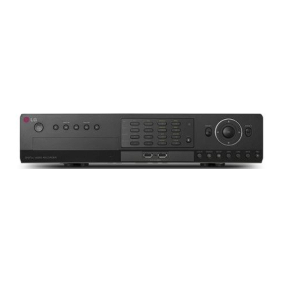
Page 9: Front Panel
Preparation Front Panel Front of the LRD5160 series e f g FOCUS+ IRIS+ INFO ALM.OFF FOCUS - IRIS - TEXT OFF CLEAR 10/0 COPY MARK MOVE TOUR LOGIN SEARCH SETUP VIEW BACK FOCUS+ IRIS+ INFO ALM.OFF FOCUS - IRIS -... - Page 10 Preparation Channel Buttons: You can input a number with channel buttons. You can also use the channel buttons for sub-function with SHIFT button (11 to 16 buttons of 8 channel DVR are used for sub-function without SHIFT button.). • The LED in the button indicates the status as follows: Off: The current status is for live mode.
-
Page 11: Rear Panel
Preparation VIDEO INPUT 100 - 240 V ~ 50 / 60 Hz LOOP Rear Panel Rear of the LRD5160 series VIDEO INPUT 100 - 240 V ~ 50 / 60 Hz LOOP Rear of the LRD5080 series VIDEO INPUT 100 - 240 V ~ 50 / 60 Hz LOOP VIDEO INPUT: Connect the camera’s video output to these BNC connectors. -
Page 12: Remote Control
Preparation Remote Control Button Description POWER (1) Turns DVR on or off. LOGIN Displays the User Log-In dialog box or logs out. Set the appropriate DVR system ID to operate via the IR Remote Controller when using the multiple DVR. Press the ID button then press the number button within 2 seconds to select the system ID of the DVR. -
Page 13: Installation
Installation Installation Connections Precautions • Depending on the camera and other equipment there are various ways to connect the unit. Please refer to the camera manual or manuals for other devices as necessary for additional connection information. • Be sure to switch off the camera before installation and connection. Basic Connection Overview Connect the coaxial-type cameras Connect the Monitor, DVR, VCR, or others. -
Page 14: Connecting Camera
Installation Connecting Camera Connecting Display device Connect the video output of your camera to the unit, using a This unit can be output simultaneously from the HDMI, VGA and standard 75 Ω video coaxial cable with BNC connector. SPOT OUT jack. The video signal connection between the DVR and LOOF OUT connector passes the video signal from VIDEO INPUT the monitor. -
Page 15: Connecting Audio Device
100 - 240 V ~ 50 / 60 Hz LOOP Installation VIDEO INPUT HDMI Monitor connection 100 - 240 V ~ 50 / 60 Hz Connect the unit to the HDMI monitor using a HDMI cable (Type A, LOOP High Speed HDMI Cable). -
Page 16: Connecting Atm/Pos
Installation Connecting ATM/POS Connecting Network Connect the ATM/POS unit to the ATM/POS port. You can control and monitor the system via network. With the remote control (monitoring), you can change the system configuration or monitor the image via network. After the ATM/POS device connection installation, check the network settings for the remote control and monitoring work. -
Page 17: Connecting Rs-485 Device
Installation Connecting RS-485 device Connecting LKD1000 controller Connect the LKD1000 controller to control the DVR. (Refer to the This DVR has two data terminals. Use this port to connect PTZ manuals of the LKD1000 controller for more details.) The LKD1000 cameras, DVRs or keypads (optional). - Page 18 Installation VIDEO INPUT Alarm Output 100 - 240 V ~ 50 / 60 Hz Sensor input connection Connect the alarm device to the alarm output. Alarm signal outputs LOOP when an event occur. Alarm output connection VIDEO INPUT 100 - 240 V ~ 50 / 60 Hz LOOP Alarm device Alarm device...
-
Page 19: Hdd Installation
Installation HDD INSTALLATION 7. Connect the SATA cable to the SATA connector on the main board. 8. Assemble the top case. 9. Fix the screws. Note for Hard Disk Drive 10. When you turn the power of the unit on, the new HDD is The internal hard disk drive (HDD) is a fragile piece of equipment. -
Page 20: System Operation
Installation System Operation General Explanation of the Live Screen on the Main Monitor 1. Turn on the unit. System booting will commence. The LG logo image will be displayed on the main monitor during the system Main Monitor Screen booting. -
Page 21: Moving The Channel's Position
Installation Selecting the Main Monitor screen mode Displays the current surveillance live screen. h System Control Bar You can select the live screen mode to display a full, 4-split, 6-split, Displays date and time. 8-split, 9-split, 16-split, 17-split or 25-split screens on the main monitor. -
Page 22: Selecting The Spot Monitor Screen Mode
Installation Selecting the Spot Monitor screen mode NOTE You can select the live screen mode to full, 4-split, 9-split or 16-split screens on the spot monitor. The [Split Mode] changes according to a number of selected 1. Press VIEW or click the icon in the system control bar. -
Page 23: Using The Digital Zoom Function
Installation To Tour The Preset Positions NOTE You can tour all preset positions. You can use some options by clicking the right button of the 1. Press the TOUR button or Click the icon. mouse in PTZ camera control mode. All registered preset positions in the camera will be selected •... -
Page 24: Export The Recorded Data
Do not remove the USB device while the export is in progress, it may cause a malfunction. • AVI LG: To playing AVI LG file, you have to install the LG DVR Codec. If you install the LG Network Client, do not need to •... -
Page 25: Viewing The System Log List
Installation Viewing the System Log List Viewing System Information To view the system log list: To view system information: 1. Press the LOG button or click the icon in the system control 1. Press the INFO button or click the icon in the system control bar. -
Page 26: Configuration Menu
Installation Configuration menu Setting the Menu Using the Front Panel Buttons or Remote Control Buttons Remote Front Panel Description Control The features and options of the DVR are configured through the menu. The operations of this unit can be set via a menu displayed FOCUS+ IRIS+ Use these buttons to select the... -
Page 27: System Settings
Installation System settings TCP/IP v4 Properties • Interface: Select a LAN port you want to use (Ethernet 0). • DHCP: Select this option when a DHCP server is installed on the network to allow IP address assignment. With this setting, the IP address is assigned automatically. -
Page 28: Network
• Host Name: Enter the host name you want to use. 704*576 1, 3 You can not use the “www”, “mail”, “http”, “ftp”, “com”, “lg”, “lge”, “lgddns”, “lgeddns”, “ddns” for host name. • Registered Host: The registered host name appears. -
Page 29: Date/Time
Installation Date/Time Controller • Date: Select the current year, month and day. • IR Remote ID: Select the IR Remote ID for this unit. If you use multi systems set the IR Remote ID for each DVR unit. • Time: Select the current time. •... -
Page 30: Backup
Installation Daily/Weekly backup 7. Click [OK] to restart the DVR. 1. Connect the USB device for backup. NOTE 2. Select WEEKLY or DAILY on the schedule options. • Do not turn the power off during the update process to 3. Select the backup device. prevent the malfunction. -
Page 31: Device Settings
Installation Device settings NOTE • The backup function is not supported on the external USB CD-ROM driver. Camera • Available external device for backup. Device Capacity USB HDD Up to 2 TB. E-SATA HDD Up to 2 TB. • Use the recommended external USB devices for preventing malfunction (See page 76). -
Page 32: Atm/Pos
Installation Storage w/s: Tests the tilt direction. NOTE The supported PTZ camera list is on page 77 for reference. ATM/POS • Overwrite: : Sets whether you use Overwrighting function. • Full Warning: When the HDD has overflowed a warning message is displayed. -
Page 33: Display Settings
Installation Display settings Video Adjustment Adjust the brightness, contrast and color settings of each camera channel. You can see the settings screen from the preview windows. • Channel: Selects the desired channel to adjust. • Brightness: Adjust the brightness value from 0 to 100 for the selected channel. -
Page 34: Record Settings
Installation Record settings 2. Select a recording mode. Normal Schedule Recording A Normal schedule recoding can be activated at preset times, in a repeating pattern on selected weekdays. The DVR can record according to a schedule set by the user. It can also record manually regardless of date and time. -
Page 35: To Set A Recording Schedule For A Special Day (Special Schedule)
Installation 3. Drag and drop with left button of the mouse to set the channel 3. Use w/s/a/d to enter the necessary information for year, and time you want to record. The color of the time block is month and date. You can use the calendar icon to select the changed depending on the selected mode. -
Page 36: Normal
Installation Normal Motion Settings concerning normal recording. Settings concerning motion recording. • Ch: Displays the channel number. • Ch: Displays the channel number. • Resolution: Selects the recording resolution. • Resolution: Selects the recording resolution. • Quality: Selects the recording picture quality. •... -
Page 37: Instant/Panic
Installation Event settings Instant/Panic Settings concerning instant/panic recording. Sensor • CH: Displays the channel number. • Resolution: Selects the recording resolution. • Quality: Selects the recording picture quality • In: Displays the number of the ALARM-IN terminal. • Frame Rate: Selects the frame rate. The frame rate is the number •... -
Page 38: Atm/Pos Data Format
Installation • Relay Output: NOTE 01 to 04: Outputs the alarm (relay) signal via the RELAY-OUT terminal. When the DVR detects text input, it triggers output • You can select the motion detection area by using the mouse. signals on all the associated RELAY-OUT connectors. To select the area: Drag &... -
Page 39: Notification
Installation Notification • Mail Address (1 to 3): Enter the mail address. You can input up to 3 e-mail addresses. Marks up when you want to activate the selected option. If the • Sender: Enter the sender. selected notification option is activated, the device will notify the user about the information of selected option by E-mail. -
Page 40: Snmp
Installation SNMP Output The Simple Network Management Protocol (SNMP) is an application protocol to exchange the management information of network devices. • Relay Off ALARM ACKNOWLEDGE: Use the ALM.OFF button to stop alarm. • SNMP Version: Selects a SNMP version if SNMP is allowed to POST-ALARM TIME: The alarm is stopped after post-alarm access to this device. -
Page 41: Buzzer
Setup, Search/Play, Export, PTZ, Power Off, Instant Record: Set the authority for the selected group. Mark up the option to activate it. • Main Channel/Spot Channel: Selects the channel to allow the operation for the group user. The LG logo is displayed on the covert channel(s). -
Page 42: User
Installation Setup Wizard settings User You can set the user name for the selected User ID. The Setup Wizard appears on the screen when you turn on the unit for the first time or select [Setup Wizard] on the Setup menu. You can set the system name, display language, data, time, network settings, recording schedule and recording mode on the initial setup wizard. -
Page 43: Step 2
Installation Step 2 Step 4 Set date and time. Set recording schedule. • Date: Select the current year, month and day. • Weekday: Sets the recording mode to weekday (Mon-Fri). • Time: Select the current time. • Weekend: Sets the recording mode to weekend (Sat-Sun). •... -
Page 44: Operation
Operation Operation Instant Recording NOTE • External recording devices can be used as copy areas for images recorded on the hard disk. It is impossible to record Images from a camera will be recorded on the built-in hard disk. images on the external recording devices directly. Ensure all the cameras are connected and that time and date have •... -
Page 45: Instant Playback
Operation Instant Playback 7. Press ad (Play) button or click button to start playback. The picture(s) is (are) displayed on the main monitor. 8. Press STOP (Z) to stop playback and return to the search menu. 9. Press BACK repeatedly to exit the [Date/Time] menu. It is possible to play a recorded image without stopping recording. -
Page 46: Bookmark/Protect Search
Operation ATM/POS Search 5. Use w/s/a/d button to select the channel and press OK button to confirm the selection. If you want to select the all Search the recorded text information by ATM/POS device. channels, marks up the [Select All] option. This function is available with backup data of the internal or external 6. -
Page 47: Export Search
Operation Export Search Smart Search Searches an exported data in the external device. Check the export You can be searched the recorded data by specifying the motion device before you proceed. detection conditions. If you want to use this function, you have to connect the external device otherwise the warning message will be displayed. -
Page 48: Functions Available During Playback
Operation Functions Available During Playback Button Function FOCUS+ IRIS+ Playback Remote Control Front panel Control Menu INFO ALM.OFF FOCUS - IRIS - Stops playback. ALARM TEXT OFF CLEAR SHIFT 10/0 INFO ALM.OFF BACK UP COPY MARK MOVE TOUR Pauses playback. ALARM TEXT OFF FOCUS+... -
Page 49: Using The Playback Control Menu
Operation Using the playback control menu Using the Protect function You can use various playback function using playback control menu. This function allows you to protect the recorded data against being automatically overwritten. 1. Play a data recorded. Playback control menu appears at the bottom of the screen. How to select Protect section. -
Page 50: Lg Network Client Program
2. Enter the password. (Note that the default client password are Memory 2 GB or above RAM “000000”.) 3. Click the [OK] button and then the LG Network Client window is Graphics Card 128 MB or above Video RAM (Use latest displayed. -
Page 51: Lg Network Client Overview
LG Network Client Program LG Network Client Overview File End Backup Use to stop and exit the backup Search search function. Selected Menu Tab Software Update Use to upgrade DVR/NVR software or Live window add/upgrade PTZ protocols. Tool Bar Menu Bar 1. - Page 52 When you click the PAUSE button to Information windows. You can add, edit or delete pause the playing the recorded data the site name or group name in LG of the selected channel, the Print Icon Network Client. is activated. You can print the paused...
-
Page 53: Operation And Settings
TCP/IP port number for each DVR/NVR. Register the Site Name or Group Name The first time LG Network Client is started, you should register a site 6. Enter the TCP/IP port number of the DVR/NVR. If it isn’t entered, name to control it by the LG Network Client program. The computer the port number is set by default. -
Page 54: Connect The Group Device
Disconnect: Select to disconnect to the site name. 3. Repeat step 1 to 2 to connect the other site name. NOTE Up to 5 users can connect to the DVR/NVR system using the LG Network Client program. Connect the group device 1. - Page 55 LG Network Client Program Instant playback NOTE It is possible to play a recorded image without stopping recording. 1. Select the [Camera View] tab in the live mode. • To delete the camera from Live Window, Click desired channel number on the [Cameras] and then drag drop where not Live 2.
- Page 56 LG Network Client Program Pan/Tilt/Zoom Tab To Register Preset Positions You can control the PTZ cameras via the network. 1. Move the camera to a point you wish. 1. Select the PTZ camera channel window in the camera view 2. Click the [SET] icon.
-
Page 57: Using The Search Function
LG Network Client Program Log View Tab Edit the favorite 1. Select the registered favorite name and click the right mouse You can see the system log list of selected site name. button. 1. Select the [Log View] tab. 2. Select the [Edit Favorite] option. The Edit Favorite window is 2. - Page 58 LG Network Client Program Event Search Tab Smart Search Tab Searches a recorded picture by date and event type. Searches the recorded data by specifying the motion detection conditions. 1. Select the [Event Search] tab. 1. Select the [Smart Search] tab.
-
Page 59: Using The Remote Setup Function
LG Network Client Program Using the Remote Setup function ATM/POS Search Tab Searches the recorded text information by ATM/POS device. You can set the DVR/NVR configuration of a selected site name This function is available with backup data of the internal or external using this function. - Page 60 LG Network Client Program Device settings obtain the average time among 5 public servers (time.nist.gov, time-a.nist.gov, time-b.nist.gov, ntp.nasa.gov, clock.isc.org). • Private Time Server: Enter the private time server’s IP address or host name. • Sync. Interval: You can set synchronized intervals with the NTP time server to 1 day, 1 hour, 1 month and 1 week.
- Page 61 LG Network Client Program Display settings • O: The verification is valid. • X: The verification is invalid. Check the ID and password again. • XX: Connection failed. 3. Click the [CLOSE] button to exit the window. ATM/POS Setting •...
- Page 62 LG Network Client Program Motion Settings Record settings • Sensitivity: Set the sensitivity level for the created motion detection area. • Relay Output: Select the number of the RELAY-OUT terminal for the output alarm (relay) signal when motion is detected.
- Page 63 LG Network Client Program Event Settings automatically. 3. Select the desired channel to schedule recording. 4. Click the start time cell block and drag & drop to select a time period cell block. Click the start time cell block of a channel and drag & drop across the channels to select the time period block for multi- channel setting at the same time.
- Page 64 LG Network Client Program Notification NOTE Mark up when you want to activate the selected option. If the selected notification option is activate, notify the user about the • ATM/POS Recording Information. information of selected option by E-mail. • Sensor On: Sends an e-mail when a sensor has occurred.
- Page 65 Record: Set the authority for the selected group. Mark up the option to activate it. • Main Channel/Spot Channel: Selects the channel to allow the operation for the group user. The LG logo is displayed on the covert channel(s). User 1. Select the [User ID] from the drop-down list.
-
Page 66: Using The Export Function
AVI LG: To playing AVI LG file, you have to install the LG DVR Codec. If you install the LG Network Client, do not need to install the LG DVR Codec. -
Page 67: Using The E-Map Function
LG Network Client Program Using the E-Map function Add the Map 1. Click the [Add E-Map] button. The Add E-Map window is This function gives a visual overview of the cameras in your displayed. surveillance environment. 2. Click the [...] button in the [E-Map path] option. -
Page 68: Using The Multiple Window Function
LG Network Client Program Using the Multiple Window function Using the Protect function This function allows you to see a live screen maximum 64 channel This function allows you to protect the recorded data against being by using two monitor. -
Page 69: Additional Programs
LG Network Client Program Additional Programs To activate the Emergency Agent program 1. Run the [LG Emergency Agent] program. The Emergency icon is displayed in the system tray. 2. Whenever a notification function occurs, a message box is displayed on the bottom right of the screen. -
Page 70: Export Viewer Program
Playback control buttons. To play the exported data Option setting window. 1. Run the LG Export Viewer program on the PC or in the Export Viewer folder of the external USB device. Progressive bar 2. Select [File] > [Open]. The open window is displayed. -
Page 71: Web Viewer Program
Web Viewer Program You can capture and save the current image in JPEG file format. The initial save folder is “C:\LG Exported Files”. If you want Logging in the Web Viewer to change the storage folder, set the 1. Start the web browser. The recommended browser is Internet [Save Path] option on the WebViewer Explorer with Windows. - Page 72 LG Network Client Program Event Search 1. Select the [Event Search] tab. 2. Click the icon and select starting and ending date. (The selectable date is displayed in blue color.) 3. Enter starting and ending time. 4. Select the camera channel for event search.
-
Page 73: Troubleshooting
Check the power cable on the camera is connected correctly. displayed on the screen but the camera images are not Check there is no problem with the video cable connection between the camera and the LG DVR displayed. system. Turn off the DVR system and turn it on again. - Page 74 Troubleshooting Symptoms Cause & Solution Check the audio recording option is correctly set for the camera you wish to record audio. Audio data recorded with Check the speaker and audio (line input) on the rear of system are connected correctly. video data is not playing.
- Page 75 Troubleshooting Symptoms Cause & Solution E-mail reception failed without SMTP server setting. • Make sure the network is correctly set. • Make sure the mail address is input correctly. • Check the spam mail setting of the input mail address. (If you set the spam mail, some mails are deleted automatically or classified in the spam mail box) •...
-
Page 76: Appendix
Appendix Appendix Recommended Devices Recommended USB Memory list Maker Model Name Capacity LG Electronics XTICK SPIN LG Electronics XTICK UF1 32 G Lexar Jump Drive Memorive TRANSCEND 16 G SKYDRV SANDISK Cruzer 16 G Samsung Electronics SUM-LSB8 Samsung Electronics SUM-PSB... -
Page 77: Supported Ptz Camera List
Appendix Supported PTZ Camera list Pan/Tilt Zoom Protocol Name Maker Focus Iris Preset Tour Setup Speed control LG_MULTIX LG_MULTIX EXTENTION LG_SD168 LG_LS903 LG_ZOOM LPT_A100L PELCO_D PELCO PELCO_P PELCO GANZ_DSCP GANZ_P360V1 GE KALATEL_CYBERDOM KALATEL PANASONIC_CS850 PANASONIC BOSCH_AUTODOME BOSCH SAMSUNG_SCC SAMSUNG SAMSUNG_E SAMSUNG... -
Page 78: Time Zones
Appendix Time zones Timezone Timezone name Timezone Abbreviation Eniwetok, Kwajalein -12:00 Midway Island, Samoa -11:00 Hawaii -10:00 Alaska -09:00 -08:00 Pacific Time (US and Canada); Tajuana -08:00 -07:00 Mountain Time (US and Canada), Chihuahua, La Paz, -07:00 -06:00 Mazatlan, Arizona Central Time (US and Canada), Saskatchewan, Guadalajara, Mexico City, Monterrey, -06:00 -05:00... -
Page 79: Factory Default Configuration Settings
Appendix Factory Default Configuration Settings Factory Default 1st level 2nd level 3rd level Default Value setting System Name NULL Language The option depends on the model. Button Beep Properties Video Format NTSC or PAL Resolution 1024*768 Configuration Import Configuration Export Factory Default Interface Ethernet 0... - Page 80 Appendix Resolution 352x240 (NTSC) / 352x288 (PAL) Network Streaming Quality STANDARD Frame Rate 7.5 (NTSC) / 6 (PAL) Date Current Date Time Current Time Date Format YYYY/MM/DD Time Format 12 HR Date/Time Time Zone The option depends on the model. Daylight Saving Daylight Saving Start JAN, 1st, SUN, 00...
- Page 81 Appendix Camera Name CH 01 to CH 16 Audio 01 to 04, NONE Channel CH 01 Port NONE Control ID Protocol LG_MULTIX Baud Rate 9600 PTZ Test Interface Device NONE Camera CH 01 Device Baud Rate 9600 ATM/POS Data Bits Stop Bits Parity NONE...
- Page 82 Appendix Current day of the week Mode Normal Schedule Channel Copy Day Copy List Item 1 Name NULL Date --/-- Special Schedule Mode Delete Channel Copy Resolution 352x240 (NTSC) / 352x288 (PAL) Normal Quality STANDARD Frame Rate 7.5 (NTSC) / 6 (PAL) Resolution 352x240 (NTSC) / 352x288 (PAL) Quality...
- Page 83 Appendix Sensor Type Sensor Camera 01 to 16 Relay Output NONE Preset NONE Channel CH 01 Sensitivity Motion Relay Output NONE Area All selected Input Channel Transaction Start NULL Transaction End NULL ATM/POS Data Format Delimiter CARRIAGE RETURN Ignore String NULL Time Out 10 MIN...
- Page 84 Appendix Notification Emergency Host Name NULL Port 9002 SNMP Version NONE Port Community String public User NULL Authentication NONE SNMP Password NULL Privacy NONE Password NULL EVENT Trap IP Address NULL Trap Community String NULL Relay Off ALARM ACKNOWLEDGE System Alarm Out NONE Output HDD Fail Alarm Out...
-
Page 85: Recording Time Table (250Gb Hdd)
Appendix Recording Time Table (250GB HDD) Recording Time (Hr) Video (NTSC/PAL) Video + Audio (NTSC/PAL) Resolution Quality (NTSC/PAL) (8 CH, Video) (16 CH,Video) (8 CH, Video+Audio) (16 CH, Video+Audio) NTSC NTSC/PAL NTSC/PAL NTSC/PAL NTSC/PAL 30.0 25.0 699.75 711.50 349.88 355.75 650.89 661.04 325.44... - Page 86 Appendix Recording Time (Hr) Video (NTSC/PAL) Video + Audio (NTSC/PAL) Resolution Quality (NTSC/PAL) (8 CH, Video) (16 CH,Video) (8 CH, Video+Audio) (16 CH, Video+Audio) NTSC NTSC/PAL NTSC/PAL NTSC/PAL NTSC/PAL 30.0 25.0 357.94 356.09 178.97 178.05 344.70 342.99 172.35 171.49 15.0 12.5 564.38 583.56...
- Page 87 Appendix Recording Time (Hr) Video (NTSC/PAL) Video + Audio (NTSC/PAL) Resolution Quality (NTSC/PAL) (8 CH, Video) (16 CH,Video) (8 CH, Video+Audio) (16 CH, Video+Audio) NTSC NTSC/PAL NTSC/PAL NTSC/PAL NTSC/PAL 30.0 25.0 240.47 237.62 120.24 118.81 234.42 231.71 117.21 115.86 15.0 12.5 379.82 388.56...
-
Page 88: Specifications
Appendix Specifications Model LRD5160 Series LRD5080 Series Input Analog Loop Through Video (Main) VGA Output (Main) HDMI (Spot) Composite Input Audio Output Input Output Buzzer Support Support Alarm e-mail Support Support Notification Remote S/W Support Support (Client S/W, VMS) Emergency S/W... - Page 89 Appendix Power Consumption Maximum 80 W (with 4 HDD) Dimension (W x D x H) 430 mm x 430.5 mm x 96 mm Net Weight (without HDD) 6.14 kg 6.06 kg Net Weight (with 4 HDD) 8.6 kg 8.52 kg Operating Temp.
- Page 90 AB28...