Panasonic AG-HPX500P Operating Instructions Manual
Memory card camera recorder
Hide thumbs
Also See for AG-HPX500P:
- Operating instructions manual (140 pages) ,
- Quick manual (16 pages) ,
- Service manual (191 pages)
Table of Contents
Advertisement
Quick Links
DEUTSCH
Für Erlauterungen in Deutsch, konsultieren Sie bitte die mitgelieferte CD-ROM.
FRANÇAIS
Pour des explications on français, veuillez vous reporter au CD-ROM fourni.
ITALIANO
Per le istruzioni in italiano, vedere il CD-ROM in dotazione.
ESPAÑOL
Para la explicacion en español, consulte el CD-ROM uministrado.
Before operating this product, please read the instructions carefully and save this manual for future use.
0000000000-0
Printed in Japan
Operating Instructions
Memory Card Camera Recorder
Model No.
Model No.
AG-HPX500P
AG-HPX500E
ENGLISH
VQT1G18-0
Advertisement
Table of Contents

Related Manuals for Panasonic AG-HPX500P


Summary of Contents for Panasonic AG-HPX500P
-
Page 1: Operating Instructions
Operating Instructions Memory Card Camera Recorder AG-HPX500P Model No. AG-HPX500E Model No. DEUTSCH Für Erlauterungen in Deutsch, konsultieren Sie bitte die mitgelieferte CD-ROM. FRANÇAIS Pour des explications on français, veuillez vous reporter au CD-ROM fourni. ITALIANO Per le istruzioni in italiano, vedere il CD-ROM in dotazione. - Page 2 Read this first! CAUTION: In order to maintain adequate ventilation, do not install or place this unit in a bookcase, built-in cabinet or any other confined space. To prevent risk of electric shock or fire hazard due to overheating, ensure that curtains and any other materials do not obstruct the ventilation.
- Page 3 Read this first! <For USA and Canada> A rechargeable battery that is recyclable powers the product you have purchased. <For USA-California Only> This product contains a CR Coin Cell Lithium Battery which contains Perchlorate Material — special handling may apply. See www.dtsc.ca/gov/hazardouswaste.perchlorate.
-
Page 4: Precautions For Use
(Details are given in the original (English-language) text.) To obtain the source codes, go to the following home page: http://panasonic.biz/sav/. The manufacturer asks users to refrain from directing inquiries concerning the source codes they have obtained and other details to its representatives. -
Page 5: Table Of Contents
Contents Precautions for Use ...................4 Camera Unit Features..................8 Chapter 1 Recording and Playback Features ..............10 Introduction Outline of operations..................12 Flow of shooting, playing and saving ............12 Saving and editing on external devices .............13 System Configuration..................14 Power Supply and Accessory Mounting Section ........15 Chapter 2 Audio (input) Function Section..............16 Parts and their... - Page 6 Setting user bits ..................59 Setting the User Bits ..................59 Setting the Time Code ................61 Externally Locking the Time Code ............63 Outputting the time code externally ............64 CTL Count Setting and Display..............64 GENLOCK and time code input/output connection and setup ....65 Mode Check Screen Displays (MODE CHECK button function)....
- Page 7 Clip Property ....................104 P2 Card Status Display ................104 SD memory card Status Display ..............106 Confirmation of Metadata Upload ............106 Viewfinder and LCD Menus ................107 Chapter 7 Using the menus ..................107 Menu Operations Initializing the menu settings..............108 Setup menu structure..................109 Camera (CAM) mode menu ..............109 MCR mode menu ..................
-
Page 8: Camera Unit Features
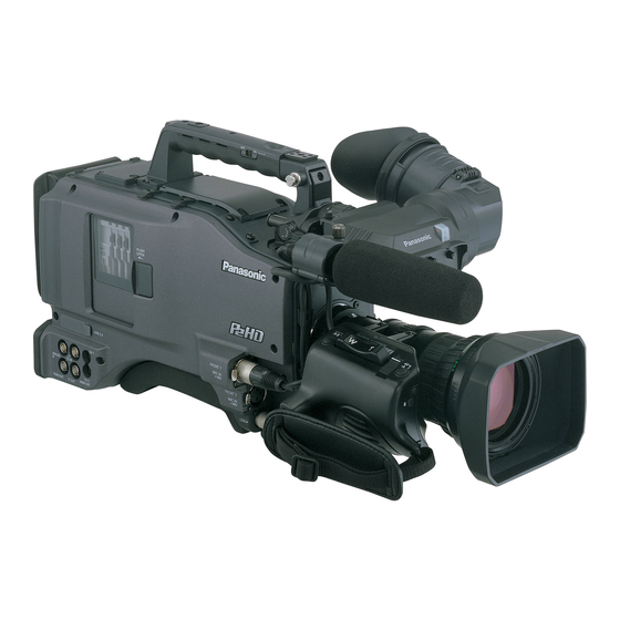
Introduction Chapter The AG-HPX500P/E P2 memory card camera-recorder is equipped with a 2/3-inch lens mount system that enables use of high-performance interchangeable lenses, and comes with a 50 Hz/59.94 Hz selector function to permit use of a multitude of HD and SD formats. - Page 9 * 24p, 30p and 60p/60i indicate recording at 23.98p, 29.97p and 59.94i, respectively. ■Eight gamma curves, including cine-like gamma The DSP provides Panasonic’s proprietary selectable gamma feature. To expand camera capabilities, the camera offers eight gamma modes including cine-like gamma to give the characteristic warm tone of film recordings and a news gamma curve for newsgathering.
-
Page 10: Recording And Playback Features
Recording and Playback Features ■A variety of interfaces The AG-HPX500P/E can record 48 kHz/16-bit uncompressed high-quality digital audio in all formats. The 4-channel audio capability makes both microphone and line input possible on up to four channels. HD-SDI output, time code input and output, GEN lock input and USB 2.0 connector are also provided. - Page 11 ■Clip thumbnail preview The camera records each cut as a clip (file) and automatically attaches a thumbnail image and file information to it. To preview a clip on the LCD monitor or to check clip data, simply choose the clip you want from the list of thumbnails. These thumbnails and the file data can be viewed on a PC (P2 Viewer ) or processed in a nonlinear editing program * “P2 Viewer”...
-
Page 12: Outline Of Operations
Outline of operations This unit is compatible with P2 (Professional Plug-in) cards. Excelling at high transfer speeds, the P2 card enables high vision recording and smooth editing and dubbing. Flow of shooting, playing and saving The setting values such as the user file are saved to and read from the SD memory card. -
Page 13: Saving And Editing On External Devices
Saving and editing on external devices Connecting external devices via the USB connector (Page XX) The data (file) is transferred for nonlinear editing on your computer or other unit. P2 card Computer ® USB2.0 (Windows ® IEEE1394 (SBP-2*) (Macintosh Connecting external devices via the IEEE1394 connector (Page XX) The unit directly controls the external hard disk drive, and transfers the data (file) to it. -
Page 14: System Configuration
Remote Control Unit: AJ-RC10G Remote control cable: Viewfinder: AJ-C10050G AJ-VF15BP/BE AJ-VF20WBP/BE AG-VF11G DIONIC90/160 HYTRON50/100/140 PROPAC14, TRIMPAC14 Lens: (Bayonet type) AG-HPX500P/E Fujinon, Canon ENDURA7/10 V mount type BP-GL65/95 Battery plate NP-L7 NP-1 type Rain cover: Battery mount SHAN-RC700 Soft carrying AC adapter... -
Page 15: Power Supply And Accessory Mounting Section
Power Supply and Accessory Mounting Section POWER switch Tripod mount Used to turn on/off the power. When you want to mount the AG-HPX500P/E Battery mount on a tripod, the optional tripod adapter (SHAN- TM700) is attached here. A battery pack from Anton/Bauer is mounted LENS jack (12-pin) here. -
Page 16: Audio (Input) Function Section
Audio (input) Function Section MIC IN (microphone input) jacks AUDIO LEVEL CH3/CH 4 (audio channel 3 FRONT1/FRONT2 (XLR, 3-pin) & 4 recording level adjustment) controls Connect microphones (optional accessories) to Set the menu option AUTO LEVEL CH3/AUTO these jacks. Power for the microphone comes LEVEL CH4 to OFF in the <AUDIO SETUP>... - Page 17 LINE/MIC/+48V (line input/mic input/mic input + 48V) selector switch Used to select the audio signal input from the AUDIO IN CH1/CH2 connectors. LINE: Audio signal line-input from the audio device is input. MIC: Audio signal from a self-powered (active) microphone is input. (The main unit does not supply power to the remote microphone).
-
Page 18: Audio (Output) Function Section
Audio (output) Function Section MONITOR SELECT (audio channel) CH1/2 / CH3/4 selector switch Use this switch to select the audio channel whose signals are output to the speakers, earphones or AUDIO OUT connector. CH1/2: Signals on Audio Channels 1 and 2 are output. CH3/4: Signals on Audio Channels 3 and 4 are output. -
Page 19: Shooting And Recording/Playback Functions Section
Shooting and Recording/Playback Functions Section Shooting and Recording (camera unit) AUTO W/B (white/black) BAL switch ND FILTER (filter switching) control Automatically adjusts the white balance. Set the WHITE BAL switch on the side to This control adjusts the amount of light entering [A] or [B] and use this switch to adjust the the CCD. - Page 20 OUTPUT/AUTO KNEE selector switch MODE button This switch selects the video signals sent from This button toggles between the CAMERA mode the camera unit to the memory card recorder unit, and MCR mode at each press. viewfinder and video monitor. Holding down this button for 2 seconds or longer in the MCR mode will engage the PC mode.
- Page 21 17 14...
- Page 22 If this button is pressed when playback is paused, insert a card when an adapter is installed.) the beginning of the next clip is located in pause • Use of Panasonic SD memory cards and mini mode (cue-up mode). SD/mini SDHC cards is recommended. Be sure to format such cards in this camera.
- Page 23 BUSY (operation mode display) lamp This lamp indicates the active status of the SD memory card. It stays illuminated when the card is active. <Note> While the lamp is on, do not insert or remove the card. R-SIDE P2 card access LED This LED indicates access status for all four P2 card slots.
-
Page 24: Menu Operation Section
Menu Operation Section MENU button JOG dial button Press this button to display the setting menu and Use this button to go between menu pages and press it again to return to the previous image. to select and set items in open setting menus This button is not available in the thumbnail (camera menu or MCR menu). -
Page 25: Time Code Section
Time Code Section GENLOCK IN connector (BNC) COUNTER (counter display selector) button This connector is used to input a reference signal before the camera unit is gen-locked, or before The LCD monitor and the viewfinder show the the time code is externally locked. counter value, time code, user bit and frame rate TC IN connector (BNC) data depending on how this switch and the TCG... -
Page 26: Warning And Status Display Functions
Warning and Status Display LCD Monitor Functions LCD monitor The LCD monitor displays the video in the Back tally lamp viewfinder. When the BACK TALLY switch is set to [ON], the Alternatively, it can show clips on the P2 card in a lamp behaves in the same way as the front tally thumbnail format. -
Page 27: Viewfinder
Viewfinder Viewfinder (supplied accessory) Front tally lamp During recording or playback, the viewfinder This lamp goes on during recording when displays the video image in monochrome. It also the TALLY switch is set to [ON]. It also blinks displays warnings, messages, zebra patterns, in synchronisation with the REC lamp in the markers (safety zone and center markers), etc. -
Page 28: Setting Date And Time Of Internal Clock
Recording and Playback Chapter Setting Date and Time of Internal Clock The CLOCK SET value is recorded in the contents ■Time zone (clip), and affects the sequence of playback of the Time Time Area Area thumbnails. Before carrying out recording, be sure to difference difference check and set CLOCK SET and TIME ZONE. - Page 29 Turn the JOG dial button to select YEAR, then press the JOG dial. CLOCK SET YEAR 2007 MONTH HOUR PUSH MENU TO RETURN Turn the JOG dial button to set YEAR to 2007, then press the JOG dial button. • A year between 2000 to 2030 can be set. Turn the JOG dial button to select MONTH, then press the JOG dial button.
-
Page 30: P2 Cards
Tilt up the popped-up EJECT button. P2 CARD ACCESS LED Slide lock button Slide-out door Insert a P2 card into the AG-HPX500P/ E. The P2 CARD ACCESS LED for the appropriate slot indicates the status of the P2 card. For how the P2 card status is indicated, see [P2 CARD ACCESS LED and status of P2 cards]. -
Page 31: Removing P2 Cards
• If a P2 card being accessed is removed, the viewfinder displays “TURN POWER OFF” and the AG-HPX500P/E gives a warning using an alarm and the WARNING LED. In addition, all P2 CARD ACCESS LEDs blink rapidly in orange. -
Page 32: To Prevent Accidental Erasure Of P2 Card Content
P2 card is positioned at Write-protected [PROTECT]. Only reading is enabled. The card is not supported by Card not your AG-HPX500P/E. Replace supported the card. Stays off Incorrect The P2 card is not properly format formatted. Reformat the card. -
Page 33: Basic Procedures
Basic Procedures This section describes the basic procedure for shooting and recording. Insert a P2 card and ensure that the P2 Before you embark on a shoot, pre-inspect your CARD ACCESS LED stays on in orange system to ensure that it works properly. For directions on inspecting your memory card or green. -
Page 34: Shooting
When a battery and P2 cards are installed, set the White/Black Balance Adjustment to switches as detailed below, before starting to use your Recording Completion AG-HPX500P/E. For shooting, follow the steps below. Use the ND FILTER control to select a filter according to light conditions. -
Page 35: Normal Recording
To use the electronic shutter, set the shutter speed and shutter mode. For more information, see [Setting the Electronic Shutter]. Press the REC START/STOP button to start recording. • During recording, the REC lamp in the viewfinder stays illuminated. To stop recording, press the REC START/STOP button. -
Page 36: Variable Frame Rate (Vfr) Recording
Variable Frame Rate (VFR) Recording This camera takes full advantage of P2 card You can select any of 11 recording frame rates ranging characteristics by providing frame skipping from 12 frames per second (fps) to 60 fps. (undercranking) recording and high-speed The list of formats that allow recording by the camera- (overcranking) recording without the use of a frame recorder (Page XX) -
Page 37: Standard Recording
• No signals are output from the 1394 terminal during Press the REC START/STOP button. recording or recording standby in the native mode. • Pressing the REC START/STOP button starts • Sound is not recorded. However, sound will be standard recording in the VFR mode, the recorded when the same frame rate is used for both sound is also recorded. - Page 38 Shooting at standard speed for producing commercials and TV programs Production aimed at HDTV and SDTV broadcasts for TV audiences must use the full frame rate (×1) of 30 fps (30 frames/sec.) (25 fps at 50 Hz). Use the following settings to obtain the playback speed used for broadcasts.
-
Page 39: Special Recording Modes
Special Recording Modes During P2 card recording, setting items in the menu Press the START/STOP button. option RECORDING SETUP screen provides the This setting will record audio and video a time following special recording modes: pre-recording, period prior to start of recording. interval recording, one-shot recording, and loop •The following recording modes will disable the recording. -
Page 40: One-Shot Recording (One-Shot Rec)
One-shot recording (ONE- Select INTERVAL in the REC FUNCTION SHOT REC) item in the menu option RECORDING SETUP screen. This function records a single shot at each unit of time which has been set. Set the time in the INTERVAL TIME item in the menu option RECORDING SETUP Check that the OPERATION TYPE item screen. -
Page 41: Loop Recording (Loop Rec)
Loop recording (LOOP REC) Press the START/STOP button. • When two or more P2 cards are inserted in the P2 • Recording starts. card slots, each card is recorded in succession. • Press the START/STOP button to stop • When there is no longer any space left on the cards, recording. -
Page 42: Shot Marker (Shot Mark) Recording Function
Shot Marker (SHOT MARK) Text Memo Recording Recording Function Function This function can be used to distinguish a clip from Text memo allows the user to insert a text memo other clips by adding a thumbnail to each clip. with time code at any point during clip recording and This also makes possible to display or play back the playback. -
Page 43: Normal And Variable Speed Playback
Normal and Variable Speed Playback ■Normal speed playback The PLAY button provides monochrome playback through the viewfinder and colour playback on the LCD monitor. Connecting a color video monitor to the VIDEO OUT connector and SDI OUT connector at the same time will enable viewing of the playback video in color. -
Page 44: Video And Recording Formats
Adjustments and Settings for Recording Chapter Video and recording formats Selecting recording signals Multiple HD/SD formats in CAMERA MODE This unit supports recordings in 20 HD and SD video formats. 1080i/720p HD recording uses the DVCPRO HD codec, while SD recording is performed in CAMERA MODE allows you to record video shot with DVCPRO50/DVCPRO DV multi-codec. -
Page 45: Selecting Mcr Mode Recording And Playback Signals
Selecting MCR mode Selecting video output recording and playback CAMERA MODE and MCR mode allow you to select video output format. signals Use the setting menus listed below to select video output. MCR mode allows you to record signals from the 1394 Setting menu Setting connector and play back P2 card clips. -
Page 46: Camera Mode
List of recording and output formats CAMERA mode ■SYSTEM FREQ (setting menu): 59.94 Hz Format Output Recording status Output status setting setting Capture Audio Recording CMPNT/ COMPONENT VIDEO recording SDI OUT 1394 output FORMAT recording format SDI SEL channels AUDIO frame rate 1080i/ 1080i/... - Page 47 ■SYSTEM FREQ (setting menu): 50 Hz Format Output Recording status Output status setting setting Capture Audio Recording CMPNT/ COMPONENT VIDEO recording SDI OUT 1394 output FORMAT recording format SDI SEL channels AUDIO frame rate 1080i/ 1080i/ 720P 1080i/50i DVCPRO HD 1080i/ 1080i/50i 1080i/...
-
Page 48: List Of Recording, Playback And Output Formats
List of recording, playback and output formats MCR mode (playback and recording of 1394 input) ■SYSTEM FREQ (setting menu): 59.94 Hz Output Format setting Recording status Output status setting Recording Recording and CMPNT/ COMPONENT VIDEO Playback of 1394 playback SDI OUT FORMAT playback format SDI SEL... -
Page 49: Adjusting The White Balance And Black Balance
Adjusting the White balance and Black Balance To record high-quality video with the AG-HPX500P/ Adjust the ND FILTER control according E, the black and white balances must be adjusted to the light conditions. according to conditions. For examples of ND FILTER adjustments, see... -
Page 50: White Balance
Error message Description Remedies The adjustment will take effect in a few Shooting conditions seconds, and the following message may be unstable. AWB was not will appear: If flicker occurs, completed TIME OVER press the shutter • The adjusted value is automatically stored in within the time and readjust the the selected memory (A or B). -
Page 51: Adjusting The Black Balance
• You use your AG-HPX500P/E the first time. appear: • Your AG-HPX500P/E has not been used for some time. • The ambient temperature has changed substantially. • The gain switchover value has been changed. -
Page 52: Setting The Electronic Shutter
Setting the Electronic Shutter Setting the Shutter Mode Follow the steps below. and Speed Shutter Modes The table below shows the shutter modes and speeds Press the SHUTTER switch, positioned for the electronic shutter provided in your AG- HPX500P/E. at [ON], towards [SEL]. Mode Shutter speed Application... -
Page 53: Placing The Camera-Recorder In Synchro Scan Mode
Placing the Camera-recorder Once more, press the SHUTTER switch in SYNCHRO SCAN Mode towards [SEL]. Repeat this switchover until the desired mode or speed appears in the viewfinder screen. To place the camera-recorder in SYNCHRO SCAN • If all modes and speeds are available, the display mode, follow the steps below. -
Page 54: Assigning Functions To User Buttons
Assigning functions to USER buttons The USER MAIN, USER1, and USER2 buttons can be assigned user-selected functions. Use the menu options USER MAIN, USER1, and USER2 to assign functions to respective button. Select these items from the setting menu SW MODE screen. SW MODE MID GAIN HIGH GAIN... -
Page 55: Selecting Audio Input Signals And Adjusting Recording Levels
Selecting Audio Input Signals and Adjusting Recording Levels This AG-HPX500P/E supports independent four- Your AG-HPX500P/E is factory-set to perform no channel audio recording in any format (HD or SD). recording on Audio Channels 3 and 4 in the DVCPRO When the AUDIO SELECT CH1/CH2 switch is and DV formats. -
Page 56: Selecting Function For The F. Audio Level Control
0 dB bar. F : 1 R : 2 When operating the AG-HPX500P/E without a sound recordist, it is recommended that the F. AUDIO LEVEL control should be used to adjust the audio level. -
Page 57: Setting Time Data
Setting Time Data This camera records time data such as the time code, ■Date (real time) user bits, date and time (real time) data in the subcode • The built-in clock calculates the year, month, day and area, VIDEO AUX area and in clip meta data files. time from the internal clock to display on video in the LCD, viewfinder and VIDEO OUT and other video output. -
Page 58: Recording Time Codes And User Bits
Recording time codes and user bits These values are recorded as listed below depending on system frequency and recording format. FRAME Output Subcode MODE. VIDEO AUX Recorded Displayed MODE/ RATE Subcode area time area VIDEO AUX area SYSTEM area time code time code time code (FILM... -
Page 59: Setting User Bits
Setting user bits Setting the User Bits Use the setting menu UB MODE to select the user bits The user bits allow information, including memos that to record in the subcode area. use up to eight-digit hexadecimal numbers (date and •... - Page 60 Press the SET button, check the set user bit value and position the TCG switch at F-RUN or R-RUN. When 1080i, 480i or 576i <Note> Frame rate: 24P over 60i (2:3) Changing the TCG switch setting without First field of updated frame rate pressing the SET button disables the set value.
-
Page 61: Setting The Time Code
Setting the Time Code Time code function during battery replacement Even during battery replacement the backup Switch the menu option TC MODE to DF mechanism keeps the time code generator functioning for a considerable time (about one year). or NDF using the menus. (In 59.94 Hz <Note>... - Page 62 Time code in 720P native mode • At 24PN, recording is performed at 24 frames and output uses a 2:3 pull-down scheme to produce 30 frames. • At a frame rate (capture frame rate) of 24P the speed of recording and the output time code matches actual time, but not at any speed other than 24P.
-
Page 63: Externally Locking The Time Code
Code VIDEO SYNCRO to TC IN, GL SELECT to COMPOSITE and CMPNT/SDI SEL to 720P. The time code generator built into your AG-HPX500P/ To externally lock the time code E may be locked with an external generator. It is also Follow the steps below. -
Page 64: Outputting The Time Code Externally
0. connector gen-lock the camera. <Notes> • To externally lock the AG-HPX500P/E, as the master device, with more than one unit, the mode must be the same as that of the camera. Note that in a system using both interlaced and progressive scanning, there may be breaks in the video and time code. -
Page 65: Genlock And Time Code Input/Output Connection And Setup
Displays (MODE CHECK button function) HPX500P/E TC IN • The viewfinder can display a screen that allows you to check the settings and status of the AG-HPX500P/ GENLOCK HD signal TC OUT • Hold down the DISP/MODE CHECK button in... -
Page 66: Viewfinder Screen Status Displays
This lamp starts blinking a few minutes before status of the AG-HPX500P/E, together with messages, the battery charge starts to run out, and stays a center marker, a safety zone marker and the camera illuminated after the battery is completely flat. -
Page 67: Screen Displays
Screen displays 1 2 : 3 4 : 5 6 : 0 0 2 9 9 9 min P 2 L A C K P A U S E U S E R - 1 1394 C A C HD1080i AWB NG ABB NG P 3 .2 K... -
Page 68: Information Display
Backup unit displays Calendar • The status of the backup unit connected to the 1394 connector is displayed here. Month: • Nothing is displayed if in the setup menus, JAN (January), FEB (February), OTHER FUNCTIONS screen, 1394 CONTROL, MAR (March), APR (April), MAY (May), JUN (June), JUL(July), AUG (August), you have selected “OFF”. - Page 69 Remaining battery charge Displays marker As the remaining battery charge drops, the Markers are displayed when the MARKER item in display changes as follows: the setting menu DISPLAY SETUP screen is set → → → → When the battery has completely discharged, to ON.
-
Page 70: Warnings
<Thumbnail operations> AWB, ABB error indication In a mode check, the status of AWB and ABB that • CANNOT ACCESS do not operate normally is shown. Cannot access clips. • CANNOT DELETE ■Safety zone Cannot delete clips. • CANNOT FORMAT The range of the zone is indicated by the SAFETY Cannot format P2 cards or SD memory cards. -
Page 71: Errors
Errors Camera status display These are displayed when an error occurs in the unit, • ABW: ABW indicator • ABB: ABB indicator P2 card, tape, or other component. If the problem is not fixed by turning the power off and then on again, •... -
Page 72: Checking And Displaying Shooting Status
Checking and displaying Setting the Marker Displays shooting status Turn marker display on or off. Select the display mode from the setting menu DISPLAY SETUP screen. • Hold down the DISP/MODE CHECK button in For directions on navigating the menu, see [Setting recording standby or during recording to display Menu Options]. -
Page 73: Adjusting And Setting The Lcd Monitor
Adjusting and setting the LCD monitor Using the LCD Monitor Use the menu option LCD SET to set display the brightness, color level, and Turn on the POWER switch of the AG- HPX500P/E. contrast of the screen. • Select these items from the setting menu DISPLAY SETUP screen. -
Page 74: Handling Setup Data
Handling setup data Configuration of setup data files This camera makes it possible to save a scene file to each of the F1 to F6 positions on the SCENE FILE dial. Use of an SD memory card makes it possible to save up to four of the F1 to F6 files on an SD card for later retrieval. -
Page 75: Handling Sd Memory Cards
SCENE FILE • Exposed to water droplets; or USER FILE • Electrically charged. SD CARD FORMAT For storage, the SD memory card must be kept inserted into the AG-HPX500P/E with the lid closed. PUSH MENU TO RETURN Handling setup data... -
Page 76: How To Use Scene File Data
■Factory setting The card will not be formatted if the following message appears when the JOG dial button is pressed: • F1: SCENE Error message Remedy File suitable for normal shooting. SD CARD FORMAT NG NO • F2: SCENE FLUO. CARD Insert an SD memory card. - Page 77 ■Example2: Save the F1 scene file to the camera. Turn the JOG dial button to move the cursor to YES. Then, press the JOG dial Turn the JOG dial button to move the button. cursor to the option LOAD/SAVE/INT. SCENE F1 Then, press the JOG dial button.
-
Page 78: Saving Scene Files And Other Settings On Sd Memory Cards
Turn the JOG dial button to move the Select SCENE FILE on the setting menu cursor to YES. Then, press the dial CARD FUNCTIONS screen, select YES, button. and press the JOG dial button. • To return to the menu level above, press the •... - Page 79 To title a file Select YES using the JOG dial button, and press the JOG dial button. • In the following example, TITLE 1 is the Perform steps 1 to 4. filename. • When writing is completed, WRITE OK appears. Use the JOG dial button to select characters, then press the JOG dial SCENE FILE (SD CARD)
-
Page 80: Chapter 5 Power Supply
Preparation Chapter Power Supply Mounting the Battery and A battery pack or AC power can be used as the power supply for the camera-recorder. Setting the Battery Type Using a Battery Pack Battery packs from the following manufacturers can be Using an Anton/Bauer Battery Pack used: •... - Page 81 Using an NP-1 type battery pack When replacing the battery holder, consult your Insert the battery and slide it in the distributor. direction of the arrow. Remove the battery holder. Release lever Battery holder <Note> ●Removing the battery pack Completely push down and hold the release lever on the battery holder.
-
Page 82: Using An Ac Power Supply
Using an AC Power Supply When using a V-mount type battery pack Mount the V-mount adapter plate. Insert the plate and Plug the DC OUT connector into the slide it in the direction of the arrow. camera-recorder’s external DC input socket. - Page 83 <Notes> • When both the battery pack and AC adapter are connected, power is supplied from the AC adapter. The battery can be removed or mounted while using the AC adapter. • When using the AC adapter, make sure you turn ON the AC adapter power before turning ON the camera- recorder’s power switch.
-
Page 84: Mounting The Viewfinder And Adjusting Its Position
Mounting the Viewfinder and Adjusting its Position For more information, refer to the Operating Instructions supplied with the viewfinder. Turn the viewfinder securing screw • Note that old attachment models are not supported. clockwise (to prevent it from falling off). Mounting the Viewfinder Tighten the viewfinder right-left positioning rings. -
Page 85: Adjusting Viewfinder Front-To-Rear Position
Adjusting Viewfinder Front- Screen Adjustments to-Rear Position Use the following controls to adjust viewfinder screen. • Brightness: Turn the BRIGHT control. • Contrast: Turn the CONTRAST control. • Peaking: Turn the PEAKING control. When equipped with slide rail for front-to-rear adjustment Turn on the POWER switch on the camera. -
Page 86: Removing The Viewfinder
Removing the Viewfinder Confirm that the POWER switch is turned off. Loosen the viewfinder right-left positioning rings. Turn the viewfinder securing screw counterclockwise, slide the viewfinder in the direction of the arrow and remove it. Loosen Viewfinder securing screw Disconnect the viewfinder cable and microphone clamp from the clamp and remove them. -
Page 87: Mounting The Lens And Performing The Flange Back Adjustment
Mounting the lens and Performing the Flange Back Adjustment Mounting the Lens Lower the lens clamping lever to clamp the lens. Raise the lens clamping lever and remove the mount cap. Mount Cap Lens Clamping Lever To mount the lens, align the indentation Secure the cable through the cable at the top center of the lens mount with clamp, and plug it into the LENS... -
Page 88: Adjusting The Lens Flange Back
Adjusting the Lens Flange Back If images are not clearly focused at both telephoto and Set the zoom ring to the wide-angle wide-angle positions during zoom operations, adjust position and turn the F.f ring to bring the flange back (distance from the lens mounting the chart into focus. -
Page 89: Preparing For Audio Input
Preparing for Audio Input Take the following steps to prepare the camera for connecting audio input devices. Connect the microphone cable to the MIC IN jack on the camera. When Using the Front Microphone The AJ-MC700P microphone kit (optional) includes a microphone that can be mounted on the camera. -
Page 90: When Using Audio Devices
When Using Audio Devices Connect the audio device to the AUDIO IN jack with the XLR cable. Set the AUDIO IN switch to [REAR] for the channel to which the XLR cable is connected. Set the LINE/MIC/+48V selector switch on the rear panel to [LINE]. LINE/MIC/+48V Selector Switch AUDIO IN Jack AUDIO IN Switch... -
Page 91: Attaching Accessories
Attaching Accessories Mounting the Camera on a Mount the camera on the tripod adapter. Tripod • Slide the camera forward along the grooves until you hear a “click”. When mounting the camera on a tripod, use the tripod adapter supplied with the camera. Mount the tripod adapter on the tripod. -
Page 92: Attaching The Shoulder Strap
Attaching the Shoulder Attaching the F. AUDIO Strap LEVEL Control Knob To detach the shoulder strap, first open the hooks, If you use the F. AUDIO LEVEL control frequently, then detach the strap. attach the accessory knob so that it can be easily operated. -
Page 93: Connecting The Aj-Rc10G Extension Controller
Connecting the AJ-RC10G Extension Controller • Some functions can be remote-controlled when the AJ-RC10G extension control unit (optional) is connected to the camera. • When the AJ-RC10G is connected, the camera automatically enters remote control mode after the power switches of both the camera and the AJ- RC10G are turned ON. -
Page 94: Chapter 6 Thumbnail Operations
Manipulating Clips with Thumbnails Chapter A clip is a data group that includes the images and voices created from one shooting session, together with additional information such as text memos and meta data. The following manipulations can be performed using the cursor and SET buttons, while checking the images displayed on the LCD monitor: ●Play back, delete and repair clips ●Add or delete a shot mark on the clip thumbnail. - Page 95 Thumbnail Screen Recording mode/format display This is where the recording mode and format of Press the MODE button to engage the MCR mode and the recorded images are displayed. open the thumbnail screen on the LCD monitor. When Indicators switching is done from the regular screen display M (Shot mark): to the thumbnail screen display, all the clips will be This indicates that a clip has a shot mark.
-
Page 96: Switching The Thumbnail Display
It is possible to display only the selected thumbnails Move the pointer to THUMBNAIL and in the thumbnail screen for playback. Please refer select with the SET button. to [Switching the Thumbnail Display] for more • The setting sub -menu appears. information. -
Page 97: Setting The Thumbnail Display Mode
Setting the Thumbnail • DATE FORMAT: You can specify the display order for the shooting Display Mode date as either Year/Month/Day (YMD), Month/Day/ Year (MDY) or Day/Month/Year (DMY). The factory setting is Year/Month/ Day. The thumbnail display mode can be customized to suit This setting is reflected in the recording date your preferences. -
Page 98: Clip Operations
Clip Operations Playing Back Clips Pressing the STOP button during clip playback stops the playback and returns the display to the thumbnail Press the MODE button to enter the screen. MCR mode. <Note> When playback is stopped, the position of the •... -
Page 99: Deleting Clips
Restoring Clips <Notes> When adding a shot mark to (or deleting the shot mark from) a clip recorded across multiple P2 cards, do this Restores clips that are defective as a result of sudden with all these P2 cards inserted into P2 card slots. poweringdown during recording, or removal of the P2 card being accessed. -
Page 100: Setting Of Clip Meta Data
P2 viewer from the following URL and install it to your PC: Insert the SD memory card that http://panasonic.biz/sav/p2 contains the Clip Meta Data (metadata upload file). Regarding SD memory cards to be used, see [Cautions in using SD memory cards]. -
Page 101: Recording Method
If clip metadata has been read in COUNT value* <Note> If no clip metadata has been read The AG-HPX500P/E only displays printable ASCII in or if the setting for recording clip Same as CLIP NAME characters. metadata has been turned off * The COUNT value is indicated as a four-digit number. - Page 102 ■Example of recording (DVCPRO50) a clip on one P2 card: REC start (recording start) REC/PAUSE (recording pause) Recording duration = Approx. 15 min. Clip 1 Clip 2 COUNT value COUNT value = 0002 = 0001 5 m i n . 10 min.
-
Page 103: Formatting P2 And Sd Memory Cards
Formatting P2 and SD Memory Cards Formatting SD memory Formatting a P2 Card cards Press the MODE button to enter the SD memory cards can also be formatted from the MCR mode. thumbnail screen. With an SD memory card inserted •... -
Page 104: Properties
Properties P2 Card Status Display The clip’s properties and the P2 card’s status are displayed. P2 Card Status Display Settings Clip Property Select PROPERTY → CARD STATUS to set the desired indication mode (remaining free space or used Select PROPERTY → CLIP PROPERTY. memory capacity) for the P2 card status display. - Page 105 Contents of P2 Card Status Display ■When “USED” is selected: Settings Select PROPERTY → PROPERTY SETUP → P2CARD CAP. The following screen appears. ■When “REMAIN” is selected: Write-protect Mark The mark appears if the P2 card is write- protected. P2 Card Status (used memory capacity) The used memory capacity of the P2 card is Write-protect Mark indicated by a bar graph and a percentage figure.
-
Page 106: Sd Memory Card Status Display
SD memory card Status Confirmation of Metadata Display Upload The status display enables a confirmation of the SD • The contents of the metadata upload file that is read memory card formatted condition, available memory from the SD memory card can be checked. capacity etc. -
Page 107: Chapter 7 Viewfinder And Lcd Menus
Menu Operations Chapter Viewfinder and LCD Menus Using the menus When the unit is in other than playback Use the setup menus to change the settings to suit the or recording mode, press the MENU scenes you are shooting or what you are recording. button. - Page 108 Initializing the menu settings Use the JOG dial button (or the Up and Down cursor buttons) to highlight the The menu settings contain both the user file settings item you want to change. and the scene file settings. You can initialize them separately.
-
Page 109: Setup Menu Structure
Setup menu structure Camera (CAM) mode menu CAMERA MENU SCENE FILE LOAD/SAVE/INIT OPERATION TYPE CAMERA SETUP ASPECT CONV FRAME RATE SETUP SYNCRO SCAN DETAIL LEVEL SW MODE V DETAIL LEVEL MID GAIN HIGH GAIN DETAIL CORING W.BAL.PRESET CHROMA LEVEL USER MAIN CHROMA PHASE USER1 COLOR TEMP Ach... -
Page 110: Mcr Mode Menu
BATTERY SETUP EXT DC IN SEL BATTERY SELECT CARD FUNCTIONS SCENE FILE BATTERY MODE USER FILE PROPAC14 NEAR SD CARD FORMAT TRIMPAC14 NEAR HYTRON50 NEAR HYTRON140 NEAR LENS MODE SHADING SELECT SHADING (USER) DIONIC90 NEAR CAC PROPERTY DIONIC140 NEAR CAC DATA READ NP-L7 NEAR CAC DATA DELETE ENDURA7 NEAR... -
Page 111: Setup Menu List
Setup menu list SCENE FILE screen Item Description of settings (Items in bold are factory settings.) Saves, loads and initializes scene files (SD memory card) LOAD/SAVE/INIT ----(No operation), LOAD (Load), SAVE (Save), INITIAL (Initialize) Switches the shutter and frame rate operation to the video type or film type. ●VIDEO CAM: SYNCRO SCAN is set in 1/n increments. -
Page 112: Camera Setup Screen
Item Description of settings (Items in bold are factory settings.) Selects the gamma curves other than the news gamma curve. ●HD NORM: This gamma setting is suitable for HD shooting. ●LOW: Makes a mellow image using the gamma curve which has a gentle incline in lowbrightness curve. -
Page 113: Sw Mode Screen
SW MODE screen Item Description of settings (Items in bold are factory settings.) Sets the gain value assigned to the M position of the GAIN switch. MID GAIN ●0 dB, 3 dB, 6 dB, 9 dB, 12 dB Sets the gain value assigned to the H position of the GAIN switch. HIGH GAIN ●0 dB, 3 dB, 6 dB, 9 dB, 12 dB Sets the color temperature assigned to the PRST position of the WHITE BAL switch. -
Page 114: Recording Setup Screen
RECORDING SETUP screen Item Description of settings (Items in bold are factory settings.) Selects the recording format for P2 card. ●59.94Hz System: 1080i/60i, 1080i/30P, 1080i/24P, 1080i/24PA, 720P/60P, 720P/30P, 720P/24P, REC FORMAT 720P/30PN, 720P/24PN, 480i/60i, 480i/30P, 480i/24P, 480i/24PA ●50 Hz System: 1080i/50i, 1080i/25P, 720P/50P, 720P/25P, 720P/25PN, 576i/50i, 576i/25P 480i (576i) Selects the 480i (576i) recording mode. -
Page 115: Audio Setup Screen
AUDIO SETUP screen Item Description of settings (Items in bold are factory settings.) Selects the function of the F. AUDIO LEVEL control of CH1 input. ●FRONT: The F. AUDIO LEVEL control controls FRONT1 input. ●REAR: The F. AUDIO LEVEL control controls REAR1 input. FRONT VR CH1 ●ALL: The F. -
Page 116: Outut Sel Screen
OUTUT SEL screen Item Description of settings (Items in bold are factory settings.) Selects D or SDI connector. ●59.94Hz system: 720P, 1080i, 480i CMPNT/SDI SEL ●50 Hz system: 720P, 1080i, 576i Turns on and off metadata superimposition onto the HS-SDI signal. SDI METADATA ●ON, OFF Turns on and off EDH superimposition onto the SD-SDI signal. -
Page 117: Battery Setup Screen
BATTERY SETUP screen Item Description of settings (Items in bold are factory settings.) Selects external DC power supply type. ●AC ADAPTER: AC adapter EXT DC IN SEL ●BATTERY: battery Selects battery type. ●PROPAC14, TRIMPAC14, HYTRON50, HYTRON140, DIONIC90, DIONIC140, NP-L7, ENDURA7, BATTERY SELECT ENDURA10, ENDURA-D, PAG L95, BP-GL65/95, NICD14, TYPE A, TYPE B Near end setting... -
Page 118: Card Functions Screen
CARD FUNCTIONS screen Item Description of settings Reads/writes a scene file from/onto the SD memory card. SCENE FILE ●READ: Loads the selected scene file (F1 to F6) values from an SD memory card. ●WRITE: Saves the current scene file (F1 to F6) settings to the SD memory card. Reads/writes user files (files other than scene files) from/onto the SD memory card. -
Page 119: Other Functions Screen
OTHER FUNCTIONS screen Item Description of settings (Items in bold are factory settings.) Saves users files on, loads users files from the storage area of the camera (EEPROM), and initializes the storage area. ●----: Off (no operation) ●LOAD: Loads the settings in a user file previously stored on the storage area. USER FILE ●SAVE: Saves the user file updated settings on the storage area. -
Page 120: Vf! Led Screen
VF! LED screen Item Description of settings (Items in bold are factory settings.) Sets the conditions (gain value) for lighting the “!” symbol LED in the viewfinder. ●w/o0 dB: other than 0 dB GAIN ●OFF: Off Sets the conditions (white balance value) for lighting the “!” symbol LED in the viewfinder. WHITE ●PRE: Preset ●OFF: Off... -
Page 121: Chapter 8 Connecting To External Devices Using Usb2.0 Port (Pc Mode)
Manual for the details. <Notes> • A USB driver must be installed on the PC. • AG-HPX500P/E is only applicable to USB 2.0, not to USB 1.1. • Only one AG-HPX500P/E at a time must be connected to the PC via USB. -
Page 122: Connecting To External Devices
Connecting to external devices using the IEEE1394 connector (PC mode) Connecting an external PC or hard disk to this unit via IEEE1394 makes it possible to use the P2 cards in this Press the setting menu button to end unit as mass storage. menu operations. -
Page 123: Procedures For Connecting A Hard Disk
• A hard disk is a precision instrument whose read FUNCTIONS screen and set the menu and write functions may fail in some operating environments. Please note that Panasonic accepts no option PC MODE to 1394HOST. liability whatsoever for data loss or other losses either... -
Page 124: Warnings
Warnings • HDD CAPACITY FULL! There is not enough space left on the hard disk. • TOO MANY PARTITIONS! There are too many partitions. • HDD DISCONNECTED! The unit is not connected to a hard disk. • CANNOT INITIALIZE! The hard disk cannot be initialized. •... -
Page 125: Dvcpro Dv Connection Via 1394 Connector
DVCPRO DV Connection via 1394 Connector Recording DVCPRO DV Subcode area time codes and user bits signals input to 1394 • When input from the IEEE1394 interface is selected connector and the TCG switch is set to F-RUN and F-RUN TC SAVE is set to 1394, the time code of the subcode area input from the 1394 connector can be recorded on a P2 card. -
Page 126: P2 Card Recording Times
• Observe the following precautions when controlling the following Web sites. a P2 memory card camera-recorder using PC http://panasonic.biz/sav/ application software (editing software). • Recording cannot be inserted to a portion within a clip. It can only be appended to the end of the newest clip. -
Page 127: Chapter 9 Inspections Before Shooting
Maintenance and Inspections Chapter Inspections Before Shooting Make sure you check that the system is operating normally before embarking on a shoot. We Insert a P2 card into the card slot and recommend using a colour video monitor to check the close the slide cover. -
Page 128: Inspecting The Memory Recording Functions
Inspecting the Memory Inspecting the Camera Unit Recording Functions Set the zoom to electric zoom mode Make sure you successively carry out the inspections and check the zoom operation. from [Inspecting the P2 Card Recording] to [Inspecting • Check that the image changes to telephoto the Earphone and Speaker]. - Page 129 Inspecting the Earphone and Speaker Use the USER button to which the SLOT SEL function has been assigned to select P2 cards for recording when Turn the MONITOR control to check more than one P2 card is inserted in that the speaker volume changes. the card slots.
- Page 130 Inspection of the clock, time code, and user bits Set the user bits as required. Please refer to [Setting the User Bits] for the setting procedures. Set the time code. Please refer to [Setting the Time Code] for the setting procedures. Set the TCG switch to [R-RUN].
-
Page 131: Maintenance
Maintenance Cleaning Inside the Phenomenon Inherent to CCD Viewfinder Cameras Smears • Do not use thinner or other solvents to remove dirt from the viewfinder. • Smears may appear when shooting an object with • Wipe the lens with a commercially available lens very high brightness. -
Page 132: Warning System
Warning System Warning Description Tables If a problem is detected immediately after the power is turned on, or during operation, this will be indicated by the WARNING lamp, lamps inside the viewfinder and a warning tone. LCD or Viewfinder Warning description Warning Tally Warning... - Page 133 LCD or Viewfinder Warning description Warning Tally Warning Alarm Priority viewfinder and recording/ Countermeasures type lamp lamp tone * indication (except tally) playback operation The BATT LED blinks (during The last bar in recording, the the battery level Battery BATT LED Blinks 1 Blinks 1 The battery is near...
-
Page 134: Updating Camera Drivers
Updating Camera Drivers • For the latest information on software drivers, visit the P2 Support Desk at the following Web sites. http://panasonic.biz/sav/ • Before updating the camera driver, check camera driver version in the PROPERTY → SYSTEM INFO in the thumbnail menu. Then access the site listed above to download a driver if necessary. -
Page 135: Chapter 10 Dimensions And Specifications
Specifications Chapter Dimensions and specifications Dimensions 261mm 318mm 140mm Dimensions and specifications... -
Page 136: Specifications
Specifications General Power supply: DC12 V (11 V to 17 V) Power consumption: Approximately 22 W (When 1.5 inch CRT of view finder and 3.5 inch LCD monitor of main unit are ON) Ambient operating temperature/ 0 °C to 40 °C/10% to 85% (no condensation) humidity: Weight: Approximately 3.7 kg (main unit only) - Page 137 Memory Card Recorder Unit Recording format: DVCPRO HD/DVCPRO50/DVCPRO DV selectable Recording audio signal: • PCM digital recording, 48 kHz/16-bits • 4 CH (DVCPRO HD/DVCPRO50), 2 CH/4 CH selectable (DVCPRO DV) Recording/playback time*: • Approx. 8 minutes (When recorded in DVCPRO HD format using one AJ-P2C008HG card with audio signals recorded on 4 channels) •...
- Page 138 Other Input/Output TC IN: BNC × 1, 0.5 V p-p to 8 V p-p, 10 kΩ TC OUT: BNC × 1, low impedance, 2.0 V p-p ± 0.5 V p-p IEEE1394: 6 pins, digital input/output (compliant with IEEE 1394) DC IN: XLR ×...
-
Page 139: Connector Signal Description
L CH OUT (H) L CH OUT (C) +12V R CH OUT (H) R CH OUT (C) Panasonic Part No. K1AA104H0038 Panasonic Part No. K1AA105H0016 Manufacturer Part No. HA16RX-4P (SW1) Manufacturer Part No. HA16RD-5P (Hirose Electric Co.) (Hirose Electric Co.) <Note>... - Page 140 PANASONIC BROADCAST & TELEVISION SYSTEMS COMPANY UNIT COMPANY OF PANASONIC CORPORATION OF NORTH AMERICA Executive Office: One Panasonic Way 4E-7, Secaucus, NJ 07094 (201) 348-7000 EASTERN ZONE: One Panasonic Way 4E-7, Secaucus, NJ 07094 (201) 348-7196 Southeast Region: (201) 348-7162 WESTERN ZONE: 3330 Cahuenga Blvd W., Los Angeles, CA 90068 (323) 436-3500...