Husqvarna Rider 16 Operator's Manual
Husqvarna lawn mower operator's manual
Hide thumbs
Also See for Rider 16:
- Operator's manual (52 pages) ,
- Workshop manual (77 pages) ,
- Workshop manual (74 pages)

Related Manuals for Husqvarna Rider 16


Summary of Contents for Husqvarna Rider 16
- Page 1 Rider 16 Operator´s manual Please read these instructions carefully and make sure you understand them before using the machine. 101 91 33-95...
-
Page 2: Table Of Contents
For servicing other than described in this manual contact an authorised dealer for parts and service. CONTENTS Operator’s Manual for Rider 16 Maintenance ... 20 Maintenance schedule ... 20 Dismantling of the machine hoods ... 21 Checking and adjusting the steering wires ... 22 Adjusting the brake ... -
Page 3: General Operation
SAFETY INSTRUCTIONS These instructions are for your safety. Read them carefully. Safe operation practices for ride-on mowers IMPORTANT! This cutting machine is capable of amputating hands and feet and throwing objects. Failure to ob- serve the following safety instructions could result in serious injury or death. General operation 1. -
Page 4: Safety Instructions
SAFETY INSTRUCTIONS Never allow children to operate the machine. 6. Use extra care when approaching blind cor- ners, shrubs, trees or other objects that may obscure vision. IV. Service 1. Use extra care in handling gasoline and other fuels. They are flammable and vapours are explosive. -
Page 5: Introduction
INSTRUCTION Dear customer Thank you for choosing a Husqvarna Rider. Husqvarna Riders are built to a unique design with a front- mounted cutting unit and a patented rear-wheel steering system. Riders are designed for maximum efficiency even in small or confined areas. The closely grouped controls and pedal-operated hydrostatic transmission also contribute to the performance of this machine. -
Page 6: Serial Number
SAFETY INSTRUCTIONS Good service Husqvarna products are sold all over the world and only through servicing dealers. This is to ensure that you, the customer, get the best support and service. Before the machine is delivered it undergoes inspection and is adjusted by your dealer. -
Page 7: Explanation Of Symbols
EXPLANATION OF SYMBOLS These symbols are on the machine and in the operator’s manual. Study them carefully so that you know what they mean. Reverse Neutral Fast Oil pressure Cutting height Hydrostatic free wheel Use eye and hearing protection Sound- Warning! level Rotating blades. -
Page 8: Safety Instructions
SAFETY INSTRUCTIONS These instructions are for your safety. Read them carefully. This symbol implies that important safety rules are applicable. This is for your safety and the operating reliability of the machine. General use: • Make yourself familiar with the controls and how to stop quickly. -
Page 9: Driving On Slopes
SAFETY INSTRUCTIONS • Watch out for traffic when working close to a road, or crossing one. • Be careful when rounding a fixed object so that the blades do not hit it. Never drive intentionally over a foreign object. • The machine is heavy and can cause very severe crush injuries. -
Page 10: Children
SAFETY INSTRUCTIONS • Do not cut close to edges, ditches or banks. The machine can suddenly tip over if a wheel goes over the edge of a drop or a ditch, or if a bank gives way. • Do not cut wet grass. It is slippery and the tyres can loose their grip so that the machine slides. - Page 11 SAFETY INSTRUCTIONS • Avoid overfilling. f fuel has been spilt on the Rider wipe it up and wait until it has evaporated before starting the engine. If fuel is spilt on clothes, change them. • Be extra careful when handling battery acid. Spilling acid on the skin can cause severe burn injuries.
-
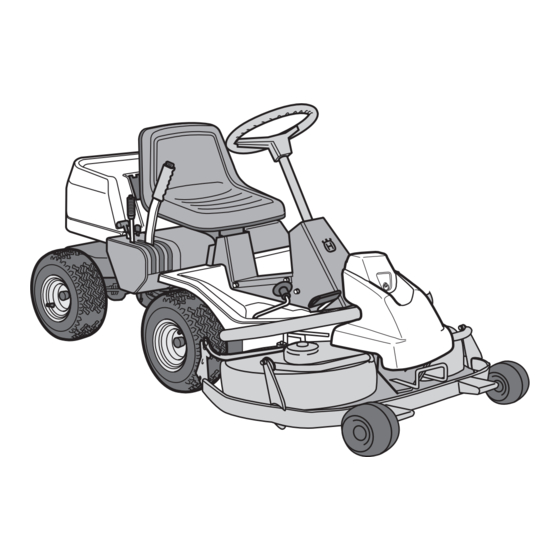
Page 12: Presentation
Presentation Congratulations on your choice of a top quality product which you will enjoy for many years. These instructions describe the Rider 16. This rider mower is equipped with a 15.5 horsepower Briggs & Stratton engine. Location of the controls... -
Page 13: Throttle/Choke Lever
Throttle and Choke lever The engine speed is adjusted with the throttle control, and thereby also the rotation speed of the blades. The control is also used to activate the choke function. When the choke is used the engine receives a richer mixture of fuel and air, which simplifies cold start. -
Page 14: Cutting Unit
Cutting unit The Rider 16 can be fitted with four different cutting units. Rear ejector - 970 mm Side ejector - 970 mm BioClip - 900 mm, 1030 mm Lift lever for cutting unit The lift lever is used to set the cutting unit in trans- port or cutting position. -
Page 15: Lever For Adjustment Of Cutting Height
Lever for adjustment of cutting height With this lever the cutting height can be adjusted to 9 different positions (4-90 mm, 45-80 mm Bioclip). Cutting unit with side/rear ejector, 40-90 mm. BioClip cutting unit, 45-95 mm. Seat The seat has a jointed attachment on the front edge and can be tipped forward. -
Page 16: Driving
• Read the safety instructions and information on the location and function of the controls before starting (see pages 7-14). • Conduct daily maintenance before starting (see maintenance schedule on page 20). Adjust the seat to the required position. Starting the engine 1. - Page 17 Warm engine: 4. Set the throttle control midway between position 1 and 2. 5. Turn the ignition key to start position. IMPORTANT INFORMATION Do not run the starter for more than about 5 seconds at a time. If the engine does not start, wait about 10 seconds before trying again.
-
Page 18: Driving The Machine
Driving the machine 1. Release the parking brake by pressing down the brake pedal. 2. Carefully press down one of the pedals until the correct speed is reached. To drive forwards: press down pedal (1). To reverse: press down pedal (2). 3. -
Page 19: Cutting Tips
4. Push in the lock button on the lift lever and lower down the cutting unit. IMPORTANT INFORMATION The service-life of the drive belts increases considerably if the engine is run at low speed when engaging the blades. For this reason do not increase the throttle until the cutting unit has been lowered to the cutting position. -
Page 20: Stopping The Engine
WARNING! Never drive the machine on ground with a slope of more than 15 . Mow slopes upwards and downwards, never across. Avoid sudden changes in direction. Stopping the engine Preferably allow the engine to idle for a minute to obtain normal working temperature before stopping it if it has been working hard. -
Page 21: Maintenance
The following is a list of the maintenance which should be conducted on the machine. For the items which are not described in these instructions go to an authorised service workshop. Maintenance Check the engine’s oil level Check the engine’s cooling air inlet Check the fuel pump’s air filter Check the steering wires Check the battery... -
Page 22: Dismantling Of The Machine Hoods
Dismantling of the machine hoods Engine hood The engine is accessible for servicing when the engine hood is lifted up. Tilt the seat forward, release the rubber strap under the seat, and tilt the hood backwards. Front hood Release the clip on the front hood and lift off the fender. -
Page 23: Checking And Adjusting The Steering Wires
Checking and adjustment of the steering wires The steering is controlled by means of wires. These can in time become slack, which implies that the adjustment of the steering becomes altered. Check and adjust the steering as follows: 1. Dismantle the frame-plate by releasing the screws (two on each side). -
Page 24: Checking And Adjustment Of Throttle Wire
Checking and adjustment of the throttle wire If the engine does not respond as it should do when the throttle lever is moved or if the top speed is not reached, the throttle wire may need adjusting. 1. Loosen the clamping screw (by the arrow), and slide the throttle to the choke position. -
Page 25: Replacement Of Air Filter
Replacing the air filter If the engine seems to lack power or goes irregularly the reason may be that the air filter is clogged. It is therefore important to replace the air filter at regular intervals (see maintenance schedule on page 20 for correct service interval). -
Page 26: Checking The Fuel Pump's Air Filter
Checking of the fuel pump’s air filter Check regularly that the fuel pump’s air filter is free from dirt. The filter can when necessary be cleaned with a brush. Check the level of the battery acid Check that the level of the battery acid lies between the markings. -
Page 27: Checking The Safety System
Inspecting the safety system The Rider is equipped with a safety system that prevents starting or driving under the following conditions: The engine should only be possible to start when the cutting unit is in its raised position and the hydrostat pedals are in the neutral position. -
Page 28: Checking The Tyre Pressure
Checking the tyre pressure The tyre pressure should be 60 kPa (0.6 kp/cm round. To improve driving the pressure on the rear tyres can be reduced to 40 kPa (0.4 kp/cm2). The maximum tyre pressure is 100 kPa (1.0 kp/cm IMPORTANT INFORMATION Different tyre pressures on the front tyres will result in the blades cutting the grass... -
Page 29: Fitting The Cutting Unit
Fitting the cutting unit 1. Position the Rider on a flat surface and apply the parking brake, see page 12. Check that the lever for adjusting the cutting height is at the lowest setting. Make sure the support wheels are fitted to the cutting unit (1). -
Page 30: Checking And Adjustment Of Cutting Unit's Ground Pressure
Checking and adjustment of the cutting unit’s ground pressure To achieve the best cutting results the cutting unit should follow the underlying surface without pres- sing too hard against it. The pressure is adjusted with a screw on each side of the machine. -
Page 31: Adjusting The Parallelism Of The Cutting Unit
Adjusting the parallelism of the cutting unit 1. Remove the front hood and right-hand fender, as described on page 21. 2. Undo the nuts on the lift strut. 3. Unscrew the strut (anticlockwise) to lower the rear edge of the hood. Screw the strut in (clockwise) to raise the rear edge of the hood. -
Page 32: Replacing The Cutting Unit Belts
Replacing the cutting unit belts Replacing the belts on a BioClip unit A BioClip unit is driven by two toothed belts that synchronise the rotation of the blades. The belts sit underneath a cover on the cutting unit. 1. Dismantling the cutting unit, see page 30. 2. - Page 33 IMPORTANT IMFORMATION On a BioClip unit the blades are set at an angle of 90 to each other. If this angle changes, the blades may touch and cause damage to the cutting unit. 5. Fitting: First slide on the lower belt, then the upper belt.
-
Page 34: Service Position For Cutting Unit
Service position for cutting unit The cutting head can be placed in the service position to provide easy access for cleaning, repairs and servicing. In the service position the cutting unit is raised and locked in the vertical position. Placing in service position 1. - Page 35 4. Fit the support wheels on either side of the rear of the cutting unit. WARNING! Wear protective glasses when dismantling the cutting unit. The spring which tensions up the belt can go off and cause personal injury. 5. Disengage the spring from the drive belt tensioning wheel.
- Page 36 8. Lift off the drive belt (1). Then pull out the pin (2). Take care not to get your hand trapped. 9. Pull the frame forwards and refit the pin. 10.Grasp the front edge of the cutting unit, pull out and raise into the service position.
-
Page 37: Checking The Blades
Checking the blades To achieve the best mowing results it is important that the blades are undamaged and well-sharpened. Check that the blades’ attachment screws are tight. IMPORTANT INFORMATION Replacing or sharpening the blades should be conducted by an authorised service workshop. -
Page 38: Replacing The Break-Pin (Bioclip)
Replacing the break-pin (BioClip) The blades are fitted with a break-pin to protect the BioClip unit and its drive when colliding with obstacles. A domed, spring friction washer is fitted to each blade bolt. The washer must always be replaced with a new washer if the blade bolt is loosened. -
Page 39: Lubrication
Check the engine’s oil level Check the oil level in the engine when the machine is horizontal. Fold open the engine cover as described on page Release the dip stick and pull out. Wipe off the oil and insert again. The dip stick must be fully screwed down. -
Page 40: Checking The Transmission's Oil Level
Check the transmission’s oil level 1. Remove the transmission cover. Loosen both screws (one on each side) and lift off the trans- mission cover. 2. Check that there is oil in the transmission’s oil tank. Fill if necessary with engine oil SAE 10W/ 30 (class SF–CC). -
Page 41: Trouble Shooting Schedule
TROUBLE SHOOTING SCHEDULE Problem Engine will not start. Starter does not pull round engine. Engine does not run smoothly. Engine seems to have no power. Engine overheats. Battery does not charge. Machine vibrates. Uneven mowing. – English Procedure • Fuel tank empty. •... -
Page 42: Storage
Winter storage At the end of the season the machine should immediately be put in order for storage, also if it is going to stand idle for more than 30 days. Fuel which is left to stand for long periods (30 days or more) can leave tacky deposits which can block the carburettor and interfere with the engine. -
Page 43: Technical Data
Note that no legal claims are valid on the basis of information in this manual. Use only genuine parts for repairs. The warranty is not valid if non genuine parts are used. – English TECHNICAL DATA Rider 16 2145 mm 1050 mm 1060 mm... - Page 44 We, Husqvarna AB, S-561 82 Huskvarna, Sweden, tel. +46 36-146500, declare under sole responsibility that the rider mowers Husqvarna Rider 16 from 1998’s serial numbers and onwards (the year is clearly stated in plain text on the type plate with subsequent serial number), is in conformity with the following standards or other normative documents following the provisions in the COUNCIL’S DIRECTIVES:...
- Page 45 SERVICEJOURNAL RIDER 16 Work done Pre-delivery service 1. Top up battery with acid and recharge for four hours. 2. Fit steering wheel, seat and any optional equipment. 3. Adjust cutting unit: Adjust the lifting springs (the “weight” of the cutting unit should be 12-15 kg).
- Page 46 SERVICEJOURNAL Date, mileage, stamp, sign Work done English –...
- Page 47 SERVICEJOURNAL Date, mileage, stamp, sign Work done – English...
- Page 48 SERVICEJOURNAL Date, mileage, stamp, sign Work done English –...
- Page 49 SERVICEJOURNAL Date, mileage, stamp, sign Work done – English ´*3-G¶5O¨...
- Page 50 English –...
- Page 51 ´*3-G¶5O¨ 2001W03...