Lenovo ThinkServer TS140 User Manual
Machine types: 70a0, 70a1, 70a4, and 70a5
Hide thumbs
Also See for ThinkServer TS140:
- User manual (126 pages) ,
- Quick reference manual (14 pages) ,
- Hardware maintenance manual (132 pages)
Table of Contents
Advertisement
Advertisement
Table of Contents
Troubleshooting

Related Manuals for Lenovo ThinkServer TS140

Summary of Contents for Lenovo ThinkServer TS140
- Page 1 ThinkServer TS140 User Guide Machine Types: 70A0, 70A1, 70A4, and 70A5...
- Page 2 • Appendix A “Notices” on page 93 First Edition (September 2013) © Copyright Lenovo 2013. LIMITED AND RESTRICTED RIGHTS NOTICE: If data or software is delivered pursuant a General Services Administration “GSA” contract, use, reproduction, or disclosure is subject to restrictions set forth in Contract No. GS-35F-05925.
-
Page 3: Table Of Contents
....Updating the server configuration ..Installing security features ..© Copyright Lenovo 2013... - Page 4 ThinkServer Web site ..Electronic emission notices..Lenovo Support Web site..Federal Communications Commission (FCC) Statement.
-
Page 5: Safety Information
제품을 사용하기 전에 제품과 함께 제공되는 문서 DVD의 다국어 안전 지침을 주의 깊게 읽어보십시오. Voordat u het product gebruikt, moet u ervoor zorgen dat u de meertalige veiligheidsinstructies op de documentatie-dvd van het product hebt gelezen en begrijpt. © Copyright Lenovo 2013... - Page 6 Ensure that you read and understand all caution and danger statements in this document before you perform the procedures. Read and understand any additional safety information that is included with the server or optional device before you install, remove, or replace the device. ThinkServer TS140 User Guide...
- Page 7 The battery contains lithium and can explode if not properly used, handled, or disposed of. Do not: • Throw or immerse into water • Heat to more than 100°C (212°F) • Repair or disassemble Dispose of the battery as required by local ordinances or regulations. © Copyright Lenovo 2013...
- Page 8 The device also might have more than one power cord. To remove all electrical current from the device, ensure that all power cords are disconnected from the power source. ThinkServer TS140 User Guide...
- Page 9 Statement 9 CAUTION: Disconnect the hot-swap fan cables before removing the fan from the device to protect against personal injury. Statement 10 CAUTION: The following label indicates a sharp-edge hazard. © Copyright Lenovo 2013...
- Page 10 In addition, the device might have multiple connections to dc power. To remove all electrical current from the device, ensure that all connections to dc power are disconnected at the dc power input terminals. viii ThinkServer TS140 User Guide...
- Page 11 This product contains a Class 1M laser. Do not view directly with optical instruments. Statement 18 CAUTION: Do not place any object on top of rack-mounted products. Statement 19 CAUTION: Hazardous moving parts. Keep fingers and other body parts away. © Copyright Lenovo 2013...
- Page 12 Statement 20 CAUTION: A lithium ion battery is provided. To avoid possible explosion, do not burn the battery. Replace the battery only with the Lenovo-approved part. Recycle or discard the battery as instructed by local regulations. ThinkServer TS140 User Guide...
-
Page 13: Chapter 1. General Information
The Lenovo Limited Warranty (LLW) contains the warranty terms that apply to the product you purchased from Lenovo. Read the LLW on the documentation DVD that comes with your server. A printable generic version of the latest LLW also is available in more than 30 languages at http://www.lenovo.com/warranty/llw_02. -
Page 14: Server Documentation
When you register your server, information is entered into a database, which enables Lenovo to contact you in case of a recall or other severe problem. After you register your server with Lenovo, you will receive quicker service when you call Lenovo for help. In addition, some locations offer extended privileges and services to registered users. - Page 15 This document provides information about component locations, replacement procedures for major Field Replaceable Units (FRUs), and troubleshooting and diagnostics. This document is updated frequently, and the most up-to-date version is always available in English on the Lenovo Web site at: http://www.lenovo.com/ThinkServerUserGuides...
- Page 16 ThinkServer TS140 User Guide...
-
Page 17: Chapter 2. Server Setup Road Map
ThinkServer EasyStartup program. 9. Check for firmware and driver updates. See “Updating the firmware” on page 34. 10. Install other applications. Refer to the documentation that comes with the applications that you want to install. © Copyright Lenovo 2013... - Page 18 ThinkServer TS140 User Guide...
-
Page 19: Chapter 3. Product Overview
Your server comes with one of the following microprocessors (internal cache size varies by model type): ® • Intel Core™ i3 microprocessor ® • Intel Pentium microprocessor ® • Intel Xeon microprocessor For a list of the ThinkServer microprocessor options, go to: http://www.lenovo.com/thinkserver © Copyright Lenovo 2013... - Page 20 • Two USB 2.0 connectors on the rear panel For the location information about the connectors, refer to the related topics in “Locations” on page 11. Video subsystem Integrated graphics for a VGA connector and two DisplayPort connectors ThinkServer TS140 User Guide...
- Page 21 Ethernet connectivity One RJ-45 Ethernet connector on the rear panel with 100 Mbps or 1000 Mbps network connectivity. For more information, see “Rear view of the server” on page 13. Reliability, availability, and serviceability Reliability, availability, and serviceability (hereinafter referred to as RAS) are three important server design features.
-
Page 22: Specifications
(bootable) ThinkServer EasyStartup DVD. The user guide for the program also is on the DVD and can be accessed directly from the program interface. For detailed information, see “Using the ThinkServer EasyStartup program” on page 28. ThinkServer TS140 User Guide... -
Page 23: Thinkserver Easyupdate Firmware Updater
34. BIOS update utilities The BIOS firmware keeps updating after the shipment of the server. Lenovo maintains pages on the Support Web site and provides the BIOS update utilities with instructions for download to help you update the BIOS firmware if needed. -
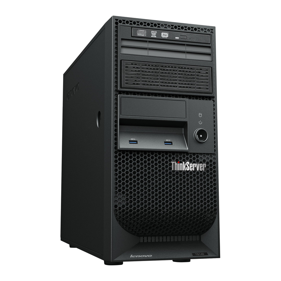
Page 24: Front View Of The Server
The following is a sample of the machine type, model, and serial number label. Figure 2. Machine type, model, and serial number label Front view of the server This topic provides information to help you locate the parts on the front of the server. ThinkServer TS140 User Guide... -
Page 25: Rear View Of The Server
The following illustration shows the front view of the server. Figure 3. Front view of the server Optical drive eject/close button Power button Hard disk drive activity LED USB 3.0 connectors (2) Power-on LED Rear view of the server This topic provides information to help you locate the connectors and components on the rear of your server. Figure 4 “Rear connector locations”... - Page 26 Used to attach a microphone to your server when you want to record sound or if you use speech-recognition software. Serial connector Used to attach an external modem, a serial printer, or other devices that use a 9-pin serial connector. ThinkServer TS140 User Guide...
-
Page 27: Locating Parts On The System Board
Connector Description USB connector Used to attach a device that requires a USB connector, such as a USB keyboard, a USB mouse, a USB scanner, or a USB printer. If you have more than eight USB devices, you can purchase a USB hub, which you can use to connect additional USB devices. -
Page 28: Internal Components
Internal drives are devices that your server uses to read and store data. You can add drives to your server to increase storage capacity and enable your server to read other types of media. Internal drives are installed in bays. ThinkServer TS140 User Guide... - Page 29 Figure 7 “Drive bay locations” on page 17 shows the locations of the drive bays. Figure 7. Drive bay locations Optical drive bay Secondary optical drive bay Card reader drive bay Secondary SATA hard disk drive bay Primary SATA hard disk drive bay (with a 3.5-inch SATA hard disk drive installed) Chapter 3 Product overview...
- Page 30 ThinkServer TS140 User Guide...
-
Page 31: Chapter 4. Turning On And Turning Off The Server
• You can press the power button to start an orderly shutdown of the operating system and turn off the server, if your operating system supports this feature. • If the operating system stops functioning, you can press and hold the power button for more than four seconds to turn off the server. © Copyright Lenovo 2013... - Page 32 ThinkServer TS140 User Guide...
-
Page 33: Chapter 5. Configuring The Server
• On the Devices menu, select ATA Drive Setup and follow the instructions on the screen to view information about the installed SATA or SAS devices, such as a hard disk drive or an optical drive. © Copyright Lenovo 2013... -
Page 34: Setup Utility Program Interface
“Exit menu” on page 24 Lenovo provides the BIOS update utility on the Lenovo Support Web site. You can download the BIOS update utility to update the BIOS if the newer BIOS version specifically solves a problem you have. See “Updating or recovering the BIOS”... - Page 35 • Video Setup: View and set the primary video adapter type. • Audio Setup: Enable or disable the onboard audio controller. • Network Setup: Enable or disable the onboard Ethernet controller and other network features. Advanced menu You can view or change various server component settings on the Advanced menu in the Setup Utility program.
-
Page 36: Setting The System Date And Time
3. Use the Tab key to switch between data elements and type the numbers from the keyboard to set the system date and time. 4. Press F10 to save settings and exit the Setup Utility program. ThinkServer TS140 User Guide... -
Page 37: Using Passwords
Using passwords By using the Setup Utility program, you can set passwords to prevent unauthorized access to your computer and data. The following types of passwords are available: • Power-On Password • Administrator Password You do not have to set any passwords to use your computer. However, using passwords improves computing security. -
Page 38: Configuring The Tpm Function
3. In the boot device selection window, use the up and down arrow keys on the keyboard to switch between the selections. Press Enter to select the device of your choice. Then, the server will start up from the selected device. ThinkServer TS140 User Guide... -
Page 39: Exiting From The Setup Utility Program
Setup Utility program to view or change the configuration settings of your server. See “Using the Setup Utility program” on page 21. Lenovo might make changes and enhancements to the BIOS. When updates are released, they are available for download on the Lenovo Web site at http://www.lenovo.com/drivers. -
Page 40: Using The Thinkserver Easystartup Program
BIOS version. To update (flash) the BIOS, do the following: 1. Go to http://www.lenovo.com/drivers and follow the instructions on the Web page to locate the BIOS update package. 2. Download the BIOS update package and the installation instructions in a TXT file. -
Page 41: Features Of The Thinkserver Easystartup Program
If you do not have a ThinkServer EasyStartup DVD, you can download an ISO image from the Lenovo Support Web site and make a disc by yourself. To download the ThinkServer EasyStartup program image and burn it into a disc, do the following: 1. - Page 42 Agreement. Read the Lenovo License Agreement carefully. In order to continue, you must accept the terms by clicking Agree. Then, the Date and time window opens. 4. Set the current date and time and click OK. The Start option window opens.
-
Page 43: Using The Thinkserver Easystartup Program On A Windows Operating System
DVD into an internal or external optical drive. The DVD starts automatically in most environments. If the DVD does not start automatically, open the launch.exe file located in the root directory of the DVD. Notes: • You should read and accept the Lenovo License Agreement when prompted. ® • On the Microsoft Windows Server... -
Page 44: Configuring The System Bios To Enable Onboard Sata Raid Functionality
1. Start the Setup Utility program. See “Starting the Setup Utility program” on page 21. 2. Select Devices ➙ ATA Drive Setup. 3. Select Configure SATA as and press Enter. 4. Select RAID Mode and press Enter. ThinkServer TS140 User Guide... -
Page 45: Creating Raid Volumes
5. Press F10 to save changes and exit the Setup Utility program. Creating RAID volumes This section describes how to use the Intel Rapid Storage Technology enterprise option ROM configuration utility to create RAID volumes. To create RAID volumes, do the following: 1. -
Page 46: Updating The Firmware
The firmware in the server is periodically updated and the latest firmware is always available for downloading from the Lenovo Web site. Go to http://www.lenovo.com/drivers and follow the instructions on the Web page to check for the latest level of firmware, such as the BIOS updates and device drivers. -
Page 47: Copyright Lenovo
• Before using the product, be sure to read and understand the multilingual safety instructions and the Lenovo Limited Warranty (LLW) on the documentation DVD that comes with the product. Reading and understanding the safety instructions reduces the risk of personal injury and damage to your product. -
Page 48: Handling Static-Sensitive Devices
(ESD) wrist strap, if one is available. Ensure that you work in an ESD-safe area. Select a grounding system, such as those listed below, to provide protection that meets the specific service requirement. Note: The use of a grounding system to guard against ESD damage is desirable but not necessary. ThinkServer TS140 User Guide... -
Page 49: System Reliability Guidelines
– Attach the ESD ground clip to any frame ground, ground braid, or green-wire ground. – When working on a double-insulated or battery-operated system, use an ESD common ground or reference point. You can use coax or connector-outside shells on these systems. –... -
Page 50: Removing And Reinstalling The Front Bezel
Attention: Do not open your server or attempt any repair before reading and understanding “Safety information” on page iii and “Guidelines” on page 35. This section provides instructions on how to remove and reinstall the front bezel. To remove and reinstall the front bezel, do the following: ThinkServer TS140 User Guide... - Page 51 1. Remove all media from the drives and turn off all attached devices and the server. Then, disconnect all power cords from electrical outlets and disconnect all cables that are connected to the server. 2. Remove the server cover. See “Removing the server cover” on page 37. 3.
-
Page 52: Installing, Removing, Or Replacing Hardware
Notes: • Use only parts provided by Lenovo. • Depending on the model, your server might look slightly different from the illustrations in this topic. The EMI integrity and cooling of the server are protected by having all drive bays and PCI Express card slots covered or occupied. -
Page 53: Installing Or Removing The Ethernet Card
Installing or removing the Ethernet card Attention: Do not open your server or attempt any repair before reading and understanding “Safety information” on page iii and “Guidelines” on page 35. This section provides instructions on how to install or remove the Ethernet card. Use any documentation that came with the Ethernet card and follow those instructions in addition to the instructions in this section. - Page 54 For more information about the memory modules in your specific server model, use the Setup Utility program. See “Viewing information in the Setup Utility program” on page 21. For a list of supported ThinkServer memory module options, go to: http://www.lenovo.com/thinkserver The following illustration helps you to locate the memory slots on the system board.
-
Page 55: Installing A Memory Module
Installing a memory module Attention: Do not open your server or attempt any repair before reading and understanding “Safety information” on page iii and “Guidelines” on page 35. This topic provides instructions on how to install a memory module. Before you begin, print all the related instructions or ensure that you can view the PDF version on another computer for reference. -
Page 56: Removing A Memory Module
4. Locate the memory slots on the system board. See “Locating parts on the system board” on page 15. 5. Remove any parts or disconnect any cables that might prevent your access to the memory slots. ThinkServer TS140 User Guide... -
Page 57: Installing Or Removing The Tertiary Hard Disk Drive
6. Locate the appropriate memory module that you want to remove and open the retaining clips on both ends of the memory slot. Then, grasp the memory module by its edges and carefully pull it straight up to remove it from the memory slot. Figure 14. - Page 58 5. Install the retainer on the side of the bracket. Figure 16. Installing the retainer on the side of the bracket 6. If there is a metal static shield installed in the secondary optical drive bay, remove the metal static shield. ThinkServer TS140 User Guide...
- Page 59 7. Slide the drive conversion bracket into the secondary optical drive bay from the front of the server until the bracket snaps into position. Figure 17. Installing the drive conversion bracket into the secondary optical drive bay 8. Connect the signal cable and the power cable to the rear of the new hard disk drive. Figure 18.
- Page 60 4. Disconnect the signal cable and the power cable from the rear of the tertiary hard disk drive. 5. Disconnect the cable of the fan for the tertiary hard disk drive from the fan power converter cable. ThinkServer TS140 User Guide...
- Page 61 6. Press the release button and slide the drive conversion bracket with the tertiary hard disk drive out of the front of the server. Figure 20. Removing the drive conversion bracket 7. Remove the four screws that secure the hard disk drive. Then, remove the hard disk drive out of the drive conversion bracket.
-
Page 62: Installing Or Removing The Slim Optical Drive And The Fourth Hard Disk Drive
4. Install the slim optical drive conversion board into the cage for the slim optical drive and the fourth hard disk drive. Then, install the two screws to secure the slim optical drive conversion board. Figure 22. Installing the slim optical drive conversion board ThinkServer TS140 User Guide... - Page 63 5. Install the two screws to secure the slim optical drive retainer to the side of the slim optical drive. Figure 23. Installing the slim optical drive retainer 6. Install the slim optical drive with the retainer into the cage. Figure 24.
- Page 64 9. Install the four screws to secure the hard disk drive in the cage. Figure 27. Installing the screws to secure the hard disk drive in the cage 10. Install the cage retainer on the side of the cage. Figure 28. Installing the cage retainer ThinkServer TS140 User Guide...
- Page 65 11. Slide the cage with the slim optical drive and the hard disk drive into the optical drive bay from the front of the server until the cage snaps into position. Figure 29. Sliding the cage into the optical drive bay 12.
- Page 66 Figure 31. Removing the cage with the slim optical drive and the fourth hard disk drive ThinkServer TS140 User Guide...
- Page 67 7. Press the release button to eject the tab that secures the slim optical drive. Then, slide the slim optical drive out of the front of the cage. Figure 32. Removing the slim optical drive from the cage 8. Remove the slim optical drive retainer by removing the two screws that secure the retainer. Figure 33.
-
Page 68: Installing Or Replacing A Pci Card
1. Remove all media from the drives and turn off all attached devices and the server. Then, disconnect all power cords from electrical outlets and disconnect all cables that are connected to the server. 2. Remove the server cover. See “Removing the server cover” on page 37. ThinkServer TS140 User Guide... - Page 69 3. At the rear of the server, press the release button to open the PCI card latch Figure 35. Opening the PCI card latch Chapter 6 Installing, removing, or replacing hardware...
- Page 70 6. Install the new PCI card into the appropriate slot on the system board. See “Locating parts on the system board” on page 15. Note: If you are installing a PCI Express x16 card, make sure the memory slot retaining clips are closed before you install the PCI Express x16 card. ThinkServer TS140 User Guide...
- Page 71 7. Pivot the PCI card latch to the closed position to secure the PCI card. Figure 38. Installing a PCI card Note: If you are installing a PCI card into a slot with the retaining clip, close the card retaining clip as shown.
-
Page 72: Installing Or Replacing The Optical Drive
• If you are replacing an optical drive, disconnect the signal cable and the power cable from the rear of the optical drive, press the blue release button and then slide the optical drive out of the front of the server. Figure 40. Removing the optical drive ThinkServer TS140 User Guide... -
Page 73: Installing Or Replacing The Secondary Hard Disk Drive
5. Slide the new optical drive with the optical drive retainer installed into the drive bay from the front of the server until the optical drive snaps into position. Figure 41. Installing the optical drive 6. Reinstall the front bezel. See “Removing and reinstalling the front bezel” on page 38. 7. - Page 74 7. To install the secondary hard disk drive, flex the sides of the bracket properly and align pin , pin , pin , and pin on the bracket with the corresponding holes in the hard disk drive. Do not touch the circuit board on the bottom of the hard disk drive. ThinkServer TS140 User Guide...
- Page 75 Figure 44. Installing the hard disk drive into the bracket 8. Slide the new hard disk drive into the hard disk drive cage until it snaps into position. Figure 45. Installing the secondary hard disk drive Chapter 6 Installing, removing, or replacing hardware...
-
Page 76: Replacing The Primary Hard Disk Drive
2. Remove the server cover. See “Removing the server cover” on page 37. 3. Locate the primary hard disk drive. See “Locating parts on the system board” on page 15. 4. Disconnect the signal cable and the power cable from the rear of the hard disk drive. ThinkServer TS140 User Guide... - Page 77 5. Pull the blue handle to release and remove the hard disk drive from the drive cage. Figure 47. Removing the primary hard disk drive 6. Flex the sides of the blue bracket to remove the hard disk drive from the bracket. 7.
-
Page 78: Replacing The Power Supply Assembly
This section provides instructions on how to replace the power supply assembly. Although there are no moving parts in your server after the power cord has been disconnected, the following warnings are required for your safety and proper Underwriters Laboratories (UL) certification. ThinkServer TS140 User Guide... - Page 79 DANGER Hazardous moving parts. Keep fingers and other body parts away. CAUTION: Never remove the cover on a power supply or any part that has the following label attached. Hazardous voltage, current, and energy levels are present inside any component that has this label attached.
- Page 80 8. Install and tighten the four screws to secure the power supply assembly. Note: Use only screws provided by Lenovo. 9. Reconnect the power supply assembly cables to the system board and each of the drives.
-
Page 81: Replacing The Heat Sink And Fan Assembly
What to do next: • To work with another piece of hardware, go to the appropriate section. • To complete the replacement, go to “Completing the parts replacement” on page 79. Replacing the heat sink and fan assembly Attention: Do not open your server or attempt any repair before reading and understanding “Safety information” on page iii and “Guidelines”... - Page 82 10. Connect the heat sink and fan assembly cable to the microprocessor fan connector on the system board. See “Locating parts on the system board” on page 15. What to do next: • To work with another piece of hardware, go to the appropriate section. ThinkServer TS140 User Guide...
-
Page 83: Replacing The Front Audio And Usb Assembly
• To complete the replacement, go to “Completing the parts replacement” on page 79. Replacing the front audio and USB assembly Attention: Do not open your server or attempt any repair before reading and understanding “Safety information” on page iii and “Guidelines” on page 35. This section provides instructions on how to replace the front audio and USB assembly. -
Page 84: Replacing The Front Fan Assembly
Note: The new front fan assembly will have four new rubber mounts attached. Figure 55. Removing the front fan assembly 6. Install the new front fan assembly by aligning the new rubber mounts with the corresponding holes in the chassis and push the rubber mounts through the holes. ThinkServer TS140 User Guide... -
Page 85: Replacing The Rear Fan Assembly
7. Carefully pull on the tips of the rubber mounts until the front fan assembly is secured in place. Figure 56. Installing the front fan assembly 8. Connect the new front fan assembly cable to the power fan connector on the system board. See “Locating parts on the system board”... - Page 86 Note: The new rear fan assembly will have four new rubber mounts attached. Figure 57. Removing the rear fan assembly 6. Install the new rear fan assembly by aligning the new rubber mounts with the corresponding holes in the chassis and push the rubber mounts through the holes. ThinkServer TS140 User Guide...
-
Page 87: Replacing The Microprocessor
7. Carefully pull on the tips of the rubber mounts until the new rear fan assembly is secured in place. Figure 58. Installing the rear fan assembly 8. Connect the new rear fan assembly cable to the system fan connector on the system board. See “Locating parts on the system board”... - Page 88 6. Lift the small handle and open the retainer to access the microprocessor Figure 59. Accessing the microprocessor 7. Lift the microprocessor straight up and out of the microprocessor socket. Figure 60. Removing the microprocessor ThinkServer TS140 User Guide...
- Page 89 Notes: a. Your microprocessor and socket might look different from the one illustrated. b. Note the orientation of the microprocessor in the socket. You can either look for the small triangle on one corner of the microprocessor or note the orientation of the notches on the microprocessor.
-
Page 90: Replacing The System Board Battery
1. Remove all media from the drives and turn off all attached devices and the server. Then, disconnect all power cords from electrical outlets and disconnect all cables that are connected to the server. ThinkServer TS140 User Guide... -
Page 91: Completing The Parts Replacement
2. Remove the server cover. See “Removing the server cover” on page 37. 3. Locate the system board battery. See “Locations” on page 11. 4. Remove the old system board battery. Figure 62. Removing the old system board battery 5. Install the new system board battery. Figure 63. -
Page 92: Connecting The Cables
Setup Utility program. Refer to Chapter 5 “Configuring the server” on page 21. Note: In most areas of the world, Lenovo requires the return of the defective Customer Replaceable Unit (CRU). Information about this will come with the CRU or will come a few days after the CRU arrives. -
Page 93: Connecting External Devices
Note: If you are attaching an external device, see the documentation that comes with the device for information about cabling. 1. Read and understand the Safety, Warranty, and Support Information at http://www.lenovo.com/support, and “Guidelines” on page 35. 2. Turn off the server and all attached devices. - Page 94 ThinkServer TS140 User Guide...
-
Page 95: Chapter 7. Troubleshooting And Diagnostics
• ThinkServer System Profile Collection Tool To use a diagnostic program, do the following: 1. Go to http://www.lenovo.com/drivers and follow the instructions on the Web page to locate a diagnostic program. 2. Download and unzip the diagnostic program package to get the diagnostic program package folder. -
Page 96: Basic Troubleshooting Tables
See Chapter 8 “Getting information, help, and service” on page 89. Notes: 1. If you are instructed to remove, install, or replace any CRUs, refer to the related procedure in “Installing, removing, or replacing hardware” on page 40. ThinkServer TS140 User Guide... -
Page 97: Hard Disk Drive Problems
2. If an action step is preceded by “(Trained service technician only),” this action step is reserved for a trained service technician and must be performed only by a trained service technician. Action Symptom The optical drive is not recognized. 1. -
Page 98: Memory Module Problems
See “Features” on page • You follow the memory module installation rules. See “Memory module installation rules” on page • All memory modules are seated correctly and securely. • The system firmware is up-to-date. ThinkServer TS140 User Guide... -
Page 99: Keyboard, Mouse, Or Usb Device Problems
Symptom Action 2. If you have any diagnostic programs, run the diagnostic programs to test the memory modules. 3. Reinstall the memory modules. 4. Replace the suspect memory modules. 5. (Trained service technician only) Replace the system board. Keyboard, mouse, or USB device problems Follow the suggested actions for the corresponding symptom in the order in which they are listed until the problem is solved. - Page 100 Symptom Action 2. Restart the server. 3. Replace the USB device. ThinkServer TS140 User Guide...
-
Page 101: Chapter 8. Getting Information, Help, And Service
Using the documentation Information about your Lenovo system and installed software, if any, or optional devices is available in the documentation that comes with the product. The documentation can include printed documents, online documents, readme files, and help files. Most of the documentation for your server is on the documentation DVD provided with your server. -
Page 102: Help And Service
• Check the power switches to ensure that the system and optional devices are turned on. • Use the troubleshooting information in your system documentation on the documentation DVD that comes with your product. • Check for the updated information, new device drivers, and hints and tips on the Lenovo Support Web site at: http://www.lenovo.com/support •... -
Page 103: Using Other Services
Service availability and service names might vary by country or region. For more information about these services, go to the Lenovo Web site at: http://www.lenovo.com... - Page 104 ThinkServer TS140 User Guide...
-
Page 105: Appendix A. Notices
Lenovo representative for information on the products and services currently available in your area. Any reference to a Lenovo product, program, or service is not intended to state or imply that only that Lenovo product, program, or service may be used. Any functionally equivalent product, program, or service that does not infringe any Lenovo intellectual property right may be used instead. -
Page 106: Trademarks
Trademarks Lenovo, the Lenovo logo, and ThinkServer are trademarks of Lenovo in the United States, other countries, or both. Intel, Intel Core, Intel Xeon, and Pentium are trademarks of Intel Corporation in the United States, other countries, or both. Internet Explorer, Microsoft, Windows, and Windows Server are trademarks of the Microsoft group of companies. -
Page 107: Polyvinyl Chloride (Pvc) Cable And Cord Notice
Lenovo encourages owners of information technology (IT) equipment to responsibly recycle their equipment when it is no longer needed. Lenovo offers a variety of programs and services to assist equipment owners in recycling their IT products. For information on recycling Lenovo products, go to: http://www.lenovo.com/recycling... -
Page 108: Battery Recycling Information For Taiwan
The following statement applies to users in the state of California, U.S.A. California Perchlorate Information: Products containing CR (manganese dioxide) lithium coin cell batteries may contain perchlorate. Perchlorate Material - special handling may apply, See http://www.dtsc.ca.gov/hazardouswaste/perchlorate ThinkServer TS140 User Guide... -
Page 109: Important Weee Information
Important WEEE information The WEEE marking on Lenovo products applies to countries with WEEE and e-waste regulations (for example, European Directive 2002/96/EC, India E-Waste Management & Handling Rules, 2011). Appliances are labeled in accordance with local regulations concerning waste electrical and electronic equipment (WEEE). -
Page 110: China Rohs
China RoHS Turkish RoHS The Lenovo product meets the requirements of the Republic of Turkey Directive on the Restriction of the Use of Certain Hazardous Substances in Electrical and Electronic Equipment (EEE). ThinkServer TS140 User Guide... -
Page 111: India Rohs
RoHS compliant as per E-Waste (Management & Handling) Rules, 2011. European Union RoHS Lenovo products sold in the European Union, on or after 3 January 2013 meet the requirements of Directive 2011/65/EU on the restriction of the use of certain hazardous substances in electrical and electronic equipment (“RoHS recast”... - Page 112 This product is in conformity with the protection requirements of EU Council Directive 2004/108/EC on the approximation of the laws of the Member States relating to electromagnetic compatibility. Lenovo cannot accept responsibility for any failure to satisfy the protection requirements resulting from a non-recommended modification of the product, including the installation of option cards from other manufacturers.
- Page 113 Geräte der Klasse A. Dieses Gerät ist berechtigt, in Übereinstimmung mit dem Deutschen EMVG das EG-Konformitätszeichen - CE - zu führen. Verantwortlich für die Konformitätserklärung nach Paragraf 5 des EMVG ist die Lenovo (Deutschland) GmbH, Gropiusplatz 10, D-70563 Stuttgart. Informationen in Hinsicht EMVG Paragraf 4 Abs. (1) 4: Das Gerät erfüllt die Schutzanforderungen nach EN 55024 und EN 55022 Klasse A.
-
Page 114: Eurasian Compliance Mark
For more information about ENERGY STAR, go to: http://www.energystar.gov Lenovo encourages you to make efficient use of energy an integral part of your day-to-day operations. To help in this endeavor, set the following power-management features to take effect when your servers have been used: •... -
Page 115: Index
Setup Utility program getting service devices, handling static-sensitive diagnostic program troubleshooting and diagnostics Diagnostic programs software hard disk drive, replacing diagnostics, troubleshooting heat sink and fan assembly, replacing DIMM help installation rules and service installing help, getting © Copyright Lenovo 2013... - Page 116 Security menu padlock loop Setup Utility program particulate contamination serial number label parts replacement, completing locations password serial port ThinkServer TS140 User Guide...
- Page 117 Setup Utility program system time setting Web site compatible options the BIOS working inside the server with the power on flashing guidelines updating updating or recovering ThinkServer EasyStartup software ThinkServer EasyStartup program © Copyright Lenovo 2013...
- Page 118 ThinkServer TS140 User Guide...