Advertisement
Quick Links
Mounting Instructions
Mounting location
Wiring diagrams
Application
No function
DIP
switches
Siemens Smart Infrastructure
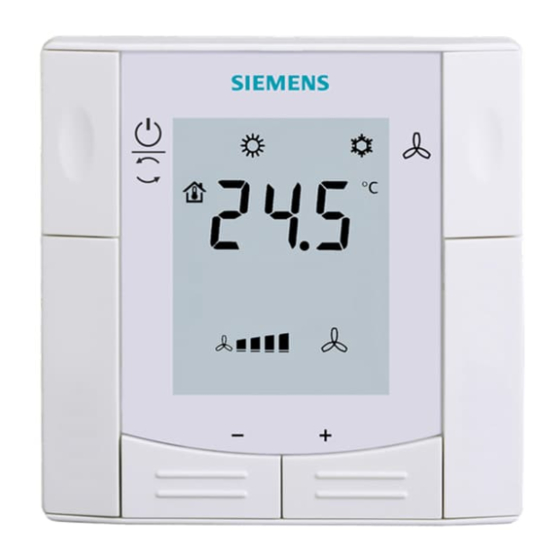
Flush-mounted room thermostat
with RS485 Modbus
communications
Installation video
Datasheet
Factory setting
RDF660MB
X1
3 = Window contact (DI)
X2
1 = External temperature sensor (AI)
RDF660MB/MM
B1
9 = H/C changeover (DI)
S1
3 = Window contact (DI)
Key
N1
RDF660MB/MM, RDF660MB
M1
ECM fan
V1, V2
Valve
C1, C2
Compressor
S2
Operating mode switch-over
contact (e.g. key card)
B2
External room / return air
temperature sensor
E1
Electrical heater
A6V12060783_en--_c
Dimensions (mm)
Mounting
Carefully read all wiring diagrams
prior to installation to avoid
damage to the device caused by
incorrect wiring of high or low
voltages.
Dismounting
A5W00123793A_AC
RDF660MB..
2022-11-24
1/2
Advertisement

Summary of Contents for Siemens RDF660MB Series
- Page 1 Wiring diagrams Application Dismounting RDF660MB/MM, RDF660MB ECM fan V1, V2 Valve C1, C2 Compressor Operating mode switch-over contact (e.g. key card) External room / return air temperature sensor Electrical heater No function switches Siemens Smart Infrastructure A6V12060783_en--_c A5W00123793A_AC 2022-11-24...
- Page 2 All temperature settings are in increments of 0.5 °C. *** Parameter P13 is only displayed for application "2-pipe with electric heater". Issued by © Siemens Switzerland Ltd, 2020 Siemens Switzerland Ltd Technical specifications and availability subject to change without notice.


