Table of Contents
Advertisement
Quick Links
Thank you for purchasing this Panasonic product.
■ The Operating Instructions correspond to the firmware's main version 2.00 and higher.
■ Before operating this product, please read the instructions carefully and save this manual
for future use.
■ Before using this product, be sure to read "Read this first!" ( x pages 5 to 11).
Operating Instructions
DLP™ Projector
Model No.
Functional Manual
Commercial Use
PT-FRZ120C
PT-FRZ120CL
ENGLISH
DPQP1241ZG/X1
Advertisement
Table of Contents

Related Manuals for Panasonic DPL PT-FRZ120C


Summary of Contents for Panasonic DPL PT-FRZ120C
- Page 1 PT-FRZ120C Model No. PT-FRZ120CL Thank you for purchasing this Panasonic product. ■ The Operating Instructions correspond to the firmware’s main version 2.00 and higher. ■ Before operating this product, please read the instructions carefully and save this manual for future use.
-
Page 2: Table Of Contents
Contents Contents Read this first! Chapter 3 Basic Operations Switching on/off the projector Chapter 1 Preparation Connecting the power cord Power indicator Precautions for use Switching on the projector Intended use of the product When the initial setting screen is displayed Cautions when transporting Making adjustments and selections Cautions when installing... - Page 3 Contents [POSITION] menu [PROJECTOR SETUP] menu [SHIFT] [PROJECTOR ID] [ASPECT] [PROJECTION METHOD] [ZOOM] [LENS] [CLOCK PHASE] [OPERATION SETTING] [GEOMETRY] [LIGHT OUTPUT] [ADVANCED MENU] menu [BRIGHTNESS CONTROL] [STANDBY MODE] [DIGITAL CINEMA REALITY] [BLANKING] [QUICK STARTUP] [NO SIGNAL SHUT-OFF] [INPUT RESOLUTION] [NO SIGNAL LIGHTS-OUT] [CLAMP POSITION] [INITIAL STARTUP] [EDGE BLENDING]...
- Page 4 Contents Chapter 5 Operations Network connection Connecting to the network Web control function Computer that can be used for setting Accessing from the web browser Chapter 6 Maintenance Light source/temperature indicators When an indicator lights up Maintenance Before maintaining the projector Maintenance Troubleshooting [SELF TEST] indications...
-
Page 5: Read This First
Read this first! Read this first! WARNING: THIS APPARATUS MUST BE EARTHED. WARNING: To prevent damage which may result in fire or shock hazard, do not expose this appliance to rain or moisture. WARNING: 1. Remove the plug from the mains socket when this unit is not in use for a prolonged period of time. 2. - Page 6 Read this first! WARNING: Do not look at the light emitted from the lens while the projector is being used. As with any bright source, do not stare into the direct beam. Indicated on the projector Notice on laser This projector is the Class 3R laser product that complies with GB 7247.1-2012. GB7247.1-2012 激光辐射...
- Page 7 Read this first! WARNING: r POWER The wall outlet or the circuit breaker shall be installed near the equipment and shall be easily accessible when problems occur. If the following problems occur, cut off the power supply immediately. Continued use of the projector in these conditions will result in fire or electric shock, or will cause visual impairment.
- Page 8 If liquid enters inside of the projector, consult your dealer. f Particular attention must be paid to children. Use the ceiling mount bracket specified by Panasonic Connect Co., Ltd. Using the ceiling mount bracket other than the specified one will result in falling accidents.
- Page 9 Read this first! CAUTION: r POWER When disconnecting the power cord, be sure to hold the power plug and power connector. If the power cord itself is pulled, the lead will become damaged, and fire, short-circuits or serious electric shocks will result.
- Page 10 Read this first! CAUTION: r ACCESSORIES When not using the projector for an extended period of time, remove the batteries from the remote control. Failure to observe this will cause the batteries to leak, overheat, catch fire or explode, which may result in fire or contamination of surrounding area.
- Page 11 Read this first! China Energy Label China energy label is available for this projector. The projection efficiency and passive standby power are indicated on the label in compliance with the standard GB 32028-2015. The energy efficiency of the standard zoom lens supplied model PT-FRZ120C is measured with the standard zoom lens (TKGF0156-5) attached.
- Page 12 “Operating Instructions – Basic Guide” is supplied with the product. At least three (3) years from delivery of this product, Panasonic Connect Co., Ltd. will give to any third party who contacts us at the contact information provided below, for a charge no more than our cost of physically performing source code distribution, a complete machine-readable copy of the corresponding source code covered under GPL V2.0, LGPL V2.1 or the other licenses with the obligation to do so, as well as the respective copyright notice...
- Page 13 Features of the Projector Quick Steps For details, refer to the corresponding pages. 1. Set up the projector. High luminance and high contrast (x page 29) w With a unique optical system which uses a new-generation laser light source, and 2.
-
Page 14: Chapter 1 Preparation
Preparation Chapter 1 This chapter describes things you need to know or check before using the projector. 14 - ENGLISH... -
Page 15: Precautions For Use
Chapter 1 Preparation — Precautions for use Precautions for use Intended use of the product The purpose of the projector is to project a video signal from imaging equipment or a computer on a screen or other surface as a still image or moving image. Cautions when transporting f If you purchased the projector with the standard zoom lens, remove the lens protection material before use, and store it for the future use. - Page 16 Chapter 1 Preparation — Precautions for use rAsk a qualified technician or your dealer for the installation work such as installing to a ceiling, etc. To ensure projector performance and safety, ask a qualified technician or your dealer when installing to a ceiling or in a high place.
- Page 17 Chapter 1 Preparation — Precautions for use rCautions when setting up the projector f The projector can be used by installing its top placed on the floor. To prevent the top surface from getting scratched during use, it is recommended to attach about a 20 mm (25/32") square buffer material (such as rubber cushion) on the four corners of the top surface.
-
Page 18: Security
Change your password periodically. A password can be set in the [SECURITY] menu → [SECURITY PASSWORD CHANGE]. f Panasonic Connect Co., Ltd. or its affiliate companies will never ask for your password directly. Do not divulge your password in case you receive such inquiries. -
Page 19: Digital Link
(https://panasonic.net/cns/projector/). Note that the verification for devices of other manufacturers has been made for the items set by Panasonic Connect Co., Ltd., and not all the operations have been verified. For operation or performance problems caused by the devices of other manufacturers, contact the respective manufacturers. -
Page 20: Cautions On Use
Chapter 1 Preparation — Precautions for use Cautions on use rTo get a good picture quality In order to view a beautiful image in higher contrast, prepare an appropriate environment. Draw curtains or blinds over windows and turn off any lights near the screen to prevent outside light or light from indoor lamps from shining onto the screen. -
Page 21: Accessories
Chapter 1 Preparation — Precautions for use Accessories Make sure that the following accessories are provided with your projector. Numbers enclosed in < > show the number of accessories. Wireless/wired remote control unit <1> Lens Mount Cover <1> (N2QAYA000061) (1GE1RZ970BU) Lens cover <1> (TKKL5244-1) Power cord <1>... -
Page 22: About Your Projector
Chapter 1 Preparation — About your projector About your projector Remote control Front Bottom Power standby <v> button Number (<0> - <9>) buttons Sets the projector to the state where the projector is turned off Used for entering an ID number or a password in a multiple (standby mode) when the <主电源>... - Page 23 Chapter 1 Preparation — About your projector g Be sure the batteries are inserted properly. For other instructions, read the instructions related to batteries that are described in “Read this first!”. Caution label at the back of the remote control Note f When operating the remote control by directly pointing at the remote control signal receiver of the projector, operate the remote control within a distance approximately 30 m (98'5") from the remote control signal receiver.
-
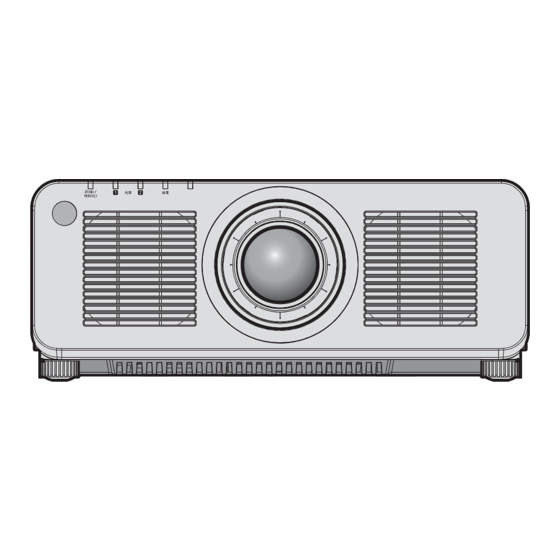
Page 24: Projector Body
Chapter 1 Preparation — About your projector Projector body Front Side Rear Light source indicator <光源1> Bottom Indicates the status of light source 1. Light source indicator <光源2> Indicates the status of light source 2. Temperature indicator <温度> Indicates the internal temperature status. (Not used with this projector) Adjustable feet Adjusts the projection angle. - Page 25 Chapter 1 Preparation — About your projector r Control panel Power on <b> button <菜单> button Sets the projector to projection mode when the <主电源> switch Displays or hides the main menu. (x page 71) on the projector is set to <开> and the power is turned off Returns to the previous menu when a sub-menu is displayed.
- Page 26 Chapter 1 Preparation — About your projector r Connecting terminals <REMOTE 1 输入> terminal/<REMOTE 1 输出> terminal <SDI 输入> terminal These are terminals to connect the remote control for serial This is a terminal to input the SDI signal. control in a multiple projector environment. <RGB 1 输入>...
-
Page 27: Preparing The Remote Control
Chapter 1 Preparation — Preparing the remote control Preparing the remote control Inserting and removing the batteries (ii) Fig. 1 Fig. 2 Open the cover. (Fig. 1) Insert the batteries and close the cover (insert the m side first). (Fig. 2) f When removing the batteries, perform the steps in reverse order. -
Page 28: Chapter 2 Getting Started
Getting Started Chapter 2 This chapter describes things you need to do before using the projector such as the setup and connections. 28 - ENGLISH... -
Page 29: Setting Up
Chapter 2 Getting Started — Setting up Setting up Usable outlet A grounded outlet supporting 220 V/15 A is required when using the projector. Following illustration is an example of the shape of the usable outlet. 2P/3W 15 A 250 V Attention f Use the supplied power cord and ground at the outlet. - Page 30 Chapter 2 Getting Started — Setting up Portrait setting and projecting forward Portrait setting and projecting from rear (Using the translucent screen) Menu item Setting value Menu item Setting value [FRONT/REAR] [FRONT] [FRONT/REAR] [REAR] Set in accordance with the image Set in accordance with the image [FLOOR/CEILING] [FLOOR/CEILING] to project.
-
Page 31: Parts For Installation (Optional)
Chapter 2 Getting Started — Setting up Parts for installation (optional) The projector can be installed on the ceiling by combining the optional Ceiling Mount Bracket (Model No.: ET-PKD120HC (for High Ceilings), ET-PKD120SC (for Low Ceilings), ET-PKD130HC (for High Ceilings, 6-axis Adjustment)) and the Ceiling Mount Bracket (Model No.: ET-PKD130BC (Projector Mount Bracket)). - Page 32 Chapter 2 Getting Started — Setting up (Unit: m) Projection lens Model No. Lens protrusion dimension (L1) (approximate value) Standard zoom lens 0.043 ET-DLE055C 0.027 ET-DLE060C 0.104 ET-DLE085C 0.084 ET-DLE105C 0.088 ET-DLE150C 0.044 ET-DLE250C 0.045 ET-DLE350C 0.051 ET-DLE450C 0.095 Note f For the adjustment range of the projected image position with the lens shift, refer to “Lens shift range” (x page 65). r Fixed-focus Lens (Model No.: ET-DLE035C) Projected image Screen...
- Page 33 Chapter 2 Getting Started — Setting up Note f For the adjustment range of the projected image position with the lens shift, refer to “Lens shift range” (x page 65). [GEOMETRY] projection range [VERTICAL KEYSTONE] (viewed from the side) [HORIZONTAL KEYSTONE] (viewed from above) Screen Screen Vertical arc correction (viewed from the side)
- Page 34 Chapter 2 Getting Started — Setting up Standard status Only [CURVED Only [KEYSTONE] used [KEYSTONE] and [CURVED CORRECTION] used together CORRECTION] used Projection Vertical Horizontal Vertical Horizontal lens Model keystone keystone keystone keystone Min. value of Min. value of Min. value of Min.
- Page 35 Chapter 2 Getting Started — Setting up Projection distance of each projection lens A ±5 % error in listed projection distances may occur. When [GEOMETRY] is used, distance is corrected to become smaller than the specified image size. r When the screen aspect ratio is 16:10 (Unit: m) Lens type Zoom Lens...
- Page 36 Chapter 2 Getting Started — Setting up (Unit: m) Lens type Fixed-focus Lens Projection lens Model No. ET-DLE055C ET-DLE035C Throw ratio 0.785:1 0.380:1 Distance from the Projected image size Projection Height Projection projector to the distance position distance screen Height Width (L1) Diagonal (SD) (L4)
- Page 37 Chapter 2 Getting Started — Setting up (Unit: m) Lens type Zoom Lens Height position (H) Projection lens Model No. ET-DLE250C ET-DLE350C ET-DLE450C Standard zoom Throw ratio 2.27-3.62:1 3.58-5.45:1 5.36-8.58:1 lens/ET-DLE085C/ Projected image size Projection distance (L) ET-DLE105C/ ET-DLE150C/ ET-DLE060C Height Width Min.
- Page 38 Chapter 2 Getting Started — Setting up r When the screen aspect ratio is 4:3 (Unit: m) Lens type Zoom Lens Standard zoom Projection lens Model No. ET-DLE060C ET-DLE085C ET-DLE105C ET-DLE150C lens Throw ratio 2.06-2.90:1 0.724-0.965:1 0.943-1.18:1 1.18-1.59:1 1.56-2.27:1 Projected image size Projection distance (L) Height Width...
- Page 39 Chapter 2 Getting Started — Setting up (Unit: m) Lens type Fixed-focus Lens Projection lens Model No. ET-DLE055C ET-DLE035C Throw ratio 0.946:1 0.456:1 Distance from the Projected image size Projection Height Projection projector to the distance position distance screen Height Width (L1) Diagonal (SD) (L4)
-
Page 40: Adjusting Adjustable Feet
Chapter 2 Getting Started — Setting up Projection distance (L) formula Projection lens Model No. Throw ratio Aspect ratio Min. (LW) Max. (LT) 5.36 - 8.58:1 16:10 = 4.6931 x SD - 0.3017 = 7.4193 x SD - 0.2991 ET-DLE450C 5.36 - 8.58:1 16:9 = 4.8236 x SD - 0.3017 = 7.6256 x SD - 0.2991... -
Page 41: Removing/Attaching The Projection Lens
Before attaching the projection lens, remove the lens cover attached to the projection lens. f Panasonic Connect Co., Ltd. takes no responsibility for any damage or malfunction of the product resulting from the use of projection lenses which are not manufactured by Panasonic Connect Co., Ltd. Always use the standard zoom lens supplied with the projector or the specified projection lens. -
Page 42: Attaching The Projection Lens
Chapter 2 Getting Started — Removing/attaching the projection lens Attaching the projection lens Attach the projection lens using the following procedure. Guide groove Guide (ii) Projection lens Lens Mount Cover Fig. 1 Fig. 2 Fig. 3 Remove the Lens Mount Cover, and align the projection lens guide to the guide groove of the projector and insert to the end. -
Page 43: Connecting
Chapter 2 Getting Started — Connecting Connecting Before connecting f Before connecting, carefully read the operating instructions for the external device to be connected. f Turn off the power of all devices before connecting cables. f Take note of the following points before connecting the cables. Failure to do so may result in malfunctions. g When connecting a cable to a device connected to the projector or the projector itself, touch any nearby metallic objects to eliminate static electricity from your body before performing work. -
Page 44: Connecting Example: Av Equipment
Chapter 2 Getting Started — Connecting <DVI-D 输入> terminal pin assignments and signal names Outside view Pin No. Signal name Pin No. Signal name T.M.D.S data 2- (13) — T.M.D.S data 2+ (14) +5 V T.M.D.S data 2/4 shield (15) — (16) Hot plug detection (24) -
Page 45: Connecting Example: Computers
Chapter 2 Getting Started — Connecting For <SDI 输入> terminal Digital VCR for commercial use SD-SDI signal, HD-SDI signal, or 3G-SDI signal Note f Setting of the [DISPLAY OPTION] menu → [SDI 输入] may be necessary depending on the connected external device. f Use a connection cable 5C-FB or higher (such as 5C-FB or 7C-FB), or Belden 1694A or higher to properly transmit the image. -
Page 46: Connecting Example Using Digital Link
Chapter 2 Getting Started — Connecting Connecting example using DIGITAL LINK Twisted-pair-cable transmitters based on the communication standard HDBaseT such as the optional DIGITAL LINK output supported device (Model No.: ET-YFB100C) use twisted pair cables to transmit input images, Ethernet, and serial control signals, and the projector can input those digital signals to the <DIGITAL LINK/局域网> terminal. -
Page 47: Connecting Example When Using The Contrast Synchronization Function/Shutter Synchronization Function
(https://panasonic.net/cns/projector/). Note that the verification for devices of other manufacturers has been made for the items set by Panasonic Connect Co., Ltd., and not all the operations have been verified. For operation or performance problems caused by the devices of other manufacturers, contact the respective manufacturers. - Page 48 Chapter 2 Getting Started — Connecting r Connecting example Connect all the projectors to be linked in a loop by daisy chain connection when using the contrast synchronization function/shutter synchronization function. The number of linked projectors is limited to the maximum of 64 projectors. Communication cable (straight all connected) Communication cable (straight all connected) Connecting terminals of the first projector...
-
Page 49: Chapter 3 Basic Operations
Basic Operations Chapter 3 This chapter describes basic operations to start with. ENGLISH - 49... -
Page 50: Switching On/Off The Projector
Chapter 3 Basic Operations — Switching on/off the projector Switching on/off the projector Connecting the power cord Make sure that the supplied power cord is securely fixed to the <电源接口> terminal of the projector to prevent it from being removed easily. Confirm that the <主电源>... -
Page 51: Power Indicator
Chapter 3 Basic Operations — Switching on/off the projector How to remove the power cord Fig. 1 Fig. 2 Confirm that the <主电源> switch on the side of the projector is on the <关> side, and remove the power plug from the outlet. Raise the power cord holder fixing the power cord upward. -
Page 52: Switching On The Projector
Chapter 3 Basic Operations — Switching on/off the projector f For approximately five seconds after the projector is turned off, the indicator does not light up even if the power is turned on. Turn on the power again after the power indicator <开(绿)/待机(红)> lights/blinks in red. f The projector consumes power even in standby mode (power indicator <开(绿)/待机(红)>... -
Page 53: When The Initial Setting Screen Is Displayed
Chapter 3 Basic Operations — Switching on/off the projector When the initial setting screen is displayed When the projector is switched on for the first time after purchase, as well as when the [PROJECTOR SETUP] menu → [INITIALIZE] → [ALL USER DATA] is executed, the focus adjustment screen is displayed after projection starts, and then the [INITIAL SETTING] screen is displayed. - Page 54 Chapter 3 Basic Operations — Switching on/off the projector Initial setting (operation setting) Set the items regarding the operating method depending on the duration of use and the usage of the projector. After completed the initial setting, you can change the settings of each item from the [PROJECTOR SETUP] menu.
- Page 55 Chapter 3 Basic Operations — Switching on/off the projector Adjustment Operation Range of adjustment Brightness Runtime (estimate) Press w. The screen becomes brighter. The runtime becomes shorter. 8.0 % - 100.0 % Press q. The screen becomes darker. The runtime becomes longer. Press the <执行>...
- Page 56 Chapter 3 Basic Operations — Switching on/off the projector Initial setting (installation setting) Set [FRONT/REAR] and [FLOOR/CEILING] in [PROJECTION METHOD] depending on the installation mode. Refer to “Installation mode” (x page 29) for details. After completed the initial setting, you can change the setting from the [PROJECTOR SETUP] menu → [PROJECTION METHOD].
- Page 57 Chapter 3 Basic Operations — Switching on/off the projector Initial setting (screen setting) Set the screen format (aspect ratio) and display position of the image. After completed the initial setting, you can change the settings of each item from the [DISPLAY OPTION] menu → [SCREEN SETTING].
- Page 58 Chapter 3 Basic Operations — Switching on/off the projector Initial setting (time zone) Set [TIME ZONE] in accordance with the country or region where you use the projector. After completed the initial setting, you can change the setting from the [PROJECTOR SETUP] menu → [DATE AND TIME].
-
Page 59: Making Adjustments And Selections
Chapter 3 Basic Operations — Switching on/off the projector Making adjustments and selections It is recommended to perform the focus adjustment after 30 minutes have elapsed with the focus test pattern displayed. For details of the test pattern, refer to “[TEST PATTERN] menu” (x page 142). 1) 5) 7) 8) 9) 1) 8) 7) 9) -
Page 60: Switching Off The Projector
Chapter 3 Basic Operations — Switching on/off the projector Switching off the projector Press the power standby <v> button. f The [POWER OFF(STANDBY)] confirmation screen is displayed. Press qw to select [OK], and press the <执行> button. (Or press the power standby <v> button again.) f Projection of the image will stop, and the power indicator <开(绿)/待机(红)>... -
Page 61: Projecting
Chapter 3 Basic Operations — Projecting Projecting Check the external device connection (x page 43) and the power cord connection (x page 50), and turn on the power (x page 52) to start projection. Select the image to project, and adjust appearance of the projected image. -
Page 62: Adjusting The Focus, Zoom, And Lens Shift
Chapter 3 Basic Operations — Projecting Adjusting the focus, zoom, and lens shift Adjust the focus, zoom, and lens shift if the image projected to the screen or its position is shifted even if the projector and the screen are set up in the correct positions. f When the following projection lens is used, also refer to “Adjusting the focus balance”... -
Page 63: Adjusting The Focus Balance
Chapter 3 Basic Operations — Projecting Adjusting the focus balance By changing the projected image size, the focus balance in the center and periphery of the image may be lost. f When the following projection lens is used, the focus balance in the center and periphery of the projected image can be adjusted on the projection lens side. -
Page 64: Setting The Lens Type
Chapter 3 Basic Operations — Projecting Note f The projected image size and scale shown on the periphery focus adjustment ring are an approximate guide. f Set the [PROJECTOR SETUP] menu → [LENS] → [LENS TYPE] to [ET-DLE035] when using the Fixed-focus Lens (Model No.: ET-DLE035C). -
Page 65: Lens Shift Range
Chapter 3 Basic Operations — Projecting When operating from the lens shift adjustment screen Press the <默认> button on the remote control while displaying the lens shift adjustment screen. f The confirmation screen is displayed. Press qw to select [OK], and press the <执行> button. f The projection lens is moved to the home position. - Page 66 Chapter 3 Basic Operations — Projecting Note f Use the projection lens in the standard projection position without adjusting the lens shift when the optional Fixed-focus Lens (Model No.: ET-DLE055C) is attached. f When the optional Fixed-focus Lens (Model No.: ET-DLE035C) is attached, the projector can be used with the shift adjustment based on the projected image position in the standard lens position within the range that the edge of the projected image is not blocked by the projector.
-
Page 67: Operating With The Remote Control
Chapter 3 Basic Operations — Operating with the remote control Operating with the remote control Using the shutter function If the projector is not used for a certain period of time during the meeting intermission, for example, it is possible to turn off the image temporarily. button Press the <快门>... -
Page 68: Using The Automatic Setup Function
Chapter 3 Basic Operations — Operating with the remote control Using the automatic setup function The image position when the DVI-D/HDMI signal is input, or the resolution, clock phase, and image position when the analog RGB signal is input can be adjusted automatically. (Analog RGB signal is a signal structured with dots just like the computer signal.) It is recommended to input an image with bright white borders at the edges and high-contrast black and white characters when the automatic adjustment is being performed. -
Page 69: Using The Status Function
Chapter 3 Basic Operations — Operating with the remote control Using the status function Display the status of the projector. button Press the <状态> button. f The [STATUS] screen is displayed. STATUS PROJECTOR TYPE PT-FRZ120C SERIAL NUMBER 123456789012 PROJECTOR RUNTIME 10000h LIGHT RUNTIME 10000h / 10000h CONTINUOUS LIGHTING TIME... -
Page 70: Chapter 4 Settings
Settings Chapter 4 This chapter describes the settings and adjustments you can make using the on-screen menu. 70 - ENGLISH... -
Page 71: Menu Navigation
Chapter 4 Settings — Menu navigation Menu navigation The on-screen menu (Menu) is used to perform various settings and adjustments of the projector. Navigating through the menu Operating procedure button Press the <菜单> button on the remote control or control panel. f The [MAIN MENU] screen is displayed. -
Page 72: Main Menu
Chapter 4 Settings — Menu navigation Press as to select a sub-menu, and press qw or the <执行> button to change or adjust settings. f Some items will switch in order as follows each time you press qw. f For some items, press qw to display an individual adjustment screen with a bar scale as shown below. CONTRAST ADJUST Note... -
Page 73: Sub-Menu
Chapter 4 Settings — Menu navigation Main menu item [SIMPLE] mode Page [DISPLAY LANGUAGE] [DISPLAY OPTION] [PROJECTOR SETUP] [TEST PATTERN] [SIGNAL LIST] [SECURITY] — [NETWORK] Sub-menu The sub-menu of the selected main menu item is displayed, and you can set and adjust items in the sub-menu. The menu item with l in the [SIMPLE] mode column indicates that this is displayed in the menu screen (OSD) when the [DISPLAY OPTION] menu →... - Page 74 Chapter 4 Settings — Menu navigation Sub-menu item Factory default [SIMPLE] mode Page [BLANKING] — — [INPUT RESOLUTION] — — [CLAMP POSITION] [24] — [EDGE BLENDING] [OFF] — [FRAME RESPONSE] [NORMAL] — [RASTER POSITION] — — *1 Depends on the signal input. [DISPLAY LANGUAGE] Details (x page 98) [DISPLAY OPTION]...
- Page 75 Chapter 4 Settings — Menu navigation Sub-menu item Factory default [SIMPLE] mode Page [MULTI PROJECTOR SYNC] — — [RS-232C] — [REMOTE2 MODE] [DEFAULT] — [FUNCTION BUTTON] — — [STATUS] — [DATA CLONING] — — [SAVE ALL USER DATA] — — [LOAD ALL USER DATA] —...
-
Page 76: [Picture] Menu
Chapter 4 Settings — [PICTURE] menu [PICTURE] menu On the menu screen, select [PICTURE] from the main menu, and select an item from the sub-menu. Refer to “Navigating through the menu” (x page 71) for the operation of the menu screen. [PICTURE MODE] You can switch to the desired picture mode suitable for the image source and the environment in which the projector is used. -
Page 77: [Color]
Chapter 4 Settings — [PICTURE] menu Press qw to adjust the level. Operation Adjustment Range of adjustment Increases the brightness of the dark (black) parts of the screen. Press w. -31 - +31 Reduces the brightness of the dark (black) parts of the screen. Press q. - Page 78 Chapter 4 Settings — [PICTURE] menu Adjusting desired white balance Press as to select [COLOR TEMPERATURE]. Press qw or the <执行> button. f The [COLOR TEMPERATURE] individual adjustment screen is displayed. Press qw to select [USER1] or [USER2]. Press the <执行> button. f The [COLOR TEMPERATURE] screen is displayed.
-
Page 79: [White Gain]
Chapter 4 Settings — [PICTURE] menu Note f Adjust [COLOR TEMPERATURE] correctly. All colors will not be displayed properly unless adequate adjustment is made. If the adjustment does not look suitable, you can press the <默认> button on the remote control to return the setting for the selected item only to the factory default setting. -
Page 80: [System Daylight View]
Chapter 4 Settings — [PICTURE] menu Changing the [USER] name Press as to select [GAMMA]. Press qw or the <执行> button. f The [GAMMA] individual adjustment screen is displayed. Press qw to select [USER]. Press the <执行> button. f The [GAMMA] screen is displayed. Press the <执行>... -
Page 81: [Noise Reduction]
Chapter 4 Settings — [PICTURE] menu [NOISE REDUCTION] You can reduce noises when the input image is degraded and noise is occurring in the image signal. Press as to select [NOISE REDUCTION]. Press qw or the <执行> button. f The [NOISE REDUCTION] individual adjustment screen is displayed. Press qw to switch the item. -
Page 82: [System Selector]
Chapter 4 Settings — [PICTURE] menu Setting item Details Adjusts the light source when the brightness level of the video [BRIGHT SIGNAL LEVEL] signal being input gets lower than the set value. The higher the (Setting of the brightness [6%] - [50%] value, the larger the range to perform the light adjustment of the level of the signal to start the light source. -
Page 83: [Default Picture Mode]
Chapter 4 Settings — [PICTURE] menu Press the <执行> button. Press as to select a system format. f Available system formats vary depending on the input signal. Terminal System format 480/60i, 576/50i, or 576/50p Select [RGB] or [YC signal <RGB 1 输入> terminal, <RGB 640 x 480/60 or 480/60p Select an item from [640x480/60], [480/60p YC ], or [480/60p... - Page 84 Chapter 4 Settings — [PICTURE] menu Press as to select [PICTURE MODE]. Press qw to set [REC709]. Press as to select [GAMMA]. Press qw or the <执行> button. f The [GAMMA] individual adjustment screen is displayed. Press qw to select [2.2]. Press as to select [COLOR].
-
Page 85: [Position] Menu
Chapter 4 Settings — [POSITION] menu [POSITION] menu On the menu screen, select [POSITION] from the main menu, and select an item from the sub-menu. Refer to “Navigating through the menu” (x page 71) for the operation of the menu screen. Note f When the optional DIGITAL LINK output supported device (Model No.: ET-YFB100C) is connected to the <DIGITAL LINK/局域网>... -
Page 86: [Zoom]
Chapter 4 Settings — [POSITION] menu The projector identifies the video ID (VID) embedded in the video signals and displays the image by [AUTO] automatically switching the screen sizes between 4:3 and 16:9. This function is effective for 480/60i and 480/60p signals. [THROUGH] Displays images without changing the resolution of the input signals. -
Page 87: [Clock Phase]
Chapter 4 Settings — [POSITION] menu When [ASPECT] is set to [DEFAULT] Press as to select [ZOOM]. Press the <执行> button. f The [ZOOM] screen is displayed. Press as to select [MODE]. Press qw to switch the item. [INTERNAL] Enlarges the size within the aspect range set with [SCREEN FORMAT]. [FULL] Enlarges or reduces the size using the entire display area set with [SCREEN FORMAT]. - Page 88 Chapter 4 Settings — [POSITION] menu [CORNER CORRECTION] Adjusts any distortion in the four corners of the projected image. [CURVED CORRECTION] Adjusts any curved distortion in the projected image. [PC-1] [PC-2] Performs geometric adjustment using a computer. [PC-3] *1 Advanced skills are necessary to use a computer to control geometric adjustment. Up to three geometric adjustments performed using the computer can be saved.
- Page 89 Chapter 4 Settings — [POSITION] menu [CURVED CORRECTION] [LENS THROW RATIO] Set the throw ratio. Select the value close to the actual projection distance divided by projected image width here. [VERTICAL KEYSTONE] [HORIZONTAL KEYSTONE] [VERTICAL ARC] [HORIZONTAL ARC] [VERTICAL BALANCE] [HORIZONTAL BALANCE] [MAINTAIN ASPECT RATIO] Select [ON] to correct while keeping the aspect ratio.
- Page 90 Chapter 4 Settings — [POSITION] menu [CORNER CORRECTION] [UPPER LEFT] [UPPER RIGHT] [LOWER LEFT] [LOWER RIGHT] [LINEARITY] Horizontal direction Vertical direction [FREE GRID] Finer adjustment is possible by selecting the points or lines to be corrected. For details of operation, refer to “Adjusting distortion with [FREE GRID]” (x page 90). Adjusting to desired linearity Press as to select [GEOMETRY].
- Page 91 Chapter 4 Settings — [POSITION] menu Performs the adjustment using the pattern of the outer border (there are two lines each vertically and [2x2] horizontally as a grid line). Performs the adjustment using the grid pattern divided into two in the horizontal direction and also in [3x3] the vertical direction.
- Page 92 Chapter 4 Settings — [POSITION] menu 18) Press the <执行> button. f The screen switches to the control point selection mode. 19) Press asqw to select the control point. f Move the marker over the intersection of the grid lines to adjust. f When [HORIZONTAL LINE] is selected in Step 10), press as to select the control point.
-
Page 93: [Advanced Menu] Menu
Chapter 4 Settings — [ADVANCED MENU] menu [ADVANCED MENU] menu On the menu screen, select [ADVANCED MENU] from the main menu, and select an item from the sub- menu. Refer to “Navigating through the menu” (x page 71) for the operation of the menu screen. [DIGITAL CINEMA REALITY] The picture quality is enhanced by raising the vertical resolution higher performing the cinema processing when interlace signal for moving image is input. -
Page 94: [Input Resolution]
Chapter 4 Settings — [ADVANCED MENU] menu Blanking correction Item Operation Adjustment Range of adjustment The blanking zone Press w. moves to the right. Left side of the [LEFT] screen The blanking zone Press q. moves to the left. Left and right 0 - 1 918 The blanking zone Press q. - Page 95 Chapter 4 Settings — [ADVANCED MENU] menu Press qw to switch the item. f The items will switch each time you press the button. [OFF] Sets the edge blending function to off. [ON] Use the setting value preset in the projector for the inclination of the edge blending area. Use the user-setting value for the inclination of the edge blending area.
-
Page 96: [Frame Response]
Chapter 4 Settings — [ADVANCED MENU] menu 16) Press qw to set the region (width) of the [BLACK BORDER WIDTH] adjustment. 17) Press as to select [UPPER KEYSTONE AREA], [LOWER KEYSTONE AREA], [LEFT KEYSTONE AREA], or [RIGHT KEYSTONE AREA]. 18) Press qw to adjust the tilt of the border between [NON-OVERLAPPED BLACK LEVEL] and [BLACK BORDER LEVEL]. -
Page 97: [Raster Position]
Chapter 4 Settings — [ADVANCED MENU] menu [FIXED] Sets image frame delay to be constant regardless of the image position or magnification. *1 [FAST] cannot be set when input signal is not interlaced signal. *2 Only when moving image signal or still image signal with the vertical scanning frequency of 50 Hz or 60 Hz is input Note f When [FAST] is set, the picture quality deteriorates. -
Page 98: [Display Language] Menu
Chapter 4 Settings — [DISPLAY LANGUAGE] menu [DISPLAY LANGUAGE] menu On the menu screen, select [DISPLAY LANGUAGE] from the main menu, and display the sub-menu. Refer to “Navigating through the menu” (x page 71) for the operation of the menu screen. Changing the display language You can select the language of the on-screen display. -
Page 99: [Display Option] Menu
Chapter 4 Settings — [DISPLAY OPTION] menu [DISPLAY OPTION] menu On the menu screen, select [DISPLAY OPTION] from the main menu, and select an item from the sub- menu. Refer to “Navigating through the menu” (x page 71) for the operation of the menu screen. [COLOR MATCHING] Correct the color difference between projectors when using multiple projectors simultaneously. -
Page 100: [Color Correction]
Chapter 4 Settings — [DISPLAY OPTION] menu Press the <执行> button. f The [MEASURED MODE] screen is displayed. Press as to select [MEASURED DATA]. Press the <执行> button. f The [MEASURED DATA] screen is displayed. Measure the current luminance (Y) and the chromaticity coordinates (x, y) using the colorimeter. Press as to select a color, and press qw to adjust the setting. -
Page 101: [Auto Signal]
Chapter 4 Settings — [DISPLAY OPTION] menu [SCREEN FORMAT] Range when [SCREEN POSITION] is selected [16:10] Cannot be adjusted. [4:3] Adjusts the horizontal position between -160 and 160. [16:9] Adjusts the vertical position between -60 and 60. Press as to select [SCREEN POSITION]. f [SCREEN POSITION] cannot be selected or adjusted when [SCREEN FORMAT] is set to [16:10]. -
Page 102: [Backup Input Setting]
Chapter 4 Settings — [DISPLAY OPTION] menu Adjusting position automatically Press as to select [AUTO SETUP]. Press the <执行> button. f The [AUTO SETUP] screen is displayed. Press as to select [POSITION ADJUST]. Press qw to switch the item. [ON] Adjust the screen position and size when automatic setup is executed. [OFF] Does not perform automatic adjustment. - Page 103 Chapter 4 Settings — [DISPLAY OPTION] menu Press qw to switch the item. f The items will switch each time you press the button. Switches to the secondary input (primary input) automatically when the input signal for primary input [ENABLE] (secondary input) is disrupted. [DISABLE] Disables the automatic input switching function.
-
Page 104: [Rgb 输入]
Chapter 4 Settings — [DISPLAY OPTION] menu Press the <菜单> button. f The [BACKUP INPUT SETTING] screen is displayed. Press as to select [AUTOMATIC SWITCHING]. f [AUTOMATIC SWITCHING] cannot be selected when [BACKUP INPUT MODE] is set to [OFF]. Press qw to switch the item. f The items will switch each time you press the button. -
Page 105: [Dvi-D 输入]
Chapter 4 Settings — [DISPLAY OPTION] menu Press qw to switch [EDID MODE]. f The items will switch each time you press the button. [DEFAULT] Standard setting. [SCREEN FIT] Changes the EDID data according to the [SCREEN FORMAT] setting. [USER] Sets the [RESOLUTION] and [VERTICAL SCAN FREQUENCY] items as EDID. f Proceed to Step 10) when [DEFAULT] or [SCREEN FIT] is selected. - Page 106 Chapter 4 Settings — [DISPLAY OPTION] menu Press the <执行> button. f The [DVI-D 输入] screen is displayed. Press as to select [EDID SELECT]. Press qw to switch the item. f The items will switch each time you press the button. [EDID3] Determines the moving image or still image signal automatically.
-
Page 107: [Hdmi 输入]
Chapter 4 Settings — [DISPLAY OPTION] menu [HDMI 输入] Set this item in accordance with the video signal input to the <HDMI 输入> terminal. Setting [SIGNAL LEVEL] in [HDMI 输入] Press as to select [HDMI 输入]. Press the <执行> button. f The [HDMI 输入] screen is displayed. Press as to select [SIGNAL LEVEL]. -
Page 108: [Digital Link 输入]
Chapter 4 Settings — [DISPLAY OPTION] menu Press qw to switch the item. f The items will switch each time you press the button. [DEFAULT] Standard setting. [SCREEN FIT] Changes the EDID data according to the [SCREEN FORMAT] setting. [USER] Set the [RESOLUTION] and [VERTICAL SCAN FREQUENCY] items as EDID. f Proceed to Step 10) when [DEFAULT] or [SCREEN FIT] is selected. - Page 109 Chapter 4 Settings — [DISPLAY OPTION] menu Setting [EDID SELECT] in [DIGITAL LINK 输入] Press as to select [DIGITAL LINK 输入]. Press the <执行> button. f The [DIGITAL LINK 输入] screen is displayed. Press as to select [EDID SELECT]. Press qw to switch the item. f The items will switch each time you press the button.
-
Page 110: [Sdi 输入]
Chapter 4 Settings — [DISPLAY OPTION] menu Note f The setting details are displayed in [RESOLUTION] and [VERTICAL SCAN FREQUENCY] of [EDID STATUS]. f Setting of the resolution and the vertical scanning frequency may be necessary on the computer or video device in use. f The computer, video device, or projector in use may require the power to be turned off and on again after setting. -
Page 111: [On-Screen Display]
Chapter 4 Settings — [DISPLAY OPTION] menu Setting [BIT DEPTH] Press as to select [SDI 输入]. Press the <执行> button. f The [SDI 输入] screen is displayed. Press as to select [BIT DEPTH]. Press qw to switch the item. f The items will switch each time you press the button. [AUTO] Automatically selects [12-bit] or [10-bit]. - Page 112 Chapter 4 Settings — [DISPLAY OPTION] menu Press the <执行> button. f The [ON-SCREEN DISPLAY] screen is displayed. Press as to select [OSD ROTATION]. Press qw to switch the item. f The items will switch each time you press the button. [OFF] Does not rotate the screen.
-
Page 113: [Menu Mode]
Chapter 4 Settings — [DISPLAY OPTION] menu Press qw to switch the item. f The items will switch each time you press the button. [ON] Displays the input guide. [OFF] Hides the input guide. Setting [WARNING MESSAGE] Set the display/hide of the warning message. Press as to select [ON-SCREEN DISPLAY]. -
Page 114: [Back Color]
Displays the image registered by the user. Note f To create and register the [USER LOGO] image, use “Logo Transfer Software”. The software can be downloaded from the website (https://prosystem.panasonic.cn/ProjectorDownload). [STARTUP LOGO] Set the logo display when the power is turned on. -
Page 115: [Shutter Setting]
Chapter 4 Settings — [DISPLAY OPTION] menu Item Operation Adjustment Range of adjustment The lower-side color becomes Press w. pale, or the upper-side color becomes dark. [VERTICAL] The upper-side color becomes pale, or the lower-side color Press q. becomes dark. -127 - +127 The left-side color becomes pale, or the right-side color becomes Press w. - Page 116 Chapter 4 Settings — [DISPLAY OPTION] menu Setting [STARTUP] Automatically enable/disable the shutter function (shutter: closed/open) when the power is turned on. Press as to select [SHUTTER SETTING]. Press the <执行> button. f The [SHUTTER SETTING] screen is displayed. Press as to select [STARTUP]. Press qw to switch the item.
-
Page 117: [Freeze]
Chapter 4 Settings — [DISPLAY OPTION] menu [OFF] Select this item when the shutter synchronization function is not used. [ON] Select this item when the shutter synchronization function is used. Note f The [MULTI PROJECTOR SYNC] setting item is common with the following menu item. g The [PROJECTOR SETUP] menu →... -
Page 118: [Cut Off]
Chapter 4 Settings — [DISPLAY OPTION] menu Adjusting the waveform Project the luminance adjustment signal of a commercial test disk (0 % (0 IRE or 7.5 IRE) – 100 % (100 IRE)) and adjust. Image displayable area Image position Select “Select line (luminance)” on the waveform monitor. Adjust black level. -
Page 119: [Projector Setup] Menu
Chapter 4 Settings — [PROJECTOR SETUP] menu [PROJECTOR SETUP] menu On the menu screen, select [PROJECTOR SETUP] from the main menu, and select an item from the sub- menu. Refer to “Navigating through the menu” (x page 71) for the operation of the menu screen. [PROJECTOR ID] The projector has an ID number setting function that can be used when multiple projectors are used side by side to enable simultaneous control or individual control via a single remote control. -
Page 120: [Lens]
Chapter 4 Settings — [PROJECTOR SETUP] menu Select this item when installing the projector using the Ceiling Mount Bracket (optional). [CEILING] Projected image is inverted upside down. Note f Refer to “Angle sensor” (x page 30) for details on the range of the installation attitude that can be detected by the built-in angle sensor. [LENS] Perform the setting and operation regarding the projection lens. -
Page 121: [Operation Setting]
Chapter 4 Settings — [PROJECTOR SETUP] menu Press as to select [LENS CALIBRATION]. Press the <执行> button. f The confirmation screen is displayed. Press qw to select [OK], and press the <执行> button. f The lens calibration is started. f After completing the calibration, the projection lens will move to the home position. f To cancel, select [CANCEL]. - Page 122 Chapter 4 Settings — [PROJECTOR SETUP] menu f The estimated runtime is a time for the luminance to decrease to half. f If the runtime exceeds 20 000 hours, replacement of the components inside the projector may be required. Consult your dealer for details. Setting [MAX LIGHT OUTPUT LEVEL] Adjust the maximum level to correct screen brightness according to the changes in brightness of the light source.
-
Page 123: [Light Output]
Chapter 4 Settings — [PROJECTOR SETUP] menu Interrelation of luminance and runtime The projector can be operated at arbitrary brightness and duration of use by combining the settings of [MAX LIGHT OUTPUT LEVEL], [LIGHT OUTPUT], and [CONSTANT MODE] in [BRIGHTNESS CONTROL SETUP]. Interrelation of luminance and runtime is as follows. -
Page 124: [Brightness Control]
Synchronizes nine or more projectors using a computer and the dedicated software “Multi Monitoring [PC] & Control Software” *1 “Multi Monitoring & Control Software” can be downloaded from the website (https://prosystem.panasonic.cn/ProjectorDownload). f Proceed to Step 9) when [PC] is selected. Press as to select [LINK]. - Page 125 Chapter 4 Settings — [PROJECTOR SETUP] menu 12) Press the <执行> button. f [CALIBRATION TIME] is set. f Brightness and color are measured at the specified time. The dynamic contrast function does not operate during measurement. 13) Press as to select [CALIBRATION MESSAGE]. 14) Press qw to switch the item.
- Page 126 Chapter 4 Settings — [PROJECTOR SETUP] menu [BRIGHTNESS CONTROL STATUS] screen display example When [CONSTANT MODE] is set to [OFF] The screen shows the status that the brightness control is disabled. BRIGHTNESS CONTROL STATUS CONSTANT MODE PROJECTOR RETURN 菜单 When [CONSTANT MODE] is set to [AUTO], and [LINK] is set to [OFF] The screen shows the status of the brightness control in one projector.
- Page 127 There is a problem with the brightness sensor. If problems persist even after switching on the [Brightness Sensor Error] power, consult your dealer. *1 “Multi Monitoring & Control Software” can be downloaded from the website (https://prosystem.panasonic.cn/ProjectorDownload). Note f If the synchronized projectors are not displayed in the list, check the following:...
-
Page 128: [Standby Mode]
Chapter 4 Settings — [PROJECTOR SETUP] menu 12) Adjust [LIGHT OUTPUT] of each projector. f Adjust [LIGHT OUTPUT] of all the other projectors so that the brightness will be the same as the projector with the least brightness. 13) Set [CONSTANT MODE] of [BRIGHTNESS CONTROL SETUP] to [AUTO], and [LINK] to [GROUP A] in all projectors. -
Page 129: [No Signal Shut-Off]
Chapter 4 Settings — [PROJECTOR SETUP] menu f When [QUICK STARTUP] is set to [ON], the power indicator <开(绿)/待机(红)> blinks in red while in the standby mode during the period when the [QUICK STARTUP] function is valid. The power indicator <开(绿)/待机(红)> lights up in red when the specified time set in [VALID PERIOD] elapses after the projector enters the standby mode. -
Page 130: [Date And Time]
Chapter 4 Settings — [PROJECTOR SETUP] menu [LAST USED] Keeps the input selected last. [RGB1] Sets the input to RGB1. [RGB2] Sets the input to RGB2. [DVI-D] Sets the input to DVI-D. [HDMI] Sets the input to HDMI. [DIGITAL LINK] Sets the input to DIGITAL LINK. [SDI] Sets the input to SDI. -
Page 131: [Schedule]
Chapter 4 Settings — [PROJECTOR SETUP] menu Note f To set the date and time automatically, the projector must be connected to the network. f If synchronization with the NTP server fails just after [NTP SYNCHRONIZATION] is set to [ON], [NTP SYNCHRONIZATION] will return to [OFF]. - Page 132 Chapter 4 Settings — [PROJECTOR SETUP] menu Press the <执行> button. f The [COMMAND] detailed screen is displayed. 10) Press as to select a [COMMAND]. f For [COMMAND] which requires detailed settings, the items of the detailed settings will switch each time you press qw.
-
Page 133: [Multi Projector Sync]
Chapter 4 Settings — [PROJECTOR SETUP] menu [MULTI PROJECTOR SYNC] Set the contrast synchronization function and the shutter synchronization function. The contrast synchronization function is a function to display a combined screen with a balanced contrast by sharing the brightness level of the video signal input to each projector when a multi-display is constructed by combining the projected image of multiple projectors. - Page 134 Chapter 4 Settings — [PROJECTOR SETUP] menu g [CONTRAST SYNC] on the projectors to perform the contrast synchronization is set to [ON]. f It is possible to set [CONTRAST SYNC] to [OFF] for the projectors that are linked but not to synchronize. Setting the shutter synchronization function Press as to select [MULTI PROJECTOR SYNC].
- Page 135 Chapter 4 Settings — [PROJECTOR SETUP] menu Press as to select [INPUT SELECT]. Press qw to switch the item. [PROJECTOR] Performs the RS-232C communication with the <串口/多台投影机同步输入> terminal of the projector. Performs the RS-232C communication via the optional DIGITAL LINK output supported device (Model [DIGITAL LINK] No.: ET-YFB100C) and the <DIGITAL LINK/局域网>...
-
Page 136: [Remote2 Mode]
Chapter 4 Settings — [PROJECTOR SETUP] menu Press as to select [GROUP]. Press qw to switch the item. Controls multiple projectors simultaneously by sending the ID of RS-232C. You can set groups from [A] - [Z] [A] to [Z]. The projector responds when the ID of RS-232C matches the setting. Press as to select [RESPONSE(ID GROUP)]. -
Page 137: [Status]
Chapter 4 Settings — [PROJECTOR SETUP] menu [STATUS] Display the status of the projector. Press as to select [STATUS]. Press the <执行> button. f The [STATUS] screen is displayed. Press qw to switch the pages. f The page will change each time you press the button. [PROJECTOR TYPE] Displays the type of the projector. -
Page 138: [Data Cloning]
Chapter 4 Settings — [PROJECTOR SETUP] menu [INPUT] Displays the input terminal used for the projected image. [SIGNAL FORMAT] Displays the format of the input signal. [SIGNAL FREQUENCY] Displays the frequency of the input signal. [SYNC.STATE] Displays the sync polarity of the input signal. [V.SYNC WIDTH] Displays the vertical sync signal pulse width of the input signal. - Page 139 Chapter 4 Settings — [PROJECTOR SETUP] menu Turn on all the projectors. Press as to select [DATA CLONING] on the projector to copy. Press the <执行> button. f The [SECURITY PASSWORD] screen is displayed. Enter a security password and press the <执行> button. f The [DATA CLONING] screen is displayed.
-
Page 140: [Save All User Data]
Chapter 4 Settings — [PROJECTOR SETUP] menu Note f The security password is the password set in the [SECURITY] menu → [SECURITY PASSWORD CHANGE]. Initial password as the factory default: awsqawsq [SAVE ALL USER DATA] Save the various setting values as a backup in the built-in memory of the projector. Press as to select [SAVE ALL USER DATA]. -
Page 141: [Service Password]
Chapter 4 Settings — [PROJECTOR SETUP] menu Press the <执行> button. f The confirmation screen is displayed. Press qw to select [OK], and press the <执行> button. Note f The security password is the password set in the [SECURITY] menu → [SECURITY PASSWORD CHANGE]. Initial password as the factory default: awsqawsq f The following settings are not initialized even if [ALL USER DATA] is executed. -
Page 142: [Test Pattern] Menu
Chapter 4 Settings — [TEST PATTERN] menu [TEST PATTERN] menu On the menu screen, select [TEST PATTERN] from the main menu. Refer to “Navigating through the menu” (x page 71) for the operation of the menu screen. [TEST PATTERN] Display the test pattern built-in to the projector. Settings of position, size, and other factors will not be reflected in test patterns. -
Page 143: [Signal List] Menu
Chapter 4 Settings — [SIGNAL LIST] menu [SIGNAL LIST] menu On the menu screen, select [SIGNAL LIST] from the main menu. Refer to “Navigating through the menu” (x page 71) for the operation of the menu screen. r Registered signal details A1 (1-2) Memory number: Sub memory number... -
Page 144: Protecting The Registered Signal
Chapter 4 Settings — [SIGNAL LIST] menu Note f A registered signal can also be deleted from [REGISTERED SIGNAL DELETE] on the [REGISTERED SIGNAL SETUP] screen. Protecting the registered signal Press asqw to select the signal to protect. Press the <执行> button. f The [REGISTERED SIGNAL STATUS] screen is displayed. -
Page 145: Sub Memory
Chapter 4 Settings — [SIGNAL LIST] menu f When a registration signal is deleted, the settings are also deleted. f In an environment where multiple types of signals are input to the same terminal, signals are sometimes not determined correctly when the setting is set to [WIDE]. -
Page 146: [Security] Menu
Chapter 4 Settings — [SECURITY] menu [SECURITY] menu On the menu screen, select [SECURITY] from the main menu, and select an item from the sub-menu. Refer to “Navigating through the menu” (x page 71) for the operation of the menu screen. f When the projector is used for the first time Initial password: Press awsqawsq in order, and press the <执行>... -
Page 147: [Text Change]
Displays the image registered by the user. Note f To create and register the [USER LOGO] image, use “Logo Transfer Software”. The software can be downloaded from the website (https://prosystem.panasonic.cn/ProjectorDownload). [TEXT CHANGE] Edit the text to be displayed when [TEXT] is selected in [DISPLAY SETTING]. -
Page 148: [Control Device Password Change]
Chapter 4 Settings — [SECURITY] menu Press the <执行> button. Press as to select [CONTROL PANEL] or [REMOTE CONTROL]. Press qw to switch [USER]. Press as to select the button item to set. f When [INPUT SELECT BUTTON] is selected, press the <执行> button, and then press as to select the button to set. - Page 149 Chapter 4 Settings — [SECURITY] menu Attention f The initial password is “AAAA” as the factory default setting or after the [PROJECTOR SETUP] menu → [INITIALIZE] → [ALL USER DATA] is executed. f Change the password periodically that is hard to guess. f To initialize your password, consult your distributor.
-
Page 150: [Network] Menu
Chapter 4 Settings — [NETWORK] menu [NETWORK] menu On the menu screen, select [NETWORK] from the main menu, and select an item from the sub-menu. Refer to “Navigating through the menu” (x page 71) for the operation of the menu screen. [DIGITAL LINK MODE] Switch the communication method of the <DIGITAL LINK/局域网>... -
Page 151: [Network Setup]
Chapter 4 Settings — [NETWORK] menu [SIGNAL QUALITY] is a numerical value of the amount of error, and the display color changes to green, yellow, or red depending on that value. Check the signal quality level while receiving a signal from the twisted-pair-cable transmitter. f [MAX]/[MIN]: Maximum/minimum value of the amount of error [SIGNAL QUALITY] f Green (-12 dB or lower) →... -
Page 152: [Network Status]
Chapter 4 Settings — [NETWORK] menu Set to [ON] when connecting the “XTP transmitter” of Extron Electronics to the <DIGITAL LINK/局域网> terminal. Set to [OFF] when connecting the optional DIGITAL LINK output supported device (Model No.: [EXTRON XTP] ET-YFB100C). For details of the “XTP transmitter”, visit the website of Extron Electronics. URL http://www.extron.com/ Press as to select [STORE], and press the <执行>... -
Page 153: [Art-Net Channel Setting]
Chapter 4 Settings — [NETWORK] menu [UNIVERSE] Enter [UNIVERSE] to be used when the projector processes Art-Net. [START ADDRESS] Enter [START ADDRESS] to be used when the projector processes Art-Net. Press as to select [STORE], and press the <执行> button. f The confirmation screen is displayed. Press qw to select [OK], and press the <执行>... -
Page 154: [Art-Net Status]
Chapter 4 Settings — [NETWORK] menu [Art-Net STATUS] Display the content of control assigned to each channel and the received data of that channel. Press as to select [Art-Net STATUS]. Press the <执行> button. f The [Art-Net STATUS] screen is displayed. 154 - ENGLISH... -
Page 155: Chapter 5 Operations
Operations Chapter 5 This chapter describes how to use each function. ENGLISH - 155... -
Page 156: Network Connection
The application software “Smart Projector Control” can be used, which enables to set and adjust the projector connected via LAN using a smartphone or tablet. For details or downloading application software, visit the website (https://panasonic.net/cns/projector/). f Multi Monitoring & Control Software “Multi Monitoring &... - Page 157 (https://panasonic.net/cns/projector/). Note that the verification for devices of other manufacturers has been made for the items set by Panasonic Connect Co., Ltd., and not all the operations have been verified. For operation or performance problems caused by the devices of other manufacturers, contact the respective manufacturers.
- Page 158 Chapter 5 Operations — Network connection r Factory default setting f Following setting has been made as a factory default. [DHCP] [IP ADDRESS] 192.168.0.8 [SUBNET MASK] 255.255.255.0 [DEFAULT GATEWAY] 192.168.0.1 [DNS1]/[DNS2] None Operating the computer Turn on the power of the computer. Perform the network setting following the instruction of your network administrator.
-
Page 159: Web Control Function
Enter the user name and the password. f The factory default settings are User name: dispuser (user rights)/dispadmin (administer rights); Password: @Panasonic. f Change of password is prompted when using the web control function for the first time. Proceed to Step 4). - Page 160 Chapter 5 Operations — Web control function For user rights For administrator rights Enter the new user name and password, and click [Change]. f The screen in Step 3) is displayed again. Enter the new user name and password. f Enter the new user name and password set in Step 5). Click OK.
- Page 161 Chapter 5 Operations — Web control function Item Function Administrator rights User rights Page User name of [Administrator] — User name of [User] — [Change password] Password of [Administrator] — Password of [User] Operation page — [Tools] — [Crestron Connected(TM)] [Info] —...
- Page 162 Chapter 5 Operations — Web control function [Projector status] page Click [Status] → [Projector status]. Display the status of the projector for the following items. [PROJECTOR TYPE] 12 [INPUT] Displays the type of the projector. Displays the status of the selected input. [MAIN VERSION] 13 [INTAKE AIR TEMPERATURE] Displays the firmware version of the projector.
- Page 163 Chapter 5 Operations — Web control function Error information page When [Error (Detail)] or [Warning (Detail)] is displayed in the [SELF TEST] display field of the [Projector status] screen, click it to display the content of the error/warning. f The projector may go into the standby status to protect the projector depending on the contents of the error. Display of error information Error code Displays the alphanumeric symbols and content of errors/...
- Page 164 Chapter 5 Operations — Web control function [Mail error log] page Click [Status] → [Mail error log]. E-mail error log is displayed if periodic E-mail sending has failed. Note f [Access error log] and [Mail error log] display the recent few thousand accesses/requests. All information may not be displayed when many accesses/requests are made at once.
- Page 165 Chapter 5 Operations — Web control function [Detail control] page Click [Projector control] → [Detail control]. Control of the projector [PROJECTION METHOD] The projector is controlled by clicking the buttons in the same Switches the setting of the projection method. way as the buttons on the remote control. After control, the on- [LENS] screen display of the projector at the right of the control page is Displays the [LENS] page.
- Page 166 Chapter 5 Operations — Web control function Lens position setting page Click [Projector control] → [Detail control] → [LENS] → [SET POSITION]. [Get] [Back] Acquires the current lens position and displays the acquired Returns to the [LENS] page. values in the lens position information field. [Apply] Lens position information field Moves to the lens position displayed in the lens position...
- Page 167 Chapter 5 Operations — Web control function [Adjust clock] page Click [Detailed set up] → [Adjust clock]. [Time Zone] [Date] Select the time zone. Enter the date to be changed. [Set time zone] [Time] Updates the time zone setting. Enter the time to be changed. [NTP SYNCHRONIZATION] [Set date and time] Set to [ON] when setting the date and time automatically.
- Page 168 Chapter 5 Operations — Web control function [E-mail set up] page E-mail can be sent to preset E-mail addresses (up to two addresses) periodically or when an error or problem has occurred. Click [Detailed set up] → [E-mail set up]. [ENABLE] [MINIMUM TIME] Select [ENABLE] to use the E-mail function.
- Page 169 Chapter 5 Operations — Web control function [Authentication set up] page Set the authentication items when POP authentication or SMTP authentication is necessary to send an E-mail. Click [Detailed set up] → [Authentication set up]. [Auth] [Password] Select the authentication method specified by your Internet Enter the password for the POP server or the SMTP server.
- Page 170 Chapter 5 Operations — Web control function Contents of E-mail sent Example of the E-mail sent when E-mail is set The following E-mail is sent when the E-mail settings have been established. === Panasonic projector report(CONFIGURE) === Projector Type : PT-FRZ120C Serial No...
- Page 171 Chapter 5 Operations — Web control function Example of the E-mail sent for an error The following E-mail is sent when an error has occurred. === Panasonic projector report(ERROR) === Projector Type : PT-FRZ120C Serial No : 123456789012 ----- ERROR INFORMATION ----- U21 Intake air temp.
- Page 172 Chapter 5 Operations — Web control function [Change password] page Click [Change password]. [Administrator] [Next] Used to change the setting of the [Administrator]. Used to change the setting of the password. [User] Used to change the setting of the [User]. [Administrator] account [Account] [New] [User name]:...
- Page 173 Chapter 5 Operations — Web control function [User] account [Account] [Change] Displays the account to change. Determines the change of password. [New] [User name]: Enter the desired new user name. (Up to 16 characters in single byte) [Password]: Enter the desired new password. (Up to 16 characters in single byte) [Password(Retype)]: Enter the desired new password again.
- Page 174 Chapter 5 Operations — Web control function [Crestron Connected(TM)] page The projector can be monitored/controlled with Crestron Connected. It is necessary to access with the administrator rights to start the operation screen of Crestron Connected from the web control screen. (The [Crestron Connected(TM)] button is not displayed in the web control screen with the user rights.) The operation page of Crestron Connected is displayed by clicking [Crestron Connected(TM)].
- Page 175 Chapter 5 Operations — Web control function [Tools] page Click [Tools] in the operation page. [Control System] Network status Set the information required for communicating with the Displays the settings of wired LAN. controller to be connected with the projector. [DHCP] Displays the current setting.
- Page 176 Chapter 5 Operations — Web control function [Help] page Click [Help] in the operation page. The [Help Desk] window is displayed. [Help Desk] A message can be sent/received with the administrator using the Crestron Connected. 176 - ENGLISH...
-
Page 177: Chapter 6 Maintenance
Maintenance Chapter 6 This chapter describes inspection methods when there are problems, and maintenance methods. ENGLISH - 177... -
Page 178: Light Source/Temperature Indicators
Chapter 6 Maintenance — Light source/temperature indicators Light source/temperature indicators When an indicator lights up If a problem occurs inside the projector, the light source indicators <光源1>/<光源2> or temperature indicator <温 度> will inform you by lighting or blinking. Check the status of the indicators and take following measures. Attention f When switching off the projector to deal with problems, make sure to follow the procedure in “Switching off the projector”... - Page 179 Chapter 6 Maintenance — Light source/temperature indicators Temperature indicator <温度> Blinking in red Blinking in red Indicator status Lighting in red (2 times) (3 times) Internal temperature is high Internal temperature is high The cooling fan has Status Warm-up status (warning). (standby status).
-
Page 180: Maintenance
Chapter 6 Maintenance — Maintenance Maintenance Before maintaining the projector f Make sure to turn off the power before performing the maintenance of the projector. (x pages 50, 60) f When switching off the projector, make sure to follow the procedures in “Switching off the projector” (x page 60). -
Page 181: Troubleshooting
Chapter 6 Maintenance — Troubleshooting Troubleshooting Review the following points. For details, see the corresponding pages. Problems Points to be checked Page f Is the power plug firmly inserted into the outlet? — f Is the <主电源> switch set to <关>? f Is the wall outlet supplying electricity? —... - Page 182 Chapter 6 Maintenance — Troubleshooting Problems Points to be checked Page f Perform [LENS CALIBRATION]. Lens shift cannot be adjusted. f Is the Fixed-focus Lens (Model No.: ET-DLE055C) attached? — f Are the connections between the twisted-pair-cable transmitter and an external —...
-
Page 183: [Self Test] Indications
Chapter 6 Maintenance — [SELF TEST] indications [SELF TEST] indications [SELF TEST] can be checked in the [PROJECTOR SETUP] menu → [STATUS] → [SELF TEST]. The following list shows the alphanumeric symbol that is displayed when an error or a warning has occurred and its details. - Page 184 Chapter 6 Maintenance — [SELF TEST] indications Error/warning display Details Action number Exhaust fan 2 error Radiator fan 2 error Radiator fan 1 error Prism fan error Phosphor wheel 1 error Phosphor wheel 2 error Liquid cooling pump 1 error Liquid cooling pump 2 error Light source 1 unit error Light source 2 unit error Note...
-
Page 185: Chapter 7 Appendix
Appendix Chapter 7 This chapter describes specifications and after-sales service for the projector. ENGLISH - 185... -
Page 186: Technical Information
— query Returns the name set in [PROJECTOR NAME] of [NETWORK NAME ? Projector name query xxxxx SETUP]. Manufacturer name INF1 ? Panasonic Returns manufacturer name. query INF2 ? Model name query PT-FRZ120C Returns model name. Other information INF0 ? xxxxx Returns information such as version number. -
Page 187: Using Art-Net Function
Chapter 7 Appendix — Technical information Parameter/response Class Command Control details Remark string Recommended RRES ? 1920 x 1200 Returns display resolution. resolution query FREZ Freeze control Freeze clear FREZ ? Freeze status query Freeze (stop) Cooling notification Notifies when the power is turned off. POWR Warmup notification Notifies when the power is turned on. - Page 188 Chapter 7 Appendix — Technical information Control details r LIGHT OUTPUT This can be set in 256 steps between 100 % and 0 %. Performance Parameter Default value 100 % … … r INPUT SELECT (when [Art-Net CHANNEL SETTING] is set to [1]) Performance Parameter Default value...
- Page 189 Chapter 7 Appendix — Technical information r LENS FUNCTION SELECT (when [Art-Net CHANNEL SETTING] is set to [1]) Operate together with LENS CONTROL. Performance Parameter Default value No operation 0-15 LENS H SHIFT 16-31 LENS V SHIFT 32-47 LENS FOCUS 48-63 LENS ZOOM 64-79 Move to the home position...
- Page 190 Chapter 7 Appendix — Technical information r GEOMETRY Performance Parameter Default value 0-15 KEYSTONE 16-31 CURVED CORRECTION 32-47 PC-1 48-63 PC-2 64-79 PC-3 80-95 CORNER CORRECTION 96-111 No operation 112-255 r CUSTOM MASKING To use PC-1, PC-2, or PC-3, the optional Upgrade Kit (Model No.: ET-UK20C) is required. Performance Parameter Default value...
-
Page 191: Control Commands Via Lan
“xxxxxx:yyyyy:zzzzzzzz” xxxxxx Administrator rights user name for the web control (default user name is “dispadmin”) yyyyy Password of above administrator rights user (default password is “@Panasonic”) zzzzzzzz 8-byte random number obtained in Step 2) Command transmission method Transmit using the following command formats. - Page 192 Chapter 7 Appendix — Technical information f Example: Transmission of power supply status acquisition command (hash value is calculated from default user name, password, and acquired random number) “dbdd2dabd3d4d68c5dd970ec0c29fa6400QPW” (CR) r Received data Termination Header Data section symbol Command ‘0’ ‘0’ Control command (CR) example...
- Page 193 Chapter 7 Appendix — Technical information f Example: Transmission of power supply status acquisition command “00QPW” (CR) r Received data Termination Header Data section symbol Command ‘0’ ‘0’ Control command (CR) example 0x30 0x30 (ASCII string) 0x0d Data length 1 byte 1 byte Undefined length 1 byte...
-
Page 194: <串口/多台投影机同步输入>/<串口/多台投影机同步输出> Terminals
Chapter 7 Appendix — Technical information <串口/多台投影机同步输入>/<串口/多台投影机同步输出> terminals The <串口/多台投影机同步输入>/<串口/多台投影机同步输出> terminals of the projector conform with RS-232C so that the projector can be connected to and controlled from a computer. A combined screen with a balanced contrast can be displayed by linking multiple projectors using the <串口/多台 投影机同步输入>... - Page 195 Chapter 7 Appendix — Technical information Pin assignments and signal names D-Sub 9-pin (female) Pin No. Signal name Details Outside view — Transmitted data Received data MULTI PROJECTOR For contrast synchronization function/for SYNC shutter synchronization function Earth — Connected internally — D-Sub 9-pin (male) Pin No.
- Page 196 Chapter 7 Appendix — Technical information Basic format (has subcommands) Same as the basic format Sub command (5 bytes) Parameter (6 bytes) Symbol “+” or “–” (1 byte) and setting or adjustment value (5 bytes) Operation (1 byte) “=” (Set the value specified using parameter) *1 When transmitting a command which does not need a parameter, an operation (E) and parameter are not necessary.
- Page 197 Chapter 7 Appendix — Technical information Cable specification When connected to a computer When multiple projectors are connected NC NC NC NC Projector Computer Projector 1 Projector 2 (< 串口 / 多台投影机同 (DTE specifications) (< 串口 / 多台投影机同 (< 串口 / 多台投影机同 步输入...
-
Page 198: Remote 2 输入> Terminal
Chapter 7 Appendix — Technical information <REMOTE 2 输入> terminal It is possible to control the projector remotely (by contact control) from a control board located away from the projector where remote control signals cannot reach. Use the <REMOTE 2 输入> terminal on the connecting terminals of the projector to connect to the control board. Remote control Contact control Remote control/contact control... -
Page 199: Upgrade Kit
Chapter 7 Appendix — Technical information Upgrade Kit If the optional Upgrade Kit (Model No.: ET-UK20C) is applied, the following functions are extended. Function Standard status When the Upgrade Kit is applied Adjustment range of Maximum of ±40° Maximum of ±45° [VERTICAL KEYSTONE] Adjustment range of Maximum of ±15°... -
Page 200: List Of Compatible Signals
Chapter 7 Appendix — Technical information List of compatible signals The following table specifies the video signals compatible with the projector. For details of SDI signal, refer to “List of SDI compatible signals” (x page 205). This projector supports the signal with l in the compatible signal column. f The content of the compatible signal column is as follows. - Page 201 Chapter 7 Appendix — Technical information Scanning freq. Compatible signal Signal name Resolution Dot clock freq. Horizontal Vertical (SIGNAL FORMAT) (Dots) (MHz) DVI-D HDMI (kHz) (Hz) 832 x 624/75 832 x 624 49.7 74.6 57.3 1024 x 768/50 1 024 x 768 39.6 50.0 51.9...
- Page 202 Chapter 7 Appendix — Technical information Scanning freq. Compatible signal Signal name Resolution Dot clock freq. Horizontal Vertical (SIGNAL FORMAT) (Dots) (MHz) DVI-D HDMI (kHz) (Hz) 1920 x 1200/50 1 920 x 1 200 61.8 49.9 158.3 1920 x 1200/60 1 920 x 1 200 74.6 59.9 193.3...
- Page 203 Chapter 7 Appendix — Technical information Scanning Plug and play compatible signal freq. Signal name Resolution clock (SIGNAL FORMAT) (Dots) freq. DVI-D HDMI DIGITAL LINK Horizontal Vertical RGB2 (MHz) (kHz) (Hz) EDID1 EDID2 EDID3 4K/60p 4K/30p 4K/60p 4K/30p 4096 x 2160/24p 4 096 x 2 160 54.0 24.0...
- Page 204 Chapter 7 Appendix — Technical information Scanning Plug and play compatible signal freq. Signal name Resolution clock (SIGNAL FORMAT) (Dots) freq. DVI-D HDMI DIGITAL LINK Horizontal Vertical RGB2 (MHz) (kHz) (Hz) EDID1 EDID2 EDID3 4K/60p 4K/30p 4K/60p 4K/30p 1366 x 768/50 1 366 x 768 39.6 49.9...
- Page 205 Chapter 7 Appendix — Technical information List of SDI compatible signals The following table specifies the SDI signals that the projector can project. Scanning freq. Dot clock Signal name Resolution freq. Format Color space Sampling Horizontal Vertical (SIGNAL FORMAT) (Dots) (MHz) (kHz) (Hz) 480/60i...
- Page 206 Chapter 7 Appendix — Technical information Scanning freq. Dot clock Signal name Resolution freq. Format Color space Sampling Horizontal Vertical (SIGNAL FORMAT) (Dots) (MHz) (kHz) (Hz) 2 048 x 1 080 56.3 50.0 148.5 3G-SDI Level-A 4:2:2 10bit 2K/50p 2 048 x 1 080 56.3 50.0 148.5...
-
Page 207: Specifications
Chapter 7 Appendix — Specifications Specifications The specifications of the projector are as follows. Power supply 100 V - 240 V ~ (100 V - 240 V alternating current), 50 Hz/60 Hz Power consumption 1 100 W (11 A - 4.5 A) When [STANDBY MODE] is set to [ECO]: Approx. - Page 208 Chapter 7 Appendix — Specifications r Connecting terminal 1 set (BNC x 5 (RGB/YP x 1)) RGB signal 0.7 V [p-p] 75 Ω (SYNC ON GREEN: 1.0 V [p-p] 75 Ω) SYNC/HD TTL high impedance, automatic positive/negative <RGB 1 输入> terminal polarity compatible TTL high impedance, automatic positive/negative polarity compatible...
- Page 209 RGB input f Resolution: 640 x 400 to 1 920 x 1 200 f Dot clock frequency: 162 MHz or less f PIAS (Panasonic Intelligent Auto Scanning) system input f Resolution: 480i/576i to 1 920 x 1 080 f Dot clock frequency: 148.5 MHz or less f The HD/SYNC and VD terminals do not support 3 value SYNC.
-
Page 210: Dimensions
Chapter 7 Appendix — Dimensions Dimensions Unit: mm 249 (9-13/16") 221 (8-11/16") 457 (18") 442 (17-13/32") 498 (19-19/32") * The above dimensions are obtained when the standard zoom lens is attached. * Actual dimensions may differ depending on the product. 210 - ENGLISH... -
Page 211: Precautions For Attaching The Ceiling Mount Bracket
Ask a qualified technician to do the installation work such as mounting the projector on the ceiling. f Panasonic Connect Co., Ltd. takes no responsibility for any damage to the projector resulting from use of the Ceiling Mount Bracket not manufactured by Panasonic Connect Co., Ltd. or the inappropriate choice of location for installing the Ceiling Mount Bracket, even if the warranty period of the projector has not expired. - Page 212 Chapter 7 Appendix — Precautions for attaching the Ceiling Mount Bracket r Dimensions for the screw holes to fix the projector (projector bottom view) Unit: mm 134 (5-9/32") 6 (1/4") 216 (8-1/2") 280 (11-1/32") 212 - ENGLISH...
-
Page 213: Index
Index Index < 功能 > button Protecting the registered signal Remote control 22, 68 Accessories Adjusting adjustable feet [QUICK STARTUP] [ADVANCED MENU] 73, 93 <HDMI> button Application software Projector body 25, 61 Art-Net 19, 187 Remote control 22, 61 [RASTER POSITION] [Art-Net CHANNEL SETTING] Read this first! [HDMI 输入... - Page 214 Index < 自动设置 > button Projector body 25, 68 Remote control 22, 68 [ZOOM] 214 - ENGLISH...
- Page 215 松下电器 (中国)有限公司 北京市朝阳区景华南街 5 号远洋光华中心 C 座 3 层、6 层 https://panasonic.cn 网站: 原产地 : 中国 (一部分附属品使用中国以外的原产地的产品。) 发行 : 2022 年 4 月 © 松下互联株式会社 2022 版权所有。...