
Related Manuals for GE MDS entraNET Series


Summary of Contents for GE MDS entraNET Series
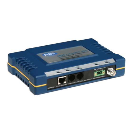
- Page 1 ™ MDS entraNET Series Access Point Remote 900 MHz and 2400 MHz Extended Range IP Networking Transceivers Firmware Release 3.0 MDS 05-4565A01, Rev. A MAY 2007...
- Page 2 Refer to the Installation Reference Chart at the middle of this guide for essential installation and configuration details.
-
Page 3: Table Of Contents
Ethernet Packet Statistics Menu ..........23 Serial Port and Remote Serial Statistics Menu ......25 TECHNICAL ASSISTANCE ..........26 FACTORY SERVICE............. 26 Copyright Notice This publication is protected by copyright law. Copyright 2007, GE MDS, LLC. All rights reserved. 05-4565A01, Rev. A MDS entraNET Start-Up Guide... -
Page 4: Operational & Safety Notices
Manual Revision and Accuracy While every reasonable effort has been made to ensure the accuracy of this manual, product improvements may result in minor differences between the manual and the product shipped to you. If you have questions or need an exact specification for a product, please contact our Technical Services Team using the information at the back of this guide. - Page 5 Environmental Information The manufacture of this equipment has required the extraction and use of natural resources. Improper disposal may contaminate the environment and present a health risk due to hazardous substances contained within. To avoid dissemination of these substances into our environment, and to limit the demand on natural resources, we encourage you to use the appropriate recycling systems for disposal.
-
Page 6: Product Description
• Serial ports—Embedded terminal server for serial interface equipment GE MDS CYBER SECURITY SUITE The operation and management of an enterprise is becoming increas- ingly dependent on electronic information flow. An accompanying concern is the cyber security of the communication infrastructure. -
Page 7: Installation Planning
TANCE” on Page 28 of this guide for information on contacting the MDS Technical Services Group. You will also find support informa- tion at the GE MDS Web site: www.GEmds.com. INSTALLATION STEPS There are three main requirements for installing the transceiver. They are: adequate and stable DC power, a good antenna system, and the correct interface between the transceiver and the data device. - Page 8 Invisible place holder Invisible place holder 7.25˝ (18.4 cm) Figure 1. AP Mounting Bracket Spacing Invisible place holder 6.69˝ (16.99 cm) Figure 2. Remote Mounting Brackets Spacing DIN Rail Mounting Option The radio is available with an optional 35 mm DIN Rail Mounting Bracket (Part No.
-
Page 9: Step 2-Install The Antenna
Invisible place holder Step 2: Snap the assembly onto Step 1: Attach the bracket using the DIN rail. To remove the radio, the two screws provided. (Attach pull down on the release tab. to the end opposite the connectors.) Figure 3. DIN Rail Mounting Details for MDS Equipment Step 2—Install the Antenna To minimize radio frequency interference, the antenna should be mounted at least nine inches (>... -
Page 10: Step 4-Configure The Ap
Invisible place holder Lead Binding Screws (2) Retaining Screws (2) Wire Ports (2) (Polarity: Left +, Right –) Figure 4. DC Power Connector The transceiver must be used only with CAUTION negative-ground systems. Make sure the POSSIBLE POSSIBLE polarity of the power source is correct. The EQUIPMENT EQUIPMENT radio is protected from reverse polarity by... - Page 11 ENTER • Press the key to receive the prompt. The login LED flashes to indicate data communications. COM1 • At the prompt, enter the username ( is the default login admin ENTER username). Press • At the prompt, enter the password ( is the Password admin...
-
Page 12: Step 5-Configure The Remote Radio
Table 2. Key AP Parameters & Menu Item Management Default Values or Range System Location Main Menu >> 9999 1-15 alphanumeric Address Network characters. A good Configuration > choice is the last Wireless MAC four digits of the AP Configuration serial number. -
Page 13: Step 6-Connect The Terminal Equipment
Invisible place holder Invisible place holder Invisible place holder Invisible place holder Invisible place holder Remote COM1 Port PC Running Terminal Session (19,200 bps, 8N1) Figure 5. Remote Configuration Setup b. Login to the remote radio: ENTER • Press several times to receive the prompt. -
Page 14: Step 7-Check For Normal Operation
Ethernet Device Connection to Remote Verify that the Remote port is enabled (on) using the NOTE: command. If it is not, use the command to enable the ETH=ON port. Connect an Ethernet endpoint to the Remote port. The port supports any Ethernet-compatible device. This includes a device that uses the Internet Protocol (IP). - Page 15 Table 3. Transceiver LED Functions LED Label Activity Indication LAN/ETH LAN or endpoint detected Blinking Data TX or RX LAN or endpoint not detected COM1 Blinking Data TX or RX (MGT System) No data activity COM2 Blinking Data TX or RX No data activity Primary power (DC) present Blinking...
-
Page 16: Resetting To Factory Defaults (Use With Care)
b. Check the screen for the Starting Information Device Status (also known as Connection Status). It will show one of the fol- lowing: —The unit is looking for an Access Point beacon Scanning signal. —The unit has found a valid Exp(ecting) Sync(hronization) beacon signal for its network. - Page 17 MAIN MENU Network Security Local Serial Radio Remote Serial Configuration Configuration Configuration Configuration Gateway Approved Remote IP Configuration RF Output COM1/COM2 Port Status RSG Talkback Enable Power Encryption Enable Wireless MAC Config. RSG Talkback Timeout COM1/COM2 Serial Dwell Time Mobility Configuration HTTP Access RSG Entries Configuration Wizard...
- Page 18 INSTALLATION REFERENCE CHART INSTALLATION REFERENCE CHART Detailed instructions are contained in the Reference Manual, P/N 05-4055A01 INSTALLATION SUMMARY Step 1 — Initial Checkout Set the equipment up in a tabletop arrangement. Review the transceiver's Configuration. As a minimum, Access Points must have the following programmed: IP Address, IP Network identifier, and Radio Network Address.
-
Page 19: Aiming Directional Antennas For Maximum Rssi
1. At the login prompt, type authcode. 2. At the password prompt, type authcode. 3. At the authorization prompt, enter the authorization code. (none) login: authcode Password: MDS EntraNET Access Point No directory, logging in with HOME=/ MDS EntraNET Device Name: AP EntraNET 900 Serial Number: 1437374 Enter Authorization Code>... - Page 20 RSSI measurements and Wireless Packet Statistics are based on mul- tiple samples over a period of several seconds. The average of these measurements is displayed by the entraNET MS. The measurement and antenna alignment process usually takes 10 or more minutes at each transceiver. The path to the Management System Menu item is shown in bold text below each step of the procedure.
-
Page 21: Troubleshooting
Technical Assistance If problems cannot be resolved using the guidance provided here, review the GE MDS Web site’s technical support area for recent soft- ware or firmware updates, general troubleshooting help, and service information. Additional help is available through the GE MDS Tech-... -
Page 22: Interpreting The Front Panel Leds
Interpreting the Front Panel LEDs An important set of troubleshooting tools are the LED status indicators on the front panel of the transceiver. They should be checked when- ever a problem is suspected. Table 3 on Page 13 describes the function of each status LED. - Page 23 Table 4. Troubleshooting With LEDs (Continued) Symptom Possible Cause and Resolution LAN/ETH LED does a. Verify that the Ethernet cable is connected at both not turn on. ends. b. Verify that the proper type of Ethernet cable Table (straight-through or crossover) is used. See below for the proper cable type.
-
Page 24: Troubleshooting Using The Embedded Management System
Troubleshooting Using the Embedded Management System If following the suggestions in Table 4 on Page 18 does not resolve the problem, there are some additional tools and techniques that can be used. The Embedded Management System is a good source of infor- mation that may be used remotely to provide preliminary diagnostic information, or may even provide a path to correcting the problem. - Page 25 Table 6. Troubleshooting with the Embedded Management System (Continued) Symptom Possible Cause and Resolution Cannot access a. Check for secure cable connections. The serial the entraNET AP data cable should be as short as possible, never Menu (through exceeding 50 ft./15m. COM1) b.
- Page 26 Table 6. Troubleshooting with the Embedded Management System (Continued) Symptom Possible Cause and Resolution Wireless retry There may be Radio Frequency Interference (RFI). count is too high a. If omnidirectional antennas are used, consider changing to directional antennas. This often limits interference to and from other stations.
-
Page 27: Ethernet Packet Statistics Menu
Ethernet Packet Statistics Menu Figure 7. Sample Packet Statistics Screen This screen provides detailed information on data exchanges between the radio being viewed and the network through the network layer. These include: Wireless Packet Statistics • Packets received • Packets dropped •... - Page 28 The most significant fields are Retries Retry Errors Receive Errors . If the data values are more than 10% of their Lost Carrier Detected sent and received counterparts, or the value is Lost Carrier Detected greater than a few dozen, there may be trouble with interference, or a loss of the Ethernet signal.
-
Page 29: Serial Port And Remote Serial Statistics Menu
Another place to look for trouble is in . The Packets Received by Zone packets should be evenly distributed across all zones (1-5% variation). If they are not, interference in the disparate zones should be suspected. Blocking these zones may eliminate or reduce harmful interference. Serial Port and Remote Serial Statistics Menu Figure 9. -
Page 30: Technical Assistance
TECHNICAL ASSISTANCE Technical assistance for GE MDS products is available from our Technical Support Department during business hours (8:00 A.M.—5:30 P.M. Eastern Time). When calling, please give the complete model number of the radio, along with a description of the trouble symptom(s) you are experiencing. In many cases, problems can be resolved over the telephone, without the need for returning the unit to the factory. - Page 32 GE MDS, LLC 175 Science Parkway Rochester, NY 14620 General Business: +1 585 242-9600 FAX: +1 585 242-9620 Web: www.GEmds.com...