Table of Contents
Advertisement
Quick Links
SERVICE MANUAL
Ver 1.0 2003.03
U.S. and foreign patents licensed from Dolby Laboratories.
MD Player section
Signal-to-noise ratio
Frequency response
Wow and flutter
Tuner section
FM
Tuning range
Aerial terminal
Intermediate frequency
Usable sensitivity
Selectivity
Signal-to-noise ratio
Harmonic distortion at 1 kHz
Separation
Frequency response
MW/LW
Tuning range
Aerial terminal
Intermediate frequency
Sensitivity
Power amplifier section
Outputs
Speaker impedance
Maximum power output
Sony Corporation
9-877-086-01
2003C0500-1
e Vehicle Company
C 2003.03
Published by Sony Engineering Corporation
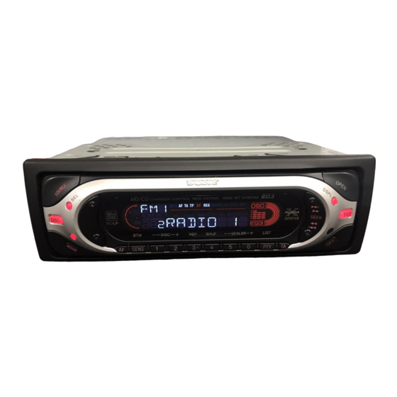
MDX-CA790X
Model Name Using Similar Mechanism
Base Mechanism Type
Optical Pick-up Name
SPECIFICATIONS
General
90 dB
Outputs
10 – 20,000 Hz
Below measurable limit
Inputs
87.5 – 108.0 MHz
External aerial connector
10.7 MHz/450 kHz
9 dBf
75 dB at 400 kHz
67 dB (stereo),
Tone controls
69 dB (mono)
0.5 % (stereo),
0.3 % (mono)
35 dB at 1 kHz
30 – 15,000 Hz
Power requirements
Dimensions
MW: 531 – 1,602 kHz
Mounting dimensions
LW: 153 – 279 kHz
External aerial connector
Mass
10.7 MHz/450 kHz
Supplied accessories
MW: 30 µV
LW: 40 µV
Note
This unit cannot be connected to a digital preamplifier
Speaker outputs
or an equalizer which is Sony BUS system compatible.
(sure seal connectors)
4 – 8 ohms
Design and specifications are subject to change
50 W × 4 (at 4 ohms)
without notice.
Audio outputs (front)
Audio outputs (rear)
Power aerial relay control
terminal
Power amplifier control
terminal
Telephone ATT control
terminal
Remote controller input
terminal
BUS control input terminal
BUS audio input terminal
Low ±10 dB at 60 Hz
(XPLOD)
Mid ±10 dB at 1 kHz
(XPLOD)
High ±10 dB at 10 kHz
(XPLOD)
12 V DC car battery
(negative earth)
Approx. 178 × 50 × 180 mm
(w/h/d)
Approx. 182 × 53 × 161 mm
(w/h/d)
Approx. 1.2 kg
Parts for installation and
connections
Front panel case (1)
FM/MW/LW MINIDISC PLAYER
AEP Model
UK Model
NEW
MG-165A-138
KMS-242E
Advertisement
Table of Contents

Related Manuals for Sony MDX-CA790X


Summary of Contents for Sony MDX-CA790X
- Page 1 Power amplifier section Note This unit cannot be connected to a digital preamplifier Outputs Speaker outputs or an equalizer which is Sony BUS system compatible. (sure seal connectors) Speaker impedance 4 – 8 ohms Design and specifications are subject to change Maximum power output 50 W ×...
-
Page 2: Table Of Contents
LINE WITH MARK 0 ON THE SCHEMATIC DIAGRAMS AND IN THE PARTS LIST ARE CRITICAL TO SAFE OPERATION. REPLACE THESE COMPONENTS WITH SONY PARTS WHOSE PART NUMBERS APPEAR AS SHOWN IN THIS MANUAL OR IN SUPPLEMENTS PUB- LISHED BY SONY. -
Page 3: Servicing Notes
MDX-CA790X SECTION 1 SERVICING NOTES SERVICE POSITION NOTES ON HANDLING THE OPTICAL PICK-UP In checking the key board and main board, prepare two jigs BLOCK OR BASE UNIT (connection cable J-2502-011-1 and The laser diode in the optical pick-up block may suffer electro- connection cable for F/P to main J-2502-071-1). -
Page 4: General
MDX-CA790X SECTION 2 This section is extracted from instruction manual. GENERAL Location of controls AUDIO OUT FRONT AUDIO OUT REAR SEEK BUS AUDIO IN DISC SHUF GP/ALBM LIST SENS BUS CONTROL IN a SOURCE (Power on/Radio/CD* n PTY (programme type) /LIST*... - Page 5 MDX-CA790X Note for the aerial connecting Nota per il collegamento dell’antenna If your car aerial is an ISO (International Se l’antenna dell’auto è di tipo ISO Organisation for Standardisation) type, (International Organization use the supplied adaptor 5 to connect it.
- Page 6 MDX-CA790X Orient the release key correctly. Richten Sie den Löseschlüssel korrekt aus. Face the hook inwards. Der Haken muss nach innen Orientez correctement la clé de déblocage. weisen. Tournez le crochet vers Orientare la chiave di rilascio nel modo corretto.
- Page 7 MDX-CA790X Power connection diagram Schema dei collegamenti di alimentazione Auxiliary power connector may vary depending on the car. Check your car’s auxiliary power connector Il connettore di alimentazione ausiliaria può variare diagram to make sure the connections match a seconda della macchina.
-
Page 8: Disassembly
MDX-CA790X SECTION 3 DISASSEMBLY • This set can be disassembled in the order shown below. 3-1. DISASSEMBLY FLOW Note 1: The process described in can be performed in any order. Note 2: Without completing the process described in , the next process can not be performed. -
Page 9: Sub Panel Assy
MDX-CA790X Note: Follow the disassembly procedure in the numerical order given. 3-2. SUB PANEL ASSY 1 screw (PTT2.6 × 4) 2 cover 4 two claws 7 sub panel assy 4 two claws 3 two screws (PTT2.6 × 6) 6 flexible flat (14 core) cable (CN370) 3-3. -
Page 10: Main Board
MDX-CA790X 3-4. MAIN BOARD 1 three ground point screws (PTT2.6 × 6) 2 four screws (PTT2.6 × 6) 3 main board 3-5. SERVO BOARD 2 four screws (BVTT2 × 4) 3 servo board 1 parallel (FFC) (10core) wire (CN3) 1 optical pick-up flexible board... -
Page 11: Md Cover Assy
MDX-CA790X 3-6. MD COVER ASSY 1 four screws (BVTT2 × 4) 3 MD cover assy shaft (MD cover guide) cassette holder 2 Pushing the cassette holder in the direction of the arrow A with a screwdriver, etc., disengage the shaft (MD cover guide) from the slot in the MD cover assy. -
Page 12: Lever (Le23) Assy
MDX-CA790X 3-8. LEVER (LE23) ASSY 2 stopper washer 3 lever (LE23) assy 4 roller (GLE) 3-9. HOLDER ASSY 4 Remove the holder assy in the direction of the arrow. 2 type-E stop ring 1.5 1 spring (CHKG) 2 type-E stop ring 1.5 2 type-E stop ring 1.5... -
Page 13: Chucking Arm Assy
MDX-CA790X 3-10. CHUCKING ARM ASSY 1 Remove the chucking arm assy in the direction of the arrow. holder assy 3-11. OPTICAL PICK-UP (KMS-242E) 4 screw (B2 × 3) 6 bearing (SL) 5 feed screw assy 7 optical pick-up (KMS-242E) 1 two screws 3 screw (K2 ×... -
Page 14: Motor Assy (Sled) (M902), Sp Motor Assy (Spindle) (M901)
MDX-CA790X 3-12. SL MOTOR ASSY (SLED) (M902), SP MOTOR ASSY (SPINDLE) (M901) 5 screw (P1.7 × 1.8) 0 two screws (P1.7 × 1.8) 6 bracket (SL) 7 SL motor assy (sled) (M902) 3 screw (PS2 × 8) qa retainer (SP) 2 screw (PS2 ×... -
Page 15: Electrical Adjustments
MDX-CA790X SECTION 4 ELECTRICAL ADJUSTMENTS TEST MODE This set have the test mode function. <Set the Test Mode> 1. Turn ON the regulated power supply. (The clock is displayed) [OFF] Note: Press the button, if the clock is not displayed. -
Page 16: Diagrams
MDX-CA790X SECTION 5 DIAGRAMS • IC Block Diagrams – SERVO Board – IC1 CXA2523AR 43 42 USROP – RF AGC – USRC RFA1 BPF3T RFA2 RFA3 PEAK3T – HLPT –1 – – –2 – OFST PTGR TEMP PEAK – –2 –... - Page 17 MDX-CA790X IC2 BH6519FS-E2 INTERFACE INTERFACE CHARGE PREDRIVE PREDRIVE PUMP. PREDRIVE PREDRIVE INTERFACE INTERFACE IC3 R1114N251D-TR-FA REGULATOR VOUT CURRENT LIMIT IC6 BA6287F OUT1 OUT2 DRIVER DRIVER VREF CONTROL LOGIC POWER SAVE...
- Page 18 MDX-CA790X IC4 CXD2667R 112 111 110 109 108 107 106 105 104 103 102 101 100 99 98 93 92 SPINDLE SERVO GFS/SLD EFM/ACIRC DECODER ADIP DECODER ADRB VDIO3 AVS2 VSIO3 AVD2 VDC0 ADRT ADIO MNT0 MNT1 EACH DIGITAL BLOCK...
- Page 19 MDX-CA790X – MAIN Board – IC300 TDA8588AJ/N1 IC400 BA8271F-E2 IC90 SAA6588T/V2-518 OUT-FL- C BUS OUT-FL+ POWER SUPPLY PAUSE RESET & RESET DETECTOR SWITCH MULTI OUT-RL- PATH 57kHz DETECTOR 8th ORDER PGND3 BAND-PASS FILTER OUT-RL+ CLOCKED SIGNAL QUALITY IN-RL COMPARATOR DECODER...
-
Page 20: Block Diagram - Servo Section
MDX-CA790X 5-1. BLOCK DIAGRAM – SERVO Section – MD DSP • R-ch is omitted due to same as L-ch. IC4 (1/2) • SIGNAL PATH DADT : MD PLAY XBCK LRCK FILI FS256 CLTV FILO AOUTL L-CH (PAGE 21) CONVERTER AOUTR... -
Page 21: Block Diagram - Main Section
MDX-CA790X 5-2. BLOCK DIAGRAM – MAIN Section – PJ210 (1/2) INPUT SELECT, ELECTRICAL VOLUME AUDIO IN IC120 R-CH PJ210 (2/2) OUT-FR FADER TONE CONTROL/ L-CH INPUT INPUT (PAGE 20) MUTE VOLUME EFFECT SELECTOR GAIN OUT-RR MUTING CIRCUIT AUDIO OUT FADER... -
Page 22: Block Diagram - Panel/Bus Control/Power Supply Section
MDX-CA790X 5-3. BLOCK DIAGRAM – PANEL/BUS CONTROL/POWER SUPPLY Section – CNJ400 SONY BUS INTERFACE IC400 BUS CONTROL IN RESET RESET SWITCH MD MECHANISM CONTROLLER IC7 (2/2) D405 (1/2) DATA I/O DATA IN UNISO UNISO UNISO DATA UNISI UNISI MDMON_CHECK LO_6V... -
Page 23: Note For Printed Wiring Boards And Schematic Diagrams
MDX-CA790X 5-4. NOTE FOR PRINTED WIRING BOARDS AND SCHEMATIC DIAGRAMS • Circuit Boards Location Note on Printed Wiring Board: Note on Schematic Diagram: • X : parts extracted from the component side. • All capacitors are in µF unless otherwise noted. pF: µµF •... -
Page 24: Schematic Diagram - Servo Section (1/2)
MDX-CA790X 5-5. SCHEMATIC DIAGRAM – SERVO Section (1/2) – • • See page 31 for Waveforms. See page 16 for IC Block Diagrams. (1/2) 6.3V 0.01 10µH +2.5V REGULATOR M901 TP16 (SP-BLK) SPDL- (SPINDLE) R114N251B-TR TP17 (SP+RED) SPDL+ TP18 (SL+RED) -
Page 25: Schematic Diagram - Servo Section (2/2)
MDX-CA790X 5-6. SCHEMATIC DIAGRAM – SERVO Section (2/2) – • • See page 31 for Waveform. See page 16 for IC Block Diagram. (2/2) DISC_EXIST DISC_EXIST MD_ON MD-ON EJECT-OK EJECT_OK DISC_IN MDMON MECHA-ON LOAD_END OPEN_REQ LOADING MOTOR DRIVE OPEN_REQ LIMIT... -
Page 26: Printed Wiring Boards - Servo Section
MDX-CA790X 5-7. PRINTED WIRING BOARDS – SERVO Section – • See page 23 for Circuit Boards Location. • Semiconductor Location Ref. No. Location MAIN BOARD SERVO BOARD CNP500 SERVO BOARD (SIDE A) (Page 27) (SIDE B) BP5 BP6 F-15 R5 R4... -
Page 27: Printed Wiring Boards - Main Section
MDX-CA790X 5-8. PRINTED WIRING BOARDS – MAIN Section – • See page 23 for Circuit Boards Location. • Semiconductor Location (FRONT VIEW) PJ210 J370 Ref. No. Location BUS AUDIO AUDIO OUT AUDIO OUT REMOTE IN REAR FRONT CNJ400 SERVO BOARD... - Page 28 MDX-CA790X 5-9. SCHEMATIC DIAGRAM – MAIN Section (1/3) – • • See page 31 for Waveform. See page 16 for IC Block Diagrams. PJ210 (1/3) AUDIO OUT BUS AUDIO REAR FRONT TU10 TUX-030 (FM/AM TUNER PACK) C305 C306 C307 0.22 0.22...
-
Page 29: Schematic Diagram - Main Section (2/3)
MDX-CA790X 5-10. SCHEMATIC DIAGRAM – MAIN Section (2/3) – • See page 31 for Waveforms. (Page 28) (2/3) JC610 R611 JC611 JC17 C600 100p Q600 DTA114EKA R617 KEY ACTIVE SWITCH IC601 R607 PST3428UL 100k R600 ADON 100k JC504 DEST2 AMPATT TELATT MECH6.0V... -
Page 30: Schematic Diagram - Main Section (1/3)
R700 100k D375 CN371 CN372 R375 MA111 RCIN1 D701 RCIN0 J370 MA2YD1500L REMOTE IN (Page 29) DOORIND RESET SONY BUS INTERFACE CNJ400 JC403 UNI_SI BUS CONTROL IN R408 IC400 220k JC407 BA8271F-E2 BU_IN D405 MA721WK BUS ON DATA UNI_SO BUS DATA... -
Page 31: Printed Wiring Board - Sub Section
MDX-CA790X 5-12. PRINTED WIRING BOARD – SUB Section – • See page 23 for Circuit Boards Location. • Waveforms – MAIN Board – – SERVO Board – 1 IC1 1, 2 (I, J) 6 IC7 i; (X0) qa IC90 4 (OSCO) -
Page 32: Printed Wiring Board - Key Section
MDX-CA790X 5-14. PRINTED WIRING BOARD – KEY Section – • See page 23 for Circuit Boards Location. KEY BOARD (SIDE A) LED954 LED911, 951, 952 (KEY ILLUMINATION) LSW912 S902 R935 DSPL SOURCE LSW905 LSW904 LSW913 LCD901 LIQUID CRYSTAL DISPLAY SEEK +... -
Page 33: Schematic Diagram - Key Section
MDX-CA790X 5-15. SCHEMATIC DIAGRAM – KEY Section – • See page 31 for Waveform. R972 R981 R982 LED903,911,951-954 REMOTE CONTROL (KEY ILLUMINATION) RECEIVER R983 IC971 RS-770 LSW919(2/2) LED933 LED954 LED903 LSW912(2/2) LSW913(2/2) LSW915(2/2) LSW905(2/2) SEG60 SEG41 NSCW505T-ARS CL-195SR CL-195SR C971... -
Page 34: Ic Pin Function Description
MDX-CA790X 5-16. IC PIN FUNCTION DESCRIPTION • SERVO BOARD IC1 CXA2523AR (RF AMP, FOCUS/TRACKING ERROR AMP) • SERVO BOARD IC4 CXD2667R (MD DSP) Pin No. Pin Name Description Pin No. Pin Name Description GFS/SLD GFS output or sled servo drive signal output terminal Not used... - Page 35 MDX-CA790X Pin No. Pin Name Description Address signal output terminal Not used VSIO1 — Ground terminal Output enable signal output terminal Not used XCAS Column address strobe signal output terminal Not used Address signal output terminal Not used XRAS Row address strobe signal output terminal Not used...
- Page 36 MDX-CA790X Pin No. Pin Name Description DDOUT Open terminal in this set ASYO Playback EFM full-swing output terminal ASYI Playback EFM asymmetry comparator voltage input terminal AVD1 — Power supply terminal (+3.3V) BIAS Playback EFM asymmetry circuit constant current input terminal...
- Page 37 Pin Name Description MDMON Power supply on/off control signal output of the MD mechanism deck section LINKOFF Uni-link on/off control signal output for the SONY bus interface “L”: link on ERR-PWM Error rate PWM output terminal Not used Not used 3TPWM...
- Page 38 MDX-CA790X Pin No. Pin Name Description Not used ADER-PWM ADIP error PWM output terminal Not used 61 to 68 For test terminal Not used Power supply detection of MD mechanism deck section (MDMON) MDMON_CHECK Power supply detection of servo section (MDON)
- Page 39 UNISO Serial data output to the SONY bus interface IC UNISI Serial data input from the SONY bus interface IC Serial data transfer clock signal output to the SONY bus interface IC and MD mechanism UNICKO controller 36 to 38...
- Page 40 MDX-CA790X Pin No. Pin Name Description DIAG DIAG signal input from the power amplifier VOLATT Muting on/off control signal output to the electrical volume NCO (AUX) Not used NOSESW Front panel remove/attach detection signal input terminal “L”: front panel is attached...
-
Page 41: Exploded Views
MDX-CA790X SECTION 6 EXPLODED VIEWS NOTE: • -XX and -X mean standardized parts, so they • Items marked “*” are not stocked since they The components identified by mark 0 or dotted line with mark may have some difference from the original are seldom required for routine service. -
Page 42: Front Panel Section
MDX-CA790X 6-2. FRONT PANEL SECTION not supplied not supplied not supplied not supplied not supplied supplied not supplied not supplied not supplied supplied (key board) supplied LCD901 Ref. No. Part No. Description Remark Ref. No. Part No. Description Remark A-3337-390-A PANEL COMPLETE ASSY, FRONT... -
Page 43: Mechanism Deck Section-1 (Mg-165A-138)
MDX-CA790X 6-3. MECHANISM DECK SECTION-1 (MG-165A-138) mechanism deck section-2 Ref. No. Part No. Description Remark Ref. No. Part No. Description Remark A-3274-602-A SERVO BOARD, COMPLETE * 106 3-220-096-02 BRACKET (DAMPER) * 102 X-3379-367-2 CHASSIS ASSY, MD * 107 3-034-301-01 CUSHION (EJ2) -
Page 44: Mechanism Deck Section-2 (Mg-165A-138)
MDX-CA790X 6-4. MECHANISM DECK SECTION-2 (MG-165A-138) not supplied not supplied mechanism deck section-3 Ref. No. Part No. Description Remark Ref. No. Part No. Description Remark * 151 X-3381-040-1 HOLDER ASSY 3-032-707-01 SPRING (LEVER LE) 3-032-682-01 SPRING (HOLDER) 3-925-034-01 ROLLER (GLE) -
Page 45: Mechanism Deck Section-3 (Mg-165A-138)
MDX-CA790X 6-5. MECHANISM DECK SECTION-3 (MG-165A-138) (including M903) M901 M902 The components identified by mark 0 or dotted line with mark 0 are critical for safety. Replace only with part number specified. Ref. No. Part No. Description Remark Ref. No. -
Page 46: Electrical Parts List
MDX-CA790X SECTION 7 ELECTRICAL PARTS LIST NOTE: • Due to standardization, replacements in the • Items marked “*” are not stocked since they The components identified by mark 0 or dotted line with mark parts list may be different from the parts speci- are seldom required for routine service. - Page 47 MDX-CA790X MAIN Ref. No. Part No. Description Remark Ref. No. Part No. Description Remark R921 1-216-833-11 METAL CHIP 1/10W 1-124-584-00 ELECT 100uF R927 1-216-025-11 RES-CHIP 1/10W 1-162-970-11 CERAMIC CHIP 0.01uF R928 1-216-021-00 METAL CHIP 1/10W 1-162-970-11 CERAMIC CHIP 0.01uF R929...
- Page 48 MDX-CA790X MAIN Ref. No. Part No. Description Remark Ref. No. Part No. Description Remark C322 1-124-234-00 ELECT 22uF C323 1-162-970-11 CERAMIC CHIP 0.01uF < DIODE > C324 1-124-234-00 ELECT 22uF 8-719-069-55 DIODE UDZSTE-175.6B C325 1-162-970-11 CERAMIC CHIP 0.01uF 8-719-069-54 DIODE UDZSTE-175.1B...
- Page 49 MDX-CA790X MAIN Ref. No. Part No. Description Remark Ref. No. Part No. Description Remark JC141 1-216-864-11 METAL CHIP 1/10W 1-216-809-11 METAL CHIP 1/10W 1-216-821-11 METAL CHIP 1/10W JC142 1-216-864-11 METAL CHIP 1/10W 1-216-833-11 METAL CHIP 1/10W JC300 1-216-296-11 SHORT CHIP...
- Page 50 MDX-CA790X MAIN MINI JACK SENSOR SERVO Ref. No. Part No. Description Remark Ref. No. Part No. Description Remark R372 1-216-821-11 METAL CHIP 1/10W < TUNER PACK > R373 1-216-821-11 METAL CHIP 1/10W TU10 A-3220-887-A TUNER UNIT (TUX-030) R374 1-216-821-11 METAL CHIP...
- Page 51 MDX-CA790X SERVO Ref. No. Part No. Description Remark Ref. No. Part No. Description Remark 1-125-837-11 CERAMIC CHIP 6.3V < RESISTOR > 1-117-863-11 CERAMIC CHIP 0.47uF 6.3V 1-164-245-11 CERAMIC CHIP 0.015uF 1-218-863-11 METAL CHIP 4.7K 0.5% 1/10W 1-164-360-11 CERAMIC CHIP 0.1uF...
- Page 52 MDX-CA790X SERVO Ref. No. Part No. Description Remark Ref. No. Part No. Description Remark 1-216-845-11 METAL CHIP 100K 1/10W 1-216-845-11 METAL CHIP 100K 1/10W 1-216-853-11 METAL CHIP 470K 1/10W 1-216-819-11 METAL CHIP 1/10W 1-218-727-11 METAL CHIP 1/10W 1-216-839-11 METAL CHIP...