Table of Contents

Related Manuals for HP J2000


Summary of Contents for HP J2000
- Page 1 Maintaining and Operating the HPE J2000 Flash Enclosure Abstract This guide describes how to maintain and operate the HPE J2000 Flash Enclosure and its associated hardware components. Part Number: P39049-001 Published: March 2021 Edition: 1...
- Page 2 © Copyright 2021 Hewlett Packard Enterprise Development LP Notices The information contained herein is subject to change without notice. The only warranties for Hewlett Packard Enterprise products and services are set forth in the express warranty statements accompanying such products and services. Nothing herein should be construed as constituting an additional warranty.
-
Page 3: Table Of Contents
FRU replacement...........................................15 System status LEDs........................................15 Location of service labels......................................16 Removing the optional front bezel from the rack............................17 Extending the J2000 from the rack...................................17 Releasing the cable management arm................................17 Replacing drives..........................................18 Replacing an I/O module......................................18 Replacing a fan module......................................19 Replacing a power module...................................... - Page 4 Remote support..........................................25 Warranty information......................................... 25 Regulatory information......................................25 Documentation feedback......................................26...
-
Page 5: Introduction
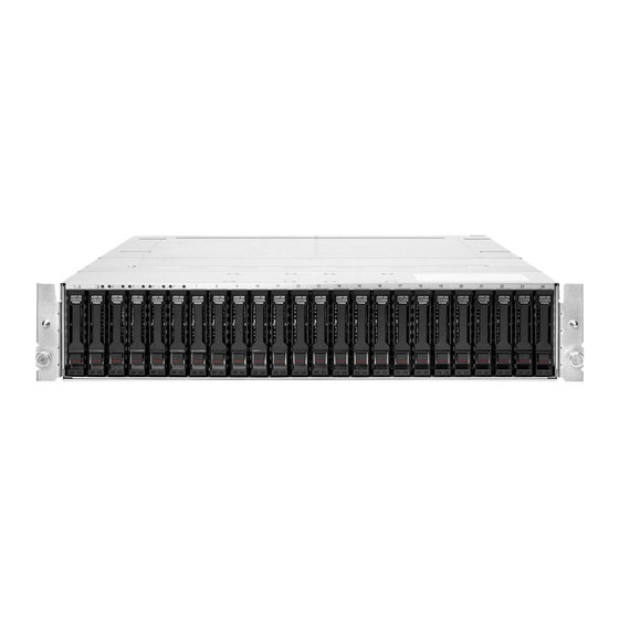
Introduction The HPE J2000 Flash Enclosure, or HPE J2000 NVMe-oF JBOF, is a highly available system with no single point of failure (SPOF). The server class baseboard management controllers (BMCs) provide redundant system management. The 2U enclosure fits inside a standard 48.3 cm (19 in) rack. System power is provided by two 1+1 redundant power modules. -
Page 6: Operation
Operation WebUI overview The J2000 WebUI enables system administrators to connect the NVMe-oF bridge adapter card(s) to a target NVMe Qualified Name (NQN) for each drive and to set up the hosts. SYSTEM SUMMARY The SYSTEM SUMMARY is a static display of high-level system information at the top of the window. Below the system summary are tabs for system management and information: CHASSIS, DRIVES, HOSTS, IOMS, BRIDGES, and INVENTORY. -
Page 7: Hosts Tab
Color Drive status Critical Yellow Warning Green Good Gray Not installed White Disabled HOSTS tab The HOSTS tab enables you to view information about and manage hosts (add, remove, edit). You can access the disks ™ that utilize the NVMe-oF bridge adapter through the WebUI. - Page 8 For more information, see LDAP configuration settings. LDAP configuration settings Authentication The J2000 must authenticate to access the LDAP directory. The authentication type is the user name and password (UsernameAndPassword). The user name and password are used to bind to the LDAP server. Search Settings Search settings provides the following fields for looking up information in the user directory: NOTE: Search setting fields are case-sensitive.
-
Page 9: Setting The System Time
URL form, and can be in Lightweight Directory Application Protocol (LDAP) or Secure LDAP (LDAPS) - for example, ldaps://DC-Alpha.MyCompany.com:636. Groups must be expressed with the full Common Name notation - for example, CN=J2000- Admin,OU=J2000,DC=MyCompany,DC=com. Setting the system time You can synchronize the network clocks by using the Network Time Protocol (NTP), or you can set the time manually. -
Page 10: Viewing And Downloading Logs
Procedure 1. Select the FIRMWARE tab from the Admin Dashboard. 2. Under Upload new firmware, click Choose file, and then select the appropriate firmware file. A list of targets as determined by the firmware contained in the file is displayed. Possible targets include I/O modules, bridges, and the WebUI. -
Page 11: Adding Drive Namespaces
• To enable events, click the Event service enabled toggle button. • To set the number of retry attempts, enter the number in the Retry attempts box. To set the retry interval, enter the number of seconds in the Retry intervals (in seconds) box. •... -
Page 12: Editing A Host
5. (Optional) Select the edit icon (green pencil) to update the host details. Editing a host Prerequisites Requires Administrator or Operator privileges A host has been added to the J2000 on the HOSTS tab. Procedure 1. In the WebUI, click HOSTS. 2. Select the host you want to edit. -
Page 13: Restarting The I/O Module
• Netmask • Gateway 6. Click Save. 7. Close the Settings window by clicking the X in the upper right corner of the window. Restarting the I/O module Prerequisites Requires Administrator or Operator privileges Procedure 1. In the WebUI, click the IOMs tab. 2. -
Page 14: Editing Bridge Settings
Editing bridge settings Prerequisites Requires Administrator or Operator privileges Procedure 1. Navigate to the BRIDGES tab. 2. Select a bridge. The selected bridge is identified following the list of installed bridges; for example, IOM 1 | Bridge 1. 3. Edit the following bridge settings according to your requirements. When changing most bridge settings, a confirmation prompt appears. -
Page 15: Maintenance
System status LEDs Nine system status LEDs are located along the top-left edge of the front of the J2000, just above the drive bays. The first three LEDs provide system status. The next six LEDs provide field-replaceable unit (FRU) group status for the FRUs that are not visible from the front of the J2000—the fans, I/O modules, and power modules. -
Page 16: Location Of Service Labels
Function LED color Behavior Chassis power Green On: The J2000 is powered on and operating correctly. Off: The J2000 is not powered on. IOM fault Yellow On: One or more I/O modules have experienced a fault requiring a service action. -
Page 17: Removing The Optional Front Bezel From The Rack
The J2000 must be extended from the rack to access and service the system fan modules. You do not need to extend the J2000 from the rack to access and service the hot-swappable power modules and I/O modules. -
Page 18: Replacing Drives
Press the release handle downward until the release latch connects with the release catch and the drive sets into place. Verify that the drive is installed properly in the drive bay so that it is flush with the face of the J2000. 10. Repeat the preceding steps for all remaining drives. -
Page 19: Replacing A Fan Module
I/O option slot on the rear of the J2000. 10. Push the I/O module into the J2000 until the lock bar engages and the module is flush with the front of the J2000. Never force the module into place. -
Page 20: Replacing A Power Module
3. Insert the replacement fan module in the same orientation as the removed fan module, with the connector on the left with the connector on the left front of the J2000. 4. Insert the J2000 back into the rack. - Page 21 If both power modules have failed, shut down the system power. Procedure Unplug the power cord from the power module jack on the back of the J2000. Remove both power cords if replacing both power modules. Press the power module release tab (top of power module) toward the finger handle while pulling the finger handle outward to disengage the power module cam.
-
Page 22: Securing The Cable Management Arm
Pull the finger handle outward slightly to verify that the power module is locked in place. If you can remove the power module from the J2000 without pushing the power module release tab, remove the power module, repeat steps 5 through 7, and then retest the installation. -
Page 23: Websites
Websites General websites Single Point of Connectivity Knowledge (SPOCK) Storage compatibility matrix https://www.hpe.com/storage/spock Storage white papers and analyst reports https://www.hpe.com/storage/whitepapers For additional websites, see Support and other resources. Websites... -
Page 24: Support And Other Resources
Support and other resources Accessing Hewlett Packard Enterprise Support • For live assistance, go to the Contact Hewlett Packard Enterprise Worldwide website: https://www.hpe.com/info/assistance • To access documentation and support services, go to the Hewlett Packard Enterprise Support Center website: https://www.hpe.com/support/hpesc Information to collect •... - Page 25 IMPORTANT: Access to some updates might require product entitlement when accessed through the Hewlett Packard Enterprise Support Center. You must have an HPE Passport set up with relevant entitlements. Remote support Remote support is available with supported devices as part of your warranty or contractual support agreement. It provides intelligent event diagnosis, and automatic, secure submission of hardware event notifications to Hewlett Packard Enterprise, which will initiate a fast and accurate resolution based on your product's service level.
- Page 26 Additional regulatory information Hewlett Packard Enterprise is committed to providing our customers with information about the chemical substances in our products as needed to comply with legal requirements such as REACH (Regulation EC No 1907/2006 of the European Parliament and the Council). A chemical information report for this product can be found at: https://www.hpe.com/info/reach For Hewlett Packard Enterprise product environmental and safety information and compliance data, including RoHS and REACH, see:...