Siemens SIMATIC ET 200SP Manual
Hide thumbs
Also See for SIMATIC ET 200SP:
- System manual (320 pages) ,
- Manual (270 pages) ,
- Operating instructions manual (166 pages)
Table of Contents
Advertisement
Quick Links
Advertisement
Table of Contents

Related Manuals for Siemens SIMATIC ET 200SP


Summary of Contents for Siemens SIMATIC ET 200SP
- Page 2 Interface Module IM 155-6 PN R1 (6ES7155-6AU00-0HM0) Preface ET 200SP Documentation Guide SIMATIC Product overview Wiring ET 200SP Interface Module IM 155-6 PN R1 (6ES7155-6AU00-0HM0) Parameter Interrupts, error messages, diagnostics and system Equipment Manual alarms Compatibility Technical specifications Dimension drawing 11/2022 A5E51160307-AA...
- Page 3 Note the following: WARNING Siemens products may only be used for the applications described in the catalog and in the relevant technical documentation. If products and components from other manufacturers are used, these must be recommended or approved by Siemens. Proper transport, storage, installation, assembly, commissioning, operation and maintenance are required to ensure that the products operate safely and without any problems.
-
Page 4: Preface
Purpose of the documentation This Equipment Manual supplements the System Manual Distributed I/O system ET 200SP (https://support.industry.siemens.com/cs/ww/en/view/58649293). Functions that generally relate to the system are described in this manual. The information provided in this manual and in the system/function manuals supports you in commissioning the ET 200SP distributed I/O system. - Page 5 Siemens' products and solutions undergo continuous development to make them more secure. Siemens strongly recommends that product updates are applied as soon as they are available and that the latest product versions are used. Use of product versions that are no longer supported, and failure to apply the latest updates may increase customers' exposure to cyber threats.
-
Page 6: Table Of Contents
Table of contents Preface ..............................3 ET 200SP Documentation Guide ......................7 Information classes ET 200SP ....................7 Basic tools ........................... 9 MultiFieldbus Configuration Tool (MFCT) ................10 SIMATIC Technical Documentation ..................11 Product overview ..........................13 Properties .......................... 13 Functions .......................... - Page 7 Table of contents Parameter ............................29 Parameters ........................29 Status of the supply voltage L+ of the I/O modules ............. 29 Substitute value behavior ....................29 Interrupts, error messages, diagnostics and system alarms ............... 31 Status and error displays ....................31 Interrupts ..........................
-
Page 8: Et 200Sp Documentation Guide
ET 200SP Documentation Guide Information classes ET 200SP The documentation for the SIMATIC ET 200SP distributed I/O system is arranged into three areas. This arrangement enables you to access the specific content you require. You can download the documentation free of charge from the Internet (https://support.industry.siemens.com/cs/ww/en/view/109742709). - Page 9 You can find the latest Product Information on the ET 200SP distributed I/O system on the Internet. (https://support.industry.siemens.com/cs/de/en/view/73021864) Manual Collection ET 200SP The Manual Collection contains the complete documentation on the SIMATIC ET 200SP distributed I/O system gathered together in one file. You can find the Manual Collection on the Internet.
-
Page 10: Basic Tools
(https://support.industry.siemens.com/cs/ww/en/view/109767888) SINETPLAN SINETPLAN, the Siemens Network Planner, supports you in planning automation systems and networks based on PROFINET. The tool facilitates professional and predictive dimensioning of your PROFINET installation as early as in the planning stage. In addition, SINETPLAN supports you during network optimization and helps you to exploit network resources optimally and to plan reserves. -
Page 11: Multifieldbus Configuration Tool (Mfct)
MultiFieldbus- and DALI-devices. In addition, the MFCT offers convenient options for mass firmware updates of ET 200 devices with MultiFieldbus- support and reading service data for many other Siemens devices. Functional scope of the MFCT • MultiFieldbus configuration:... -
Page 12: Simatic Technical Documentation
Online Support: Industry Online Support International (https://support.industry.siemens.com/cs/ww/en/view/109742705) Watch this short video to find out where you can find the overview directly in Siemens Industry Online Support and how to use Siemens Industry Online Support on your mobile device: Quick introduction to the technical documentation of automation products per video (https://support.industry.siemens.com/cs/us/en/view/109780491) - Page 13 Manuals, characteristics, operating manuals, certificates • Product master data You can find "mySupport" on the Internet. (https://support.industry.siemens.com/My/ww/en) Application examples The application examples support you with various tools and examples for solving your automation tasks. Solutions are shown in interplay with multiple components in the system - separated from the focus on individual products.
-
Page 14: Product Overview
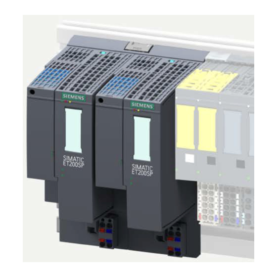
Product overview Properties Article number 2x 6ES7155-6AU00-0HM0 (interface module IM 155-6 PN R1) 1x 6ES7193-6BR00-0HM0 (BaseUnit BU type M0 and server module) Figure 2-1 View of the ET 200SP R1 and the server module Properties The special feature of the ET 200SP R1 system is the high availability due to redundant PROFINET connections. - Page 15 Product overview 2.1 Properties Note The IM 155-6 PN R1 cannot be pulled/plugged when the corresponding supply voltage plug is plugged in. Note BusAdapter of the same type Note that only BusAdapters of the same type are supported on both interface modules. Accessories The following accessories can be ordered separately: •...
- Page 16 – BaseUnit BU type M0 for two IM 155-6 PN R1 incl. server module and two 24 V DC connectors Information on the BaseUnits is available in the BaseUnits (https://support.industry.siemens.com/cs/ww/en/view/59753521) equipment manual. • Labeling strips • Reference identification label You can find more information on the accessories in the ET 200SP Distributed I/O System (https://support.industry.siemens.com/cs/ww/en/view/58649293) system manual.
- Page 17 • There is no supply voltage L+ to least one digital output module and • Feedback voltage is present You can find more information in the server module (https://support.industry.siemens.com/cs/ww/en/view/63257531) manual. First I/O BaseUnit of an ET 200SP in the configuration Note...
-
Page 18: Functions
• Firmware update via PROFINET IO • Identification data I&M 0 to I&M 3 You can find more information on the system functions in the ET 200SP Distributed I/O System system manual (https://support.industry.siemens.com/cs/ww/en/view/58649293). Note Redundant firmware update You can only perform a redundant firmware update via MFCT. - Page 19 Firmware version Configuring with Configuring with of the module as of the module as GSD file TIA Portal V18 (https://support.i and higher ndustry.siemens. com/cs/ww/en/vi ew/57138621) Supported Ethernet services: ICMP, ARP, V6.0.0 SNMP, LLDP Port diagnostics V6.0.0 Disabling of ports V6.0.0 Minimum update time 1 ms V6.0.0...
-
Page 20: Supported Ethernet Services: Icmp, Arp, Snmp, Lldp
Product overview 2.2 Functions 2.2.1 Supported Ethernet services: ICMP, ARP, SNMP, LLDP Supported Ethernet services: ICMP, ARP, SNMP, LLDP The module supports the following standardized Ethernet services: • ICMP - Internet Control Message Protocol (RFC 792) ICMP is a protocol used to transmit informational and error messages over the Internet protocol. -
Page 21: Device Replacement Without Programming Device (Pg) And Without Topological Configuration
If the IO devices were already used in another configuration, reset them to factory settings before reusing them. You can find information on this in the system manual Distributed I/O system ET 200SP (https://support.industry.siemens.com/cs/ww/en/view/58649293). You can find additional information in the STEP 7 online help and as of STEP 7 (TIA Portal) V12 in the PROFINET with STEP 7 (https://support.industry.siemens.com/cs/ww/en/view/49948856) function manual. -
Page 22: Media Redundancy Protocol (Mrp)
You can find additional information in the STEP 7 online help and as of STEP 7 (TIA Portal) V12 in the PROFINET with STEP 7 (https://support.industry.siemens.com/cs/ww/en/view/49948856) function manual. 2.2.7 Distribution of module channels to a maximum of 4 submodules... -
Page 23: Use Of Fail-Safe Modules
(Page 45). Only the failure of both connections results in a station failure. R1 mode is possible in both line and ring topology (MRP) and any other topologies. You can find more information on individual topologies in the ET 200SP Distributed I/O System (https://support.industry.siemens.com/cs/ww/en/view/58649293) system manual. 2.2.11 Value status of I/O modules Value status The IM 155-6 PN R1 interface module supports I/O modules with value status. -
Page 24: Reading Out Service Data
In the case of a pending maintenance alarm, you can read out the service data and make it available to SIEMENS support for queries and product improvement. The service data is read out using the TCP protocol. A connection on port 102 is opened for this. -
Page 25: Setting The Time
The interface module supports time setting, for example, with AI Energy Meter 480VAC/CT HF (6ES7134-6PA00-0CU0). In an application example (https://support.industry.siemens.com/cs/ww/en/view/109754890) we show you how to set the time of day. Note that you call the block "Sync_Time_ET200SP" in the user program for each hardware identifier of the two IM 155-6 interface modules of a redundant ET 200SP R1 station. -
Page 26: Removal/Insertion Of Multiple I/O Modules During Operation (Multi Hot Swap)
Firmware update via PROFINET IO Firmware update via PROFINET IO You can find information on how to perform a firmware update in the ET 200SP Distributed I/O System system manual (https://support.industry.siemens.com/cs/ww/en/view/58649293). Interface Module IM 155-6 PN R1 (6ES7155-6AU00-0HM0) Equipment Manual, 11/2022, A5E51160307-AA... -
Page 27: Identification Data I&M 0 To I&M 3
With TIA Portal, you can read out the identification data I&M (see online help of the TIA Portal). You can find additional information on the identification data I&M 0 to I&M 3 in the ET 200SP distributed I/O system System Manual (https://support.industry.siemens.com/cs/ww/en/view/58649293). Interface Module IM 155-6 PN R1 (6ES7155-6AU00-0HM0) Equipment Manual, 11/2022, A5E51160307-AA... -
Page 28: Wiring
Note Pin assignment BusAdapter You can find information on pin assignment of the BusAdapter under: PROFINET IO BusAdapter (https://support.industry.siemens.com/cs/ww/en/view/109773801) Reference You can find more information on accessories and how to connect the interface module in the Distributed I/O system ET 200SP (https://support.industry.siemens.com/cs/ww/en/view/58649293) system manual. -
Page 29: Schematic Circuit Diagram
Wiring 3.2 Schematic circuit diagram Schematic circuit diagram Schematic circuit diagram The following figure shows the block diagram of the IM 155-6 PN R1 interface module. ① Switch 24 V DC supply voltage ② ET 200SP backplane bus interface and Ground electronics ③... -
Page 30: Parameter
You configure the ET 200SP R1 on a redundant S7-1500H system. Status of the supply voltage L+ of the I/O modules You can find information on the status of the supply voltage L+ of the I/O modules in the Server module (https://support.industry.siemens.com/cs/ww/en/view/63257531) equipment manual. Substitute value behavior The substitute value behavior in the ET 200SP distributed I/O system is executed by the IO controller for each slot. - Page 31 Parameter 4.3 Substitute value behavior The "current-free/voltage-free" behavior takes effect in the following cases: • Incorrectly configured module • Module with incorrect parameter assignment Interface Module IM 155-6 PN R1 (6ES7155-6AU00-0HM0) Equipment Manual, 11/2022, A5E51160307-AA...
-
Page 32: Interrupts, Error Messages, Diagnostics And System Alarms
Interrupts, error messages, diagnostics and system alarms Status and error displays LED displays The figure below shows the LED indicators on the interface modules and on the BusAdapters: ① RN (green) ② ER (red) ③ MT (yellow) ④ LK1 (green) ⑤... - Page 33 Interrupts, error messages, diagnostics and system alarms 5.1 Status and error displays RN/ER/MT LEDs on the interface module Table 5- 1 Status and error displays of RN/ER/MT LEDs LEDs Meaning Remedy (RUN) (ERROR) (MAINT) Missing or insufficient supply voltage Check the supply voltage or turn it on at the on interface module.
- Page 34 Interrupts, error messages, diagnostics and system alarms 5.1 Status and error displays ACT LED on the interface module Status display of the ACT LED ACT LED Meaning There is no active data exchange with the I/O modules via this interface module. Active data exchange with the I/O modules is taking place via this interface module.
- Page 35 Interrupts, error messages, diagnostics and system alarms 5.1 Status and error displays LED display of configuration errors Configuration errors of the ET 200SP distributed IO system are indicated on the interface module via the red ERROR LED and the yellow MAINT LED. The following configuration errors are indicated by the LEDs: •...
- Page 36 • RN, ER and MT LED: Off More information on the BusAdapters and their status and error displays is available in the BusAdapter (https://support.industry.siemens.com/cs/ww/en/view/109751716) manual. Show not supported BusAdapter The LEDs RN (flashes), ER (flashes) and MT (off) on the interface module indicate that no supported BusAdapter has been inserted.
-
Page 37: Interrupts
S7-1500 CPU, the CPU web server and the HMI device. You will find more information on system diagnostics in the Diagnostics (https://support.industry.siemens.com/cs/ww/en/view/59192926) function manual. Interface Module IM 155-6 PN R1 (6ES7155-6AU00-0HM0) Equipment Manual, 11/2022, A5E51160307-AA... -
Page 38: Triggering Of A Diagnostics Interrupt
Interrupts, error messages, diagnostics and system alarms 5.2 Interrupts 5.2.1 Triggering of a diagnostics interrupt Triggering of a diagnostics interrupt For an incoming or outgoing event (e.g. wire break on a channel of an I/O module), the module triggers a diagnostics interrupt if this is configured accordingly. The CPU interrupts the processing of the user program and processes the diagnostics interrupt OB (OB 82). -
Page 39: Triggering Of A Pull/Plug Interrupt
Interrupts, error messages, diagnostics and system alarms 5.2 Interrupts 5.2.3 Triggering of a pull/plug interrupt Triggering of a pull/plug interrupt In the event of a pull/plug interrupt, the CPU interrupts processing of the user program and processes the pull/plug OB (OB 83). The event that triggered the interrupt is entered in the start information of the pull/plug OB. -
Page 40: Alarms
Interrupts, error messages, diagnostics and system alarms 5.3 Alarms Alarms Introduction The ET 200SP distributed I/O system generates the following alarms: • Diagnostic alarms • Maintenance alarms 5.3.1 Diagnostics alarms Actions after a diagnostic alarm There can be more than one diagnostics alarm at the same time. Each diagnostic alarm initiates the following actions: •... - Page 41 *) Read the service data according to the description in the manual and send them to the SIEMENS Customer Support for root cause analysis. PROFINET IO Another source of diagnostic events is the PROFINET basic technology in use. It generates diagnostics messages containing coding that is already defined in the PROFINET IO Standard - Application Layer Service Definition V2.2.
-
Page 42: Maintenance Alarms
Interrupts, error messages, diagnostics and system alarms 5.3 Alarms 5.3.2 Maintenance alarms 5.3.2.1 Maintenance alarms Maintenance alarms A maintenance event is generated each time a maintenance requirement is identified. The maintenance LED on the interface module lights up in yellow. Note Maintenance messages have no direct effect on the module function. - Page 43 Customer Support for root cause analysis. *) Read the service data according to the description in the manual and send them to the SIEMENS Customer Support for root cause analysis. **) As described in the ET 200SP Distributed I/O System system manual...
-
Page 44: Automatic Restart Of The Interface Module In Case Of Error
If the error leads to a maintenance alarm "Hardware error: Increased disturbances detected", read out the service data from the device and make it available to SIEMENS support for queries and product improvement. Only reading out service data leads to the reset of the Maintenance LED display. - Page 45 You can find additional information on the bumpless changeover of modules in the Product Information on the Internet (https://support.industry.siemens.com/cs/ww/en/view/73021864). Operation of modules in isochronous mode Since the ET 200SP R1 system does not support isochronous mode, there is a corresponding functional limitation with modules (e.g.
-
Page 46: Compatibility
Compatibility 6.1 Compatibility of modules For some modules, this behavior may result in error messages or state errors in related instructions. Therefore, you must evaluate the error messages for these instructions and react to them in an application-specific manner. The following table shows affected modules and instructions. Table 6- 2 Modules and instructions that require an application-specific error response Modules... - Page 47 Technical specifications Technical specifications of IM 155-6 PN R1 The following table shows the technical specifications as of 11/2022. You can find a data sheet including daily updated technical specifications on the Internet (https://support.industry.siemens.com/cs/de/en/pv/6ES7155-6AU00-0HM0/td?dl=en). Article number 6ES7155-6AU00-0HM0 General information Firmware version V6.0...
-
Page 48: Technical Specifications
Technical specifications Article number 6ES7155-6AU00-0HM0 Hardware configuration Integrated power supply Yes; 24 V DC Rack • Modules per rack, max. Submodules • Number of submodules per station, max. Interfaces Number of PROFINET interfaces 1; 2 ports (switch) 1. Interface Interface types 2;... - Page 49 Technical specifications Article number 6ES7155-6AU00-0HM0 MRPD – Open IE communication • TCP/IP • SNMP • LLDP Interrupts/diagnostics/status information Status indicator Alarms Diagnostics function Diagnostics indication LED Yes; green LED • RUN LED Yes; red LED • ERROR LED Yes; Yellow LED •...
-
Page 50: Dimension Drawing
Dimension drawing This appendix contains the dimension drawing of the ET 200SP R1 including its BaseUnit, mounted on a SIMATIC system rail. You must take into account the dimensions for installation in cabinets, control rooms, etc. Figure A-1 Dimension drawing for ET 200SP R1 (front and side view) Interface Module IM 155-6 PN R1 (6ES7155-6AU00-0HM0) Equipment Manual, 11/2022, A5E51160307-AA...