Advertisement
Quick Links
T
ECHNICAL INFORMATION
Models No.
Description
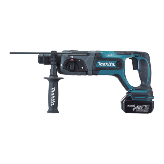
C
ONCEPT AND MAIN APPLICATIONS
The cordless version of HR2470 has been launched
with D-handle for operator's comfort.
This new product is available in the following variations.
Model No.
BHR241RFE
BL1830
BHR241RF
BHR241Z
The variations for USA, Canada, Mexico and Panama are as follows.
Model No.
BHR241
BL1830
BHR241Z
S
pecification
No load speed : (min
Blows per min, :(bpm=min
Max. Output(W)
Voltage: V
Battery
Cell and Capacity
Charging Time: min.
Chuck Capacity: mm ( " )
Bit Shank
Steel
Capacity
Wood
: mm ( " )
* Concrete
Operation mode
R= Rotation only
H+R= Hammering with Rotation
H= Hammering only
Variable switch
Reverse switch
Clutch (Torque Limiter)
Electric Brake
Net Weight : kg (lbs)
S
tandard equipment
* Grip assembly ................................... 1 set
Note: The standard equipment for the tool shown above may differ by country.
O
ptional accessories
* SDS-Plus bits
* Taper shank T.C.T bits
* Taper shank adapter
* Cotter
* Drill chuck assembly
* Chuck adapter
* Drill chuck S13
BHR241
Cordless Combination Hammer
Battery
Charger
Type
Quantity
2
DC18RA
1
No
---
No
Battery
Charger
Type
Quantity
2
DC18RA
No
---
No
= rpm)
-1
-1)
3.2 (7.0) including Battery BL1830
[3.5 (7.7) measured by EPTA regulation]
* Chuck key S13
* Keyless drill chuck
* Grip assembly
* Scraper Assembly
* Cold chisels
* Grooving chisels
* Scaling chisels
See more at http://safe-manuals.com
Plastic
carrying case
Yes
Yes
No
Plastic
carrying case
Yes
No
0 - 1,100
0 - 4,000
330
18
Li-ion 3.0 Ah
22 with DC18RA
10 (3/8)
SDS-plus
13 (1/2)
26 (1-1/16)
20 (13/16)
3 modes
(R/ H+R/ H)
Yes
Yes
Yes
Yes
* Depth gauge (Stopper pole) .............. 1 pc.
* Bull points
* Dust Cup
* Grease Vessel 30g
* Blow out bulb
* Safety goggle
* Dust extractor attachment
* Joint 25
PRODUCT
P 1/ 14
L
W
Dimensions: mm (")
Length (L)
417 (16-3/8)
Width (W)*
84 (3-5/16)
Height (H)
219 (8-5/8)
* excludes Grip assembly
* Concrete: 24 (15/16)
for North America
* Charger DC18RA
* Charger DC18SC
* Charger DC24SA
* Charger DC24SC
* Battery BL1830
* Hammer service kit
H
Advertisement

Related Manuals for Makita BHR241RF


Summary of Contents for Makita BHR241RF
- Page 1 Type Quantity Dimensions: mm (") BHR241RFE DC18RA BL1830 Length (L) 417 (16-3/8) BHR241RF Width (W)* 84 (3-5/16) BHR241Z Height (H) 219 (8-5/8) The variations for USA, Canada, Mexico and Panama are as follows. * excludes Grip assembly Battery Plastic Model No.
-
Page 2: Necessary Repairing Tools
Removing / Installing Ring spring 29 from / to Tool holder complete [2] LUBRICATION Apply the following grease to protect parts and product from unusual abrasion. * Makita grease R No.00 to the portions marked with black triangle * Molybdenum disulfide lubricant to the portions marked with gray triangle Item No. - Page 3 Description Portion to lubricate Lubricant Amount O ring 16 Whole portion Makita grease R No. 00 (f) Inside where Striker moves (g) Hole for accepting Piston joint Piston cylinder (h) Surface where 30 Tool holder complete contacts. Molybdenum disulfide (Refer to Fig. 1.) lubricant Gear teeth where 28 Spur gear 51 engages (Refer to Fig.
- Page 4 P 4/ 14 epair [3] DISASSEMBLY/ASSEMBLY [3] -2. Change Lever DISASSEMBLING Disassemble Change lever as illustrated in Figs. 4 and 5. Fig. 4 Fig. 5 Change lever Drill mode Lock button Pushing Lock button into Change lever, Remove Change lever by levering up it with Slotted head screwdriver, turn Change lever fully to Drill mode inserted between Gear housing complete and Change lever.
- Page 5 P 5/ 14 epair [3] DISASSEMBLY/ASSEMBLY [3] -4. Armature DISASSEMBLING 1) Remove Holder cap cover by inserting Slotted screwdriver between Holder cap cover and Motor housing complete. (Fig. 8) Then remove Holder cap and Carbon brushes. 2) Seperate Gear housing complete from Motor housing complete by loosening 4x40 Tapping screws (4 pcs.). Armature is left on Gear housing complete in this step.
- Page 6 P 6/ 14 epair [3] DISASSEMBLY/ ASSEMBLY [3] -5. Torque Limiter Section (cont.) ASSEMBLING Do the reverse of disassembling steps. Note: Do not forget to assemble Flat washer 28 between Torque limiter section and Inner housing complete. Refer to Fig. 12. [3] DISASSEMBLY/ASSEMBLY [3] -6.
- Page 7 P 7/ 14 epair [3] DISASSEMBLY/ASSEMBLY [3] -7. Impact Bolt Section DISASSEMBLI NG 1) Referring to "[3] -5. Torque Limiter Section", disassemble Ring spring 29, Washer 31, Compression spring 32 and Spur gear 51 from Tool holder complete. Refer to Figs. 11 to 14. 2) Holding Gear housing complete in vise and 1R038, Tap Ring spring 28 in Tool holder complete as illustrated in Figs.
- Page 8 P 8/ 14 epair [3] DISASSEMBLY/ASSEMBLY [3] -7. Impact Bolt Section (cont.) ASSEMBLING 2) Push Ring spring 28 with Piston cylinder until it fits to the inner groove of Tool holder complete. (Fig. 29) Fig. 29 Note: Use an extra Piston cylinder as a jig. Never use Piston cylinder that is to be assembled to the machine.
- Page 9 P 9/ 14 epair [3] DISASSEMBLY/ASSEMBLY [3] -8. Swash Bearing Section (cont.) DISASSEMBLING 6) Move Piston cylinder to the rear dead center position (Fig. 32). 7) Remove Swash bearing section from Inner housing by pulling in the direction of the arrow. Then, remove Change plate from the groove of Clutch cam.
- Page 10 P 10/ 14 epair [3] DISASSEMBLY/ASSEMBLY [3] -8. Swash Bearing Section (cont.) DISASSEMBLING 11) Remove Helical gear 26 using 1R022, 1R023 and 1R281. as illustrated to left in Fig. 37. Swash bearing 10 and Clutch cam can now be removed by hand (right in Fig. 37). 12) Remove Retaining ring S-7 using 1R291 (left in Fig.
- Page 11 2) Assemble Piston joint and two Flat washers 12 to Piston cylinder as illustrated in Fig. 40. Note: Do not forget to apply Makita grease R No.00. Refer to Fig. 2. 3) Insert Piston cylinder into Inner housing complete. (Fig. 41).
- Page 12 P 12/ 14 epair [3] DISASSEMBLY/ASSEMBLY [3]-9. F/R change lever, Wave washer, Cushion and Rubber pin 5 in Housing set ASSEMBLING Refer to Fig. 47. Fig. 47 Fit the protrusion of Switch into Oval hole of F/R change lever and assemble them to Housing L. Wave washer 15 Do not forget to put Wave washer 15 in place for...
-
Page 13: Maintenance Program
P 13/ 14 aintenance program It is recommended to replace the following parts shown below and apply lubricant to the specific parts designated in Figs.2 and 3 when replacing Carbon brushes. 1 Cap 35 29 Steel ball 7.0 40 O ring 16 35 Cushion ring 13 37 O ring 9... -
Page 14: Wiring Diagram
P 14/ 14 iring diagram Fig. D-2 Connecting terminal Switch Housing set (L) Bend Connecting terminal to Housing set (L) side as Fix the Brush holder’s Lead wires illustrated above. (red and black) with Lead wire holder. Yoke unit Switch Heat sink Put the extra portion of Lead wires in this...