Table of Contents
Advertisement
Quick Links
Specifications
Power Source
AC 100~240V, 50/60Hz
Power Consumption
Average use: 49W
Stand-by condition: 4W
TV set: DC 15V, 2.8 A max.
LCD
15.2-inch (385mm), 16:9 aspect ratio LCD panel
Screen Size
13.21-inch (335.6mm) (W) x 7.43-inch (188.6mm)(H) x 15.2-
inch (385.0mm)(Diagonal)
Sound
Speaker
Tweeter (3 x 4cm 2pcs, 89), Woofer (Ø5cm, 89)
Audio Output
6.5W (2.0W+2.0W+2.5W (Woofer)), 10%THD
Headphones
M3(3.5 mm) Jack x 1 89 impedance
FEATURES
®
Aero-Hammer
Woofer System (2Way 3Speaker System)
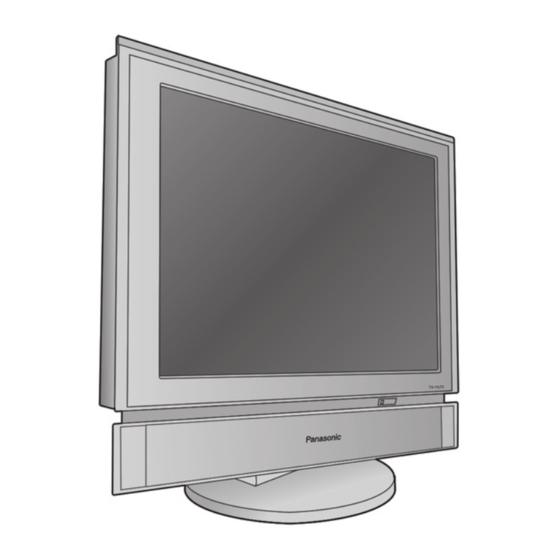
15.2" Diagonal LCD TV
TX-15LT2M
TX-15LT2Q
TX-15LT2Z
TX-15LT2X
TX-15LT2T
LH1 Chassis
Receiving System
Receiving Channels
Regular TV
VHF BAND
2-12 (PAL/SECAM B, K1)
0-12 (PAL B AUST.)
1-9 (PAL B N.Z)
1-12 (PAL/SECAM D)
1-12 (NTSC M Japan)
2-13 (NTSC M U.S.A)
UHF BAND
21-69 (PAL G, H, I/SECAM G, K, K1)
28-69 (PAL B AUST.)
13-57 (PAL D, K)
© 2003 Matsushita Electric Industrial Co., Ltd. All
rights
reserved.
distribution is a violation of law.
ORDER NO. ITD0303001C2
Unauthorized
copying
and
Advertisement
Table of Contents

Related Manuals for Panasonic TX-15LT2M


Summary of Contents for Panasonic TX-15LT2M
- Page 1 ORDER NO. ITD0303001C2 15.2” Diagonal LCD TV TX-15LT2M TX-15LT2Q TX-15LT2Z TX-15LT2X TX-15LT2T LH1 Chassis Specifications Power Source Receiving System AC 100~240V, 50/60Hz Power Consumption Average use: 49W Stand-by condition: 4W TV set: DC 15V, 2.8 A max. 15.2-inch (385mm), 16:9 aspect ratio LCD panel Screen Size 13.21-inch (335.6mm) (W) x 7.43-inch (188.6mm)(H) x 15.2-...
-
Page 2: Table Of Contents
TX-15LT2M / TX-15LT2Q / TX-15LT2Z / TX-15LT2X / TX-15LT2T 13-62 (NTSC M Japan) VIDEO 14-69 (NTSC M U.S.A) RCA PIN Type x 1 14-69 (NTSC M U.S.A) S-VIDEO CATV Mini DIN 4-pin S1-S20 (OSCAR) AUDIO L-R 1-125 (U.S.A CATV) RCA PIN Type × 2... - Page 3 TX-15LT2M / TX-15LT2Q / TX-15LT2Z / TX-15LT2X / TX-15LT2T 11.14. P-Board Schematic Diagram 12.3. Mechanical Replacement Parts List 12 Parts Location & Mechanical Replacement Parts List 13 Replacement Parts List 12.1. Parts Location 13.1. Replacement Parts List Notes 12.2. Packing Exploded View...
-
Page 4: Safety Precautions
TX-15LT2M / TX-15LT2Q / TX-15LT2Z / TX-15LT2X / TX-15LT2T 1 Safety Precautions 1.1. General Guidelines 1. When servicing, observe the original lead dress. If a short circuit is found, replace all parts which have been overheated or damaged by the short circuit. -
Page 5: Prevention Of Electro Static Discharge (Esd) To
TX-15LT2M / TX-15LT2Q / TX-15LT2Z / TX-15LT2X / TX-15LT2T 2 Prevention of Electro Static Discharge (ESD) to Electrostatically Sensitive (ES) Devices Some semiconductor (solid state) devices can be damaged easily by static electricity. Such components commonly are called Electrostatically Sensitive (ES) Devices. Examples of typical ES devices are integrated circuits and some field-effect transistors and semiconductor "chip"... -
Page 6: About Lead Free Solder (Pbf)
TX-15LT2M / TX-15LT2Q / TX-15LT2Z / TX-15LT2X / TX-15LT2T 3 About lead free solder (PbF) Note: Lead is listed as (Pb) in the periodic table of elements. In the information below, Pb will refer to Lead solder, and PbF will refer to Lead Free Solder. -
Page 7: Self Check
TX-15LT2M / TX-15LT2Q / TX-15LT2Z / TX-15LT2X / TX-15LT2T 4 Self Check 1. Self-Check is used to automatically check the bus lines and hexadecimal code of the TV set. 2. To get into the Self -Check mode press the [ Down (... -
Page 8: Chasis Board Layout
TX-15LT2M / TX-15LT2Q / TX-15LT2Z / TX-15LT2X / TX-15LT2T 6 Chasis Board Layout... -
Page 9: Servicing Method
TX-15LT2M / TX-15LT2Q / TX-15LT2Z / TX-15LT2X / TX-15LT2T 7 Servicing method 7.1. Removing tilt base... -
Page 10: Removing Rear Panel
TX-15LT2M / TX-15LT2Q / TX-15LT2Z / TX-15LT2X / TX-15LT2T 7.2. Removing rear panel 7.3. Removing speaker unit... -
Page 11: Removing Front Panel
TX-15LT2M / TX-15LT2Q / TX-15LT2Z / TX-15LT2X / TX-15LT2T 7.4. Removing front panel 7.5. Removing LCD panel... -
Page 12: Removing Main A-Board
TX-15LT2M / TX-15LT2Q / TX-15LT2Z / TX-15LT2X / TX-15LT2T 7.6. Removing main A-Board... -
Page 13: Removing B-Board (With Tuner Assembly)
TX-15LT2M / TX-15LT2Q / TX-15LT2Z / TX-15LT2X / TX-15LT2T 7.7. Removing B-Board (with tuner assembly) -
Page 14: Removing Dg-Board
TX-15LT2M / TX-15LT2Q / TX-15LT2Z / TX-15LT2X / TX-15LT2T 7.8. Removing DG-Board 7.9. Removing H-Board... -
Page 15: Removing P-Board
TX-15LT2M / TX-15LT2Q / TX-15LT2Z / TX-15LT2X / TX-15LT2T 7.10. Removing P-Board 7.11. Removing K-Board 7.12. Pull out the flexible cable straight to the coupler. -
Page 16: Removing Back-Light
TX-15LT2M / TX-15LT2Q / TX-15LT2Z / TX-15LT2X / TX-15LT2T 7.13. Removing back-light 7.14. A-Board servicing * Follow the procedures described below when checking voltage on rear side of the A-Board. -
Page 17: Service Mode Function
TX-15LT2M / TX-15LT2Q / TX-15LT2Z / TX-15LT2X / TX-15LT2T 8 Service Mode Function MPU controls the functions switching for each IICs through IIC bus in this chassis. The following setting and adjustment can be adjusted by remote control in Service Mode. - Page 18 TX-15LT2M / TX-15LT2Q / TX-15LT2Z / TX-15LT2X / TX-15LT2T...
-
Page 19: Option Description
TX-15LT2M / TX-15LT2Q / TX-15LT2Z / TX-15LT2X / TX-15LT2T 8.3. Option Description Option Models Description M Q Z X T option1 Colour system Auto(1) SECAM(1) NTSC(1) M.NTSC(1) TV NTSC 50 Reserved TV SECAM 60 Reserved AV NTSC 50 Reserved AV SECAM 60... - Page 20 TX-15LT2M / TX-15LT2Q / TX-15LT2Z / TX-15LT2X / TX-15LT2T Option Models Description M Q Z X T option8 Teletext CH Refresh Enable(1) Geomagnetic Sensor set to 0 Geomagnetic Polarity set to 0 RF Attenuation Enable(1) Fine tuning Enable(1) Search speed...
-
Page 21: Option Code Setting
If the memory IC (IC1004) or DG Board is replaced, option code should be re-memorized. Spare part of IC1004 is already memorized all Data for TX-15LT2M/Z. If you use for other model, you should re-memorized the different option code in SERVICE 2 mode. -
Page 22: Adjustment
TX-15LT2M / TX-15LT2Q / TX-15LT2Z / TX-15LT2X / TX-15LT2T 9 Adjustment 9.1. RF AGC Adjustment 1. Connect RF signal generator to antenna terminal. 2. Receive a RF signal, Colour bar. 3. Enter service 1 mode, and select RF AGC. 4. Adjustment begins when the blue button of the remote controller is pushed. - Page 23 Connect the earth of instruments to the earth connection of the circuit being measured. d. Make sure to disconnect the power plug before removing the chassis. 2. Following diodes are interchangeable. MA150- MA162 (Replacement part) TX-15LT2M/Q/T/X/Z Schematic Diagram Notes...
- Page 24 TX-15LT2M/Q/T/X/Z Power Block Diagram TX-15LT2M/Q/T/X/Z Power Block Diagram...
- Page 25 TX-15LT2M/Q/T/X/Z Signal Block Diagram TX-15LT2M/Q/T/X/Z Signal Block Diagram...
- Page 26 TX-15LT2M/Q/T/X/Z Signal Block Diagram TX-15LT2M/Q/T/X/Z Signal Block Diagram...
- Page 27 Q2302 TP4019 IC2502 Q2303 IC2503 TP4207 Q2504 IC4001 TP4209 Q2505 IC4002 Q2506 IC4003 Q2510 IC4004 Q2511 TRANSISTOR Q2512 Q2517 Q001 Q2518 Q003 Q4001 Q004 Q4002 Q005 Q4003 Q802 Q4004 Q803 Q4005 Q806 Q4006 Q808 TX-15LT2M/Q/T/X/Z TX-15LT2M/Q/T/X/Z A-BOARD TNPA0529 A-BOARD TNPA0529...
- Page 28 Q813 TP811 Q814 TP812 Q815 TP813 Q817 TP814 Q818 TP815 Q819 TP816 Q820 TP817 Q821 TP818 Q2301 TP819 Q2302 TP820 Q2303 TP844 Q2501 TP2323 Q2502 TP2324 Q2503 TP2331 Q2513 TP2332 Q2514 TP2333 Q2515 TP2334 TX-15LT2M/Q/T/X/Z TX-15LT2M/Q/T/X/Z A-BOARD TNPA0529 A-BOARD TNPA0529...
- Page 29 P-BOARD (COMPONENT SIDE) TNPA2770 Parts Location P-BOARD (COMPONENT SIDE) TRANSISTOR IC601 Q609 Q612 IC602 Q614 Q615 Q616 Q617 TX-15LT2M/Q/T/X/Z TX-15LT2M/Q/T/X/Z B-BOARD TXN/B10HGK H-BOARD TNPA2774 K-BOARD TNPA2773 B-BOARD TXN/B10HGK H-BOARD TNPA2774 K-BOARD TNPA2773 P-BOARD TNPA2770 V-BOARD TNPA2772 P-BOARD TNPA2770 V-BOARD TNPA2772...
- Page 30 TRANSISTOR Q601 TP601 Q602 TP602 Q603 TP603 Q604 TP604 Q605 TP605 Q606 TP606 Q607 Q608 Q610 Q611 Q613 TX-15LT2M/Q/T/X/Z TX-15LT2M/Q/T/X/Z B-BOARD TXN/B10HGK H-BOARD TNPA2774 K-BOARD TNPA2773 B-BOARD TXN/B10HGK H-BOARD TNPA2774 K-BOARD TNPA2773 P-BOARD TNPA2770 V-BOARD TNPA2772 P-BOARD TNPA2770 V-BOARD TNPA2772...
-
Page 31: Dg-Board
TXNDG10HGK Parts Location DG-BOARD (COMPONENT SIDE) IC1002 TP6001 TP6002 IC1005 IC1006 TP6003 IC1007 TP6004 IC1008 TP6005 IC3002 TP9503 TP9504 IC6001 IC6302 TP9505 IC6307 IC9001 IC9502 IC9505 TRANSISTOR Q1010 Q6001 Q6002 Q6003 Q9502 Q9503 Q9504 TX-15LT2M/Q/T/X/Z TX-15LT2M/Q/T/X/Z DG-BOARD TXNDG10HGK DG-BOARD TXNDG10HGK... - Page 32 IC3004 Q3002 IC6002 Q6301 IC6301 Q6302 IC6303 Q6303 IC6304 Q6304 IC6305 Q9001 IC6306 Q9002 IC9501 Q9003 IC9503 Q9004 IC9504 Q9501 TRANSISTOR Q9505 Q9506 Q901 Q9507 Q902 Q903 Q904 TP9058 Q905 TP9506 Q906 TP9507 Q907 TX-15LT2M/Q/T/X/Z TX-15LT2M/Q/T/X/Z DG-BOARD TXNDG10HGK DG-BOARD TXNDG10HGK...
- Page 33 TX-15LT2M/Q/T/X/Z TX-15LT2M/Q/T/X/Z A-Board (1 of 4) Schematic Diagram A-Board (1 of 4) Schematic Diagram...
- Page 34 TX-15LT2M/Q/T/X/Z TX-15LT2M/Q/T/X/Z A-Board (2 of 4) Schematic Diagram A-Board (2 of 4) Schematic Diagram...
- Page 35 TX-15LT2M/Q/T/X/Z TX-15LT2M/Q/T/X/Z A-Board (3 of 4) Schematic Diagram A-Board (3 of 4) Schematic Diagram...
- Page 36 TX-15LT2M/Q/T/X/Z TX-15LT2M/Q/T/X/Z A-Board (4 of 4) Schematic Diagram A-Board (4 of 4) Schematic Diagram...
- Page 37 TX-15LT2M/Q/T/X/Z B,H,K,and V-Board Schematic Diagram TX-15LT2M/Q/T/X/Z B,H,K,and V-Board Schematic Diagram...
- Page 38 TX-15LT2M/Q/T/X/Z DG-Board (1 of 5) Schematic Diagram TX-15LT2M/Q/T/X/Z DG-Board (1 of 5) Schematic Diagram...
- Page 39 TX-15LT2M/Q/T/X/Z DG-Board (2 of 5) Schematic Diagram TX-15LT2M/Q/T/X/Z DG-Board (2 of 5) Schematic Diagram...
- Page 40 TX-15LT2M/Q/T/X/Z TX-15LT2M/Q/T/X/Z DG-Board (3 of 5) Schematic Diagram DG-Board (3 of 5) Schematic Diagram...
- Page 41 TX-15LT2M/Q/T/X/Z TX-15LT2M/Q/T/X/Z DG-Board (4 of 5) Schematic Diagram DG-Board (4 of 5) Schematic Diagram...
- Page 42 TX-15LT2M/Q/T/X/Z TX-15LT2M/Q/T/X/Z DG-Board (5 of 5) Schematic Diagram DG-Board (5 of 5) Schematic Diagram...
- Page 43 TX-15LT2M/Q/T/X/Z TX-15LT2M/Q/T/X/Z P-Board Schematic Diagram P-Board Schematic Diagram...
-
Page 44: Block And Schematic Diagrams
) is found, connection is easily found from the direction of arrow 9. Indicates the major signal flow. : Video Audio 10. This schematic diagram is the latest at the time of printing and subject to change without notice. TX-15LT2M/Q/T/X/Z Schematic Diagram Notes... - Page 45 Connect the earth of instruments to the earth connection of the circuit being measured. d. Make sure to disconnect the power plug before removing the chassis. 2. Following diodes are interchangeable. MA150- MA162 (Replacement part) TX-15LT2M/Q/T/X/Z Schematic Diagram Notes...
-
Page 46: Power Block Diagram
11.2. Power Block Diagram TX-15LT2M/Q/T/X/Z Power Block Diagram... - Page 47 TX-15LT2M/Q/T/X/Z Power Block Diagram...
- Page 48 TX-15LT2M/Q/T/X/Z Power Block Diagram...
- Page 49 TX-15LT2M/Q/T/X/Z Power Block Diagram...
-
Page 50: Signal Block Diagram
11.3. Signal Block Diagram TX-15LT2M/Q/T/X/Z Signal Block Diagram... - Page 51 TX-15LT2M/Q/T/X/Z Signal Block Diagram...
- Page 52 TX-15LT2M/Q/T/X/Z Signal Block Diagram...
- Page 53 TX-15LT2M/Q/T/X/Z Signal Block Diagram...
-
Page 54: A-Board (1 Of 4) Schematic Diagram
11.4. A-Board (1 of 4) Schematic Diagram TX-15LT2M/Q/T/X/Z A-Board (1 of 4) Schematic Diagram... - Page 55 TX-15LT2M/Q/T/X/Z A-Board (1 of 4) Schematic Diagram...
-
Page 56: A-Board (2 Of 4) Schematic Diagram
11.5. A-Board (2 of 4) Schematic Diagram TX-15LT2M/Q/T/X/Z A-Board (2 of 4) Schematic Diagram... - Page 57 TX-15LT2M/Q/T/X/Z A-Board (2 of 4) Schematic Diagram...
-
Page 58: A-Board (3 Of 4) Schematic Diagram
11.6. A-Board (3 of 4) Schematic Diagram TX-15LT2M/Q/T/X/Z A-Board (3 of 4) Schematic Diagram... - Page 59 TX-15LT2M/Q/T/X/Z A-Board (3 of 4) Schematic Diagram...
-
Page 60: A-Board (4 Of 4) Schematic Diagram
11.7. A-Board (4 of 4) Schematic Diagram TX-15LT2M/Q/T/X/Z A-Board (4 of 4) Schematic Diagram... - Page 61 TX-15LT2M/Q/T/X/Z A-Board (4 of 4) Schematic Diagram...
-
Page 62: Dg-Board (1 Of 5) Schematic Diagram
11.8. DG-Board (1 of 5) Schematic Diagram TX-15LT2M/Q/T/X/Z DG-Board (1 of 5) Schematic Diagram... - Page 63 TX-15LT2M/Q/T/X/Z DG-Board (1 of 5) Schematic Diagram...
-
Page 64: Dg-Board (2 Of 5) Schematic Diagram
11.9. DG-Board (2 of 5) Schematic Diagram TX-15LT2M/Q/T/X/Z DG-Board (2 of 5) Schematic Diagram... - Page 65 TX-15LT2M/Q/T/X/Z DG-Board (2 of 5) Schematic Diagram...
-
Page 66: Dg-Board (3 Of 5) Schematic Diagram
11.10. DG-Board (3 of 5) Schematic Diagram TX-15LT2M/Q/T/X/Z DG-Board (3 of 5) Schematic Diagram... - Page 67 TX-15LT2M/Q/T/X/Z DG-Board (3 of 5) Schematic Diagram...
-
Page 68: Dg-Board (4 Of 5) Schematic Diagram
11.11. DG-Board (4 of 5) Schematic Diagram TX-15LT2M/Q/T/X/Z DG-Board (4 of 5) Schematic Diagram... - Page 69 TX-15LT2M/Q/T/X/Z DG-Board (4 of 5) Schematic Diagram...
-
Page 70: Dg-Board (5 Of 5) Schematic Diagram
11.12. DG-Board (5 of 5) Schematic Diagram TX-15LT2M/Q/T/X/Z DG-Board (5 of 5) Schematic Diagram... - Page 71 TX-15LT2M/Q/T/X/Z DG-Board (5 of 5) Schematic Diagram...
-
Page 72: B, H, K, And V-Board Schematic Diagram
11.13. B, H, K, and V-Board Schematic Diagram TX-15LT2M/Q/T/X/Z B,H,K,and V-Board Schematic Diagram... - Page 73 TX-15LT2M/Q/T/X/Z B,H,K,and V-Board Schematic Diagram...
- Page 74 11.14. P-Board Schematic Diagram TX-15LT2M/Q/T/X/Z P-Board Schematic Diagram...
- Page 75 TX-15LT2M/Q/T/X/Z P-Board Schematic Diagram...
- Page 76 Option Models Description M Q Z X T option1 Colour system Auto(1) SECAM(1) NTSC(1) M.NTSC(1) TV NTSC 50 Reserved TV SECAM 60 Reserved AV NTSC 50 Reserved AV SECAM 60 Reserved option2 CH Plan ASIA / M.E. / HK / UK / CHINA (1) NZ / INDES (1) AUSTRALIA (1) E.
- Page 77 Option Models Description M Q Z X T option8 Teletext CH Refresh Enable(1) Geomagnetic Sensor set to 0 Geomagnetic Polarity set to 0 RF Attenuation Enable(1) Fine tuning Enable(1) Search speed Slow(1) Fast(0) TEXT FLOF Reserved TEXT TOP TOP enable (1) option9 free free...
- Page 78 ) is found, connection is easily found from the direction of arrow 9. Indicates the major signal flow. : Video Audio 10. This schematic diagram is the latest at the time of printing and subject to change without notice. TX-15LT2M/Q/T/X/Z Schematic Diagram Notes...
- Page 79 TX-15LT2M/Q/T/X/Z Power Block Diagram TX-15LT2M/Q/T/X/Z Power Block Diagram...