
Related Manuals for ABB HVC-PD


Summary of Contents for ABB HVC-PD
- Page 1 — I N STA LL ATIO N GU IDE HVC-PD E-Bus Charger Installation Guide for NA products Version 1.2...
- Page 2 ABB cannot be held liable for errors in the translation. This document and parts thereof must not be reproduced or copied without written permission from ABB, and the contents there of must not be imparted to a third party nor used for any unauthorized purpose.
- Page 3 HVC‐PD E‐Bus Charger Installation Guide Version control Version Date Remarks 20-5-20201 First release 23-09-2021 Changed figures cabinet and added notice for WiFi device 30-06-2022 Updated based on NA requirements Document: V1.2 / Document No.: 6AGA000008-0629-EN | Date: 06-30-2022 Page 3 of 146...
-
Page 4: Table Of Contents
1.6. Cyber Security Disclaimer 1.7. Contact information Description of the product 2.1. Overview of the system 2.1.1. Standard HVC-PD 150 kW E-Bus Charger system 2.1.2. Standard HVC-PD 300 kW E-Bus Charger system 2.1.3. Standard HVC-PD 450 kW E-Bus Charger system 2.1.4. - Page 5 HVC‐PD E‐Bus Charger Installation Guide 4.1. About construction 4.2. Construct foundation of the Power Cabinet 4.2.1. Options 4.2.2. Workflow with concrete foundation 4.2.3. Workflow with metal frame foundation 4.2.3.1. HPC175-HVC150 MET FOUND KIN 8IN – NAM (2CEB489802R0001) 4.2.4. Workflow mounting Power Cabinet direct on a floor (footprint) 4.3.
- Page 6 HVC‐PD E‐Bus Charger Installation Guide 5.9.2. Connect the communication fiber cables 5.10. Close the door of the Power Cabinet 5.11. Unpack the Charge Pole 5.11.1. Before unpacking 5.11.2. Remove packaging 5.12. Move the Charge pole to position 5.13. Install Charge Pole onto the foundation 5.14.
- Page 7 HVC‐PD E‐Bus Charger Installation Guide Dimensions Junction Box Dimensions Charge pole Clearance and vertical working range of the pantograph Dimensions Concrete Foundation Power Cabinet Dimensions Metal Foundation Power Cabinet Dimensions Concrete Foundation Pole Power Cabinet – Outline with Foundation Signal Ground overview of the system Document: V1.2 / Document No.: 6AGA000008-0629-EN | Date: 06-30-2022 Page 7 of 146...
- Page 8 User computers systems within a limited area. The owner of an electric vehicle, who uses the Charge Station to charge that vehicle. ABB Network Operating Centre; remotely checks the correct functioning of the WiFi charger. A technology that allows electronic devices to connect to a wireless LAN (WLAN) network.
-
Page 9: Introduction
This guide describes the planning and physical installation of the HVC-PD E-Bus Charger with a “fold-out” charge Pole at its location. The HVC-PD E-Bus Charger is a DC fast charger system for hybrid or electrical buses that are compatible with the OPP Charging standard . -
Page 10: Safety Regulations
HVC‐PD E‐Bus Charger Installation Guide WARNING Pinch Hazard Identifies a hazard that could result in injuries in which some body parts are pinched or crushed. WARNING Fall Hazard Identifies a hazard that could result in injury due unsafe work at height. CAUTION Various Identifies a hazard that could result in damage to the machine, other equipment, and/or environmental pollution. -
Page 11: Tilting And Handling
ABB’s warranty policy. Neither ABB nor its affiliates shall be liable to the purchaser of this product or third parties for damages, losses, costs or expenses incurred by purchaser or third parties... -
Page 12: Electric Hazards
Instruct and warn people about the potential harmful high voltages. 5. The installation and maintenance personnel must supply their own lighting equipment, since the HVC-PD E-Bus Charger has no lights inside the cabinet. 6. Always connect the Protective Earth (PE) first, before connecting the neutral (N) and Phase (P) wiring. -
Page 13: Environment And Disposal Of Waste
ABB Ltd and its affiliates are not liable for damages and/or losses related to such security breaches, any unauthorized access, interference, intrusion, leakage and/or theft of data or information. -
Page 14: Contact Information
HVC‐PD E‐Bus Charger Installation Guide 1.7. Contact information ABB in your country Please contact ABB in your country for sales, delivery and service information. ABB EV Infrastructure global ABB EV Infrastructure Address Heertjeslaan 6 2629 JG Delft The Netherlands Telephone +31 88 440 46 00 Mail info.evi@nl.abb.com... -
Page 15: Description Of The Product
ABB offers a standard delivery system configurations with a DC charge power of 150, 300 or 450 kW. Additional needed components can be ordered separately and are not part of the standard delivery. -
Page 16: Standard Hvc-Pd 300 Kw E-Bus Charger System
HVC‐PD E‐Bus Charger Installation Guide 2.1.2. Standard HVC-PD 300 kW E-Bus Charger system The following parts are provided for this system configuration: HVC Panto Down 300 kW set of power cabinets: 1x HVC Panto Down 150 kW primary power cabinet 1x HVC Panto Down 150 kW secondary power cabinet 1x fold-out HVC PD charge... -
Page 17: Power Cabinet
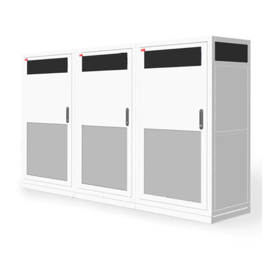
HVC‐PD E‐Bus Charger Installation Guide 2.1.4. Power Cabinet Outside view of the Power Cabinet Base cover 3G Antenna Air outlet Air inlets (also on the left and back side) Door Door handle / lock Inside view of the Power Cabinet AC Fuses Data/communication connection AC Power connection Display (only present in HVC 150) Guidance plate of the cables... -
Page 18: Acs Control Module
HVC‐PD E‐Bus Charger Installation Guide 2.1.5. ACS Control Module Outside view of the ACS Control Module Door Locks WiFi coax connector In- and outputs for cables from Power Cabinet and to pantograph In- and outputs DC power cables Inside view of the ACS Control Module Communication connection Connection block Protection cover for DC contactors... -
Page 19: Junction Box
HVC‐PD E‐Bus Charger Installation Guide 2.1.6. Junction Box Outside view Junction Box Cover In- and outputs DC power cables Output DC- OVP sensing cable 2.1.7. Charge pole Outside view Charge pole Door Emergency button (EMO) Charge state indicator light with light sensor (beacon) Pantograph (installation specific) WiFi communication unit RFID unit (optional) Document: V1.2 / Document No.: 6AGA000008-0629-EN | Date: 06-30-2022... -
Page 20: Accessories
Collector head 2.2. Accessories The following parts can be ordered at the time of the initial order or afterwards. Contact ABB Sales department (see Contact information on Page 14 for contact details). 2.2.1. Foundation for Power Cabinet (for reference only) -
Page 21: Foundation For Charge Pole Construction
The concrete foundation can be used to install the Charge pole construction on soil. NOTICE No charge pole foundation in NA. Designs are available in Appendix G and must be manufactured by installer, not manufactured by ABB. Base plate Counter weights Document: V1.2 / Document No.: 6AGA000008-0629-EN | Date: 06-30-2022... -
Page 22: Communication Glass Fiber Cable
) connectors for each cable. If glass fiber cable is not supplied by ABB, then gland dimensions listed in section Gland layout of the ACS Control Module on Page 106 must be followed. Please note that special precautions should be taken, so that prefabricated fiber optic cable will pass through the gland (for example order cable with M32 gland assembled on it). -
Page 23: Rfid Unit
HVC‐PD E‐Bus Charger Installation Guide 2.2.4. RFID unit Needed when multiple Charge Poles are installed close to each other (distance between each other is lower than 12 m). Amount Part number Description RFU 630-131xx RFID RFU63x (Sick) SSL-2J04-G10ME (part RFID Ethernet cable 10 m (male connector, M12, 4-pin, straight, 6030928) D-coded / male connector, RJ45, 8-pin, straight) (Sick) 2070427... -
Page 24: Project Planning
The different phases of the full project plan are shown in the figure below: A. Preparation The owner / site operator has ordered a HVC-PD E-Bus Charger. In this phase all preparation work must be done before the contractor can do the civil and electrical works. -
Page 25: Preparation
The contractor is responsible for all construction documentation of the site, among other things: drawings, calculations, certifications, licenses and test reports. The location of the HVC-PD E-Bus Charger must be chosen. See section Location on Page 27 and section Geometry of infrastructure on Page 28. -
Page 26: Permits
HVC‐PD E‐Bus Charger Installation Guide 3.2. Permits The installation of a HVC-PD E-Bus Charger will require a number of permits, depending on national and local laws. This section lists a number of points of attention. 3.2.1. Power connection The HVC-PD E-Bus Charger requires high current: ... -
Page 27: Upgrade Grid
HVC‐PD E‐Bus Charger Installation Guide 3.3. Upgrade grid The HVC-PD E-Bus Charger can be connected directly to the electrical grid or to an existing customer low voltage power distribution cabinet. In both cases a 198 A, 480/277 V AC or for the Canada version a 168 A, 600/347 V AC, 60 Hz, 3P+GND connection to each Power Cabinet (HVC 150 or HVC 150S) is required. -
Page 28: Geometry Of Infrastructure
HVC‐PD E‐Bus Charger Installation Guide Design and arrange the location around the HVC-PD E-Bus Charger on a matter that the Charge Pole and the Power Cabinet are hit by a vehicle is as small as possible. For example, there can be installed bollards (see picture below). -
Page 29: Placement Of Multiple Cabinets
HVC‐PD E‐Bus Charger Installation Guide The HVC 150(S) has air inlets (A) on all sides and air outlet (B) on the front to control the temperature inside the cabinet. Do not install any objects near these air inlets and outlets (see also Caution above). If necessary, take precautions to prevent snow, sand or dust from blocking the inlets and outlets. -
Page 30: Required Space For The Charge Pole
HVC‐PD E‐Bus Charger Installation Guide When placing multiple HVC 150 systems, it is necessary to take the following into account: Cabinets can be placed side-by-side; Cabinets can be placed back-to-back with 7.87 Inch distance (2x 3.94 Inch) or when the sides are free with 0 Inch distance; ... -
Page 31: Pole Position In Relation To The Bus
NOTICE Before ordering the Charge pole the correct position of the pantograph within the pole must be calculated by ABB. This is determined during the site survey for placement of the pole and is performed by ABB. Contact ABB Sales department (see Contact information on Page 14 for contact details). -
Page 32: Pole Position In Relation To The Drive Direction Of The Bus
HVC‐PD E‐Bus Charger Installation Guide 3.6.1. Pole position in relation to the drive direction of the bus Note: the following example is with respect to a bus which has the contact rails directly above the front wheelbase. The front wheelbase is exactly below the contact rails on the roof of the bus. So the center of the pole should be in line with the center of the front wheel of the bus. - Page 33 The pole can be placed on the left side or on the right side (driver side) of the bus. This must be communicated with ABB before ordering the Charge Pole. This will also be noted by ABB during the site survey for the placement of the pole. Contact ABB Sales department (see Contact information on Page 14 for contact details).
-
Page 34: Maximum Slope Of The Road In X-Axis
HVC‐PD E‐Bus Charger Installation Guide 3.6.3. Maximum slope of the road in X-axis The maximum slope of the road sideways direction is 3.5⁰, including the kneeling of the bus. This will shift the top of the bus 7.87 Inch relative to the center of the bus. So the displacement caused by the road angle should be taken into account calculating the position of the Charge Pole with respect to the bus. -
Page 35: Maximum Slope Of The Road In Z-Axis
NOTICE The road inclination should be known before the pole is installed on the location. This will also be noted by ABB during the site survey for the placement of the pole. Contact ABB Sales department (see Contact information on Page 14 for contact details). -
Page 36: Electrical Engineering
HVC‐PD E‐Bus Charger Installation Guide 3.7. Electrical engineering 3.7.1. Electrical installation The electrical installation must be completed according to the local safety and electrical regulations and laws. See section Upgrade grid on Page 27 for the requirements of the electrical connection. A one line diagram for the electrical connection is shown in the figure that follows. -
Page 37: Lightning Protection
One electrode (ground rod) of maximum 10 Ω must be placed into the earth near the pole foundation. In some cases also additional grounding is required at the Power Cabinet side. This requirement must be determined by the contractor and owner of the site / HVC-PD E-Bus Charger. -
Page 38: Construction
4. Construction 4.1. About construction The construction phase includes all work required to prepare the location and make it ready for the placement and connection of the HVC-PD E-Bus Charger. The construction phase can start when: All engineering work is done. -
Page 39: Construct Foundation Of The Power Cabinet
HVC‐PD E‐Bus Charger Installation Guide Transport Arrangement for the delivery of the HVC-PD E-Bus Charger with the ABB Delivery department. See Contact information on Page 14 for contact details. The delivery time is at least four months. 4.2. Construct foundation of the Power Cabinet 4.2.1. -
Page 40: Workflow With Concrete Foundation
HVC‐PD E‐Bus Charger Installation Guide 4.2.2. Workflow with concrete foundation NOTICE Concrete foundation should be designed by the customer. ABB does not sell concrete foundation. For detail drawings see Appendix E Dimensions concrete foundation Power Cabinet. WARNING Make sure that personnel cannot be crushed or become trapped while moving the foundation. - Page 41 HVC‐PD E‐Bus Charger Installation Guide The conduits must be installed with a curve inside the foundation in order to prevent water from entering the conduits, and seal the space between the conduits and all open holes. 10. Route the AC power cable through one of the eight holes (B). Make sure that a cable length of 39.37 Inch is available above the surface of the foundation for internal routing in the cabinet.
-
Page 42: Workflow With Metal Frame Foundation
HVC‐PD E‐Bus Charger Installation Guide 4.2.3. Workflow with metal frame foundation 4.2.3.1. HPC175-HVC150 MET FOUND KIN 8IN – NAM (2CEB489802R0001) Place the frame (A) in the desired position and mark the position of the holes for drilling. Remove the frame. Drill and tap holes at the marked positions. The holes must be suitable for bolt size M16. Route the cables tray through one of the cable openings (B). -
Page 43: Workflow Mounting Power Cabinet Direct On A Floor (Footprint)
HVC‐PD E‐Bus Charger Installation Guide 4.2.4. Workflow mounting Power Cabinet direct on a floor (footprint) Drill and tap holes in the floor at the indicated positions (A). The holes must be suitable for bolt size M16. Make rectangular holes on the indicated positions (B) and (C). For detail drawings bottom view of Power Cabinet see Appendix A Dimensions Power Cabinet. -
Page 44: Construct Foundation Of The Charge Pole (For Reference Only)
Use a tube foundation to get a firm fixation on soil. This tube foundation can be used if there are space restrictions, for example close to a building. Contact the ABB Sales department for more information and possibilities, see Contact information on Page 14 for contact details. - Page 45 100 kPa, no soil compact actions has to be taken. If the concrete foundation will be installed on another ground type than sand (like rock, gravel, clay or peat), take contact with the ABB Sales department, see Contact information on Page 14 for contact details.
- Page 46 HVC‐PD E‐Bus Charger Installation Guide Installing the concrete base plate Preconditions: 4x WLL 3/5.0 tons lifting claws (are not delivered by ABB, use for example Starcon Universal Lifting Claws, art.no. 99.11590082B). WARNING Make sure that personnel cannot be crushed or become trapped while moving the foundation.
- Page 47 Installing the counter weights Preconditions: 2x WLL 1.5/2.5 tons lifting claws (are not delivered by ABB, use for example Starcon Universal Lifting Claws, art.no. 99.11590081B). With the concrete base plate in position the counter weights can be installed. These counter weights are needed to keep the charging pole construction up right during extreme weather conditions and to prevent the construction from tilting.
- Page 48 HVC‐PD E‐Bus Charger Installation Guide Compaction the soil around the concrete foundation Before filling the gap around the concrete foundation ensure that all: Conduits are installed to the concrete base plate. The conduits must come out of the holes on the top side of the concrete base plate with a length of about 9.84 inch.
-
Page 49: Cabling
4.4. Cabling 4.4.1. Charge system configuration Overview electrical connections of a HVC-PD 150 kW charge system Document: V1.2 / Document No.: 6AGA000008-0629-EN | Date: 06-30-2022 Page 49 of 146... - Page 50 (Secondary) (Secondary) Overview electrical connections of a HVC-PD 450 kW charge system Separated electrical diagrams for the different HVC-PD Charge systems are available (Ask associated PM or sales representative if required): 6AGA000008-0617, Electrical diagram HVC-PD 150 kW E-Bus Charger, ...
-
Page 51: Ac Power Cable
HVC‐PD E‐Bus Charger Installation Guide 6AGA000008-0619, Electrical diagram HVC-PD 450 kW E-Bus Charger. Contact ABB Sales department (see Contact information on Page 14 for contact details) to request the electrical diagrams. 4.4.2. AC power cable Cable type: 3P+GND (optional shielded). The cable shielding (if present) must be attached to the GND Rail at both ends of the cable. -
Page 52: Cable Specification List
HVC‐PD E‐Bus Charger Installation Guide 4.4.5. Cable specification list Tables below provides general specifications for the needed cables. Use these tables to select cables, taking into account local installation conditions, cable length, cable temperature rating, losses and local regulations. AC and DC power cables Functional description DC Power cable GND cable... -
Page 53: Internet Connection
If the internet connection to the HVC-PD E-Bus Charger is missing, the product warranty and/or ABB’s service level agreement (SLA) may severely impact or even void. -
Page 54: Placement And Connection
HVC‐PD E‐Bus Charger Installation Guide 5. Placement and Connection 5.1. About placement and connection When the construction phase is finished, the HVC-PD E-Bus Charger can be placed and connected. The planning steps for the placement and connection phase are shown in the figure below. -
Page 55: Route The Cables
HVC‐PD E‐Bus Charger Installation Guide 5.2. Route the cables Unpack the cables. See Cabling on Page 49 for details which cables must be used. Route the DC power cables through cable conduit. Route the AC utility power, GND wire and Interlock cable through cable conduit. Route the communication glass fiber cable through cable conduit. - Page 56 HVC‐PD E‐Bus Charger Installation Guide The product is delivered by a transport company at the confirmed date of delivery. Make sure that the Power Cabinet has not been shaken or tilted over 30⁰. Document: V1.2 / Document No.: 6AGA000008-0629-EN | Date: 06-30-2022 Page 56 of 146...
-
Page 57: Remove Packaging
HVC‐PD E‐Bus Charger Installation Guide 5.3.2. Remove packaging Preconditions Tools: spanner (size 24). Remove the packaging material from the Power Cabinet. Remove the bag which contain the keys, cover caps and mounting material that are attached with tape on one of the lifting eyebolt at the top of the cabinet. Keep this bag with parts in a safe place. -
Page 58: Move Cabinet With A Hoist
HVC‐PD E‐Bus Charger Installation Guide DANGER Make sure that the main switch of the power supply group for the product is set to the OFF position. Do a voltage check to make sure that the electrical power is disconnected from the system. Secure against resetting. -
Page 59: Move Cabinet With A Forklift Truck
HVC‐PD E‐Bus Charger Installation Guide Insert the bolts (A) or (B) into the holes at the opposite corners of the cabinet, if not placed upon delivery. Tighten the bolts. Connect the hoisting equipment (C). CAUTION Keep the hoisting angle below 60⁰. Move the Power Cabinet to the foundation. 5.4.2. -
Page 60: Install Power Cabinet Onto The Foundation
HVC‐PD E‐Bus Charger Installation Guide 5.5. Install Power Cabinet onto the foundation 5.5.1. Connect Power Cabinet to foundation Preconditions: Tools: spanner (size 24). Cover caps (4x) that were removed from the Power Cabinet (bag with parts). The Power Cabinet is about 19.69 Inch above its location. DANGER Make sure that the main switch of the power supply group for the product is set to the OFF position. - Page 61 HVC‐PD E‐Bus Charger Installation Guide Placement on metal frame foundation Foundation Power Cabinet Tapped holes Carefully lower the Power Cabinet (B) onto the foundation (A). Make sure that you do not trap the cables (C). Make sure that the cabinet is aligned with the tapped holes (D). Insert the M16 bolts (A) fitted with the washers into the holes in the corners (4x).
-
Page 62: Open The Door Of The Power Cabinet
HVC‐PD E‐Bus Charger Installation Guide Remove the swivel eye bolts or lifting loops (A). Place the cover caps (B) in the holes (4x). 5.5.2. Open the door of the Power Cabinet Preconditions: Key that were removed from the Power Cabinet (bag with parts). Unlock the handle (B) Use the handle (B) to open the door (A). -
Page 63: Move The Sliding Plate Of The Guidance Plates Of The Cabinet
HVC‐PD E‐Bus Charger Installation Guide 5.5.3. Move the sliding plate of the guidance plates of the cabinet Preconditions: Tools: spanner (size 13). Loosen the bolts (A). Move the sliding plate (B) of the 2 guidance plates. 5.5.4. Route cables through guidance plates Route the cables (A) through the right guidance plates (B). Make sure that there is sufficient cable length to reach the connectors at the top of the cabinet. -
Page 64: Move Sliding Plates Of The Guidance Plates Of The Cabinet
HVC‐PD E‐Bus Charger Installation Guide NOTICE A length of 118.11 Inch is required, because the connection of the cables with the connectors in the Power Cabinet is at the middle of the cabinet. 5.5.5. Move sliding plates of the guidance plates of the cabinet Preconditions: ... -
Page 65: Install Border Covers Of The Power Cabinet
HVC‐PD E‐Bus Charger Installation Guide 5.5.6. Install border covers of the Power Cabinet Preconditions: Tools: torx screwdriver (size 2163TX-T30). M5 bolts (8x) that were removed from the Power Cabinet (bag with parts). Put the front cover (A) against the bottom front of the Power Cabinet by aligning the four bolts at the back side of the front cover (A) with the holes in the bottom front. -
Page 66: Connect Ac Power Cable And Gnd Wires Power Cabinets
HVC‐PD E‐Bus Charger Installation Guide Put the front border cover (A) against the front of the Power Cabinet. Put the rear border cover (B) against the rear of the Power Cabinet. Put the side border covers (D) against the sides of the Power Cabinet. Insert the M5 bolts (C) into the holes (8x). -
Page 67: Connect The Gnd Wire Of The Ac Power Cable
HVC‐PD E‐Bus Charger Installation Guide Remove the 3 protection covers (D) from the connector blocks (C). Put the protection covers in a safe location as it will be installed again later on. 5.6.2. Connect the GND wire of the AC power cable Preconditions: Tools: wire cutter, wire stripper pliers, cable lug, spanner (size 19), torque wrench (size 19). -
Page 68: Connect The Ac Power Cable
HVC‐PD E‐Bus Charger Installation Guide Make a loop in the GND wire. NOTICE For safety, it is recommended to make a loop in the GND wire so it is longer than the phase wires. This loop makes sure that the GND wire is not the first wire that is disconnected if the Power Cabinet is moved by a collision. - Page 69 HVC‐PD E‐Bus Charger Installation Guide Cut the wires of the AC power cable to the correct lengths to reach the connectors. Do not make the wire routing too tight, or too loose. Strip the insulation on the required length specified by the used lug from the end of the wire (B).
-
Page 70: Install The Protection Covers
HVC‐PD E‐Bus Charger Installation Guide 5.6.4. Install the protection covers Preconditions: Tools: cross-head screwdriver Take the 3 protection covers that was removed in Remove the protection covers on Page Place the protection covers (D) back on the connector blocks (C). Take the protection plate and the screws that were removed in Remove the protection covers on Page 66. -
Page 71: Install Lightning Protection (Optional)
Leave the main switch switched off. The Power Cabinet is not ready for use yet. If there is no appointment for commissioning yet, contact the ABB Delivery department to make an appointment for commissioning. See Contact information on Page 14 for contact details. -
Page 72: Connect The Gnd Wire To The Charge Pole
HVC‐PD E‐Bus Charger Installation Guide 5.6.6. Connect the GND wire to the Charge pole NOTICE The GND wire to the Charge pole is only connected within the HVC 150 Power Cabinet, see for more details section Cabling on Page 49. Preconditions: Tools: wire cutter, wire stripper pliers, cable lug, spanner (size 19), torque wrench (size 19). -
Page 73: Connect The Gnd Wire Between The Power Cabinets
HVC‐PD E‐Bus Charger Installation Guide 5.6.7. Connect the GND wire between the Power Cabinets Preconditions: Tools: wire cutter, wire stripper pliers, cable lug, spanner (size 19), torque wrench (size 19). Both GND wire connection must be made between the HVC 150 and the first HVC 150S and between both HVC 150S, see also section Cabling on Page 49: Cut the GND wire of the power cable to the correct length to reach the GND rail. -
Page 74: Connect The Dc Power Cables
HVC‐PD E‐Bus Charger Installation Guide Remove the protection cover Remove the protection plate (A) by loosening the screws (B) (4x). Put the protection plate and screws in a safe location as it will be installed again later on. 5.7.1. Connect the DC power cables Cut the wires of the DC power cable to the correct lengths to reach the connectors. -
Page 75: Install The Protection Cover
HVC‐PD E‐Bus Charger Installation Guide 5.7.2. Install the protection cover Take the protection plate that was removed in Remove the protection covers on Page 74. Place the protection plate (A) back over the DC connector blocks and secure the plate by the screws (B) (4x). 5.8. -
Page 76: Connect The Ac Utility Power Cable
HVC‐PD E‐Bus Charger Installation Guide Preferred cable route Route the AC utility cable to the terminal block (A). Refer to the figure for the preferred cable route inside the cabinet (only within the HVC 150). Route the Interlock cable(s) to the terminal block (B). Refer to the figure for the preferred cable route inside the cabinet. -
Page 77: Connect The Interlock Cable For The Hvc 150 Kw System
HVC‐PD E‐Bus Charger Installation Guide 5.8.3. Connect the Interlock cable for the HVC 150 kW system Interlock cable connection in the primary HVC 150: Terminal block Interlock cable from/to ACS Control Module (ACM) Move the cable towards the terminal block (A). Strip 0.43 Inch of the insulation from the ends of only the White and Brown wire! Crimp a ferrule onto the end of the White and Brown wire. -
Page 78: Upgrade The Interlock Connection To The Hvc 300 Kw System
HVC‐PD E‐Bus Charger Installation Guide 5.8.4. Upgrade the Interlock connection to the HVC 300 kW system Interlock cable connection in the primary HVC 150: Terminal block Interlock cable from/to ACS Control Module (ACM) Interlock cable from/to secondary 1 HVC 150S Move the cables towards the terminal block (A). Strip 0.43 Inch of the insulation from the ends of only the White and Brown wire! Crimp a ferrule onto the end of the White and Brown wire. - Page 79 HVC‐PD E‐Bus Charger Installation Guide Interlock cable connection in secondary 1 HVC 150S: Terminal block Interlock cable from/to primary HVC 150 Move the cables towards the terminal block (A). Strip 0.43 inch of the insulation from the ends of only the White and Brown wire! Crimp a ferrule onto the end of the White and Brown wire.
-
Page 80: Upgrade The Interlock Connection To The Hvc 450 Kw System
HVC‐PD E‐Bus Charger Installation Guide 5.8.5. Upgrade the Interlock connection to the HVC 450 kW system Interlock cable connection in secondary 1 HVC 150S: Terminal block Interlock cable from/to primary HVC 150 Interlock cable from/to secondary HVC 150S Interlock cable from/to secondary HVC 150S Move the cables towards the terminal block (A). - Page 81 HVC‐PD E‐Bus Charger Installation Guide Tighten the connector screws with a tightening torque of 1.0 ft-lb. Interlock cable connection in secondary 2 HVC 150S: Terminal block Interlock cable from/to secondary 1 HVC 150S Move the cables towards the terminal block (A). Strip 0.43 Inch of the insulation from the ends of only the White and Brown wire! Crimp a ferrule onto the end of the White and Brown wire.
-
Page 82: Connect The Can Cable
HVC‐PD E‐Bus Charger Installation Guide 5.8.6. Connect the CAN cable NOTICE The CAN cable connection is only needed for the HVC 300 kW and 450 kW E-Bus Charger, see for more details section Cabling on Page 49. CAN cable connection in secondary 2 HVC 150S (in case of a HVC 450 kW system): Terminal block CAN cable to secondary 1 HVC 150S Move the cable towards the terminal block (A). - Page 83 HVC‐PD E‐Bus Charger Installation Guide CAN cable connection in secondary 1 HVC 150S: Terminal block CAN cable to primary HVC 150 CAN cable from secondary 2 HVC 150S (in case of a HVC 450 kW system) Move the cable towards the terminal block (A). Strip 0.43 Inch of the insulation from the ends of the wires.
- Page 84 HVC‐PD E‐Bus Charger Installation Guide CAN cable connection in primary HVC 150: Terminal block CAN cable from secondary 1 HVC 150S Move the cable towards the terminal block (A). Strip 0.43 Inch of the insulation from the ends of the wires. Crimp a ferrule onto the end of the wire. Loosen the connector screws.
-
Page 85: Connect The Communication Cable Power Cabinet
HVC‐PD E‐Bus Charger Installation Guide 5.9. Connect the communication cable Power Cabinet NOTICE The communication fiber cables to the ACS Control Module are only connected within the primary HVC 150 Power Cabinet, see for more details section Cabling on Page 49. 5.9.1. Route the cable to the terminal blocks Preferred cable route Route the communication fiber cable to module D1 (B) and D2 (A). -
Page 86: Close The Door Of The Power Cabinet
HVC‐PD E‐Bus Charger Installation Guide Remove the protection covers from the optical connectors. Connect the two Ethernet fiber cables (C) onto the module D2 (A): Rx with Td D2; Tx with Rd D2. Connect the two CAN bus fiber cables (D) onto module D1 (B): ... -
Page 87: Unpack The Charge Pole
Make sure that the painted seal on the pantograph electrical connectors are not damaged. Is this not the case, contact ABB Delivery department (see Contact information on Page 14 for contact details). Document: V1.2 / Document No.: 6AGA000008-0629-EN | Date: 06-30-2022... -
Page 88: Remove Packaging
HVC‐PD E‐Bus Charger Installation Guide 5.11.2. Remove packaging Remove the packing foil from the Charge Pole (if present). Open the top side of the wooden box with the plate work. Keep the bag with bolts and nuts to assemble the pole in a safe place. 5.12. - Page 89 HVC‐PD E‐Bus Charger Installation Guide Connect the hoisting equipment to the lifting points on the Charge Pole. Lift the Charge Pole by using slings and place the Charge Pole beside the trailer. In order not to damage the Charge Pole, use a wooden beam (A) on which the end of the pole can rest.
-
Page 90: Install Charge Pole Onto The Foundation
HVC‐PD E‐Bus Charger Installation Guide Move the Charge Pole to the foundation. 5.13. Install Charge Pole onto the foundation Preconditions: Tools: mobile elevated work platform, spanner (size 36), torque wrench (size 36). DANGER Make sure that the main switch of the power supply group for the product is set to the OFF position. - Page 91 HVC‐PD E‐Bus Charger Installation Guide It is possible to choose to lubricate the bolts first or not with copper fat. NOTICE There are a number of reasons for using copper fat: It is corrosion resistant; Less torque must be used on the nut to develop the same force on the bolt.
-
Page 92: Install Mast Boom Onto Column
Be aware that the correct height to the bottom side of the foot print of the vertical frame relative to the ground level of the top of road (= charging position of the bus) must be calculated by ABB. Contact ABB Sales department (see Contact information on Page 14 for contact details). - Page 93 HVC‐PD E‐Bus Charger Installation Guide Remove the bolts (D) and nuts (E) (2x) which secured the transport holder (A) with the column (C) of the Charge Pole. Lift up the mast boom (B) until it touches the column (C) horizontally. Mount the mast boom (B) onto the column (C) by using 12x M16 bolt + washer / washer + nut connection.
- Page 94 HVC‐PD E‐Bus Charger Installation Guide Release the slings from the transport holder (A). Remove the transport holder (A) from the mast boom (B) by removing the bolts (G) and washers (F) (4x). Remove on both side the U-profiles (I) by detaching the two M6 bolts (J). Remove the cover plate (H) by detaching the M6 bolts (J).
- Page 95 HVC‐PD E‐Bus Charger Installation Guide NOTICE To make it easier to place the bottom corner cover plates (L), the hinge plates on both sides of the columns of the Charge Pole can be removed. This makes it possible that the cover plate (H) does not have to be removed.
- Page 96 HVC‐PD E‐Bus Charger Installation Guide 17. Place back the cover plate (H) and tighten the M6 bolts (J) (4x). 18. Place back the U-profiles (I) on both side, and tighten the M6 bolts (J) (4x). Document: V1.2 / Document No.: 6AGA000008-0629-EN | Date: 06-30-2022 Page 96 of 146...
-
Page 97: Pantograph Adjustment
HVC‐PD E‐Bus Charger Installation Guide 5.15. Pantograph adjustment WARNING Make sure that personnel cannot be falling from the platform when working at height. CAUTION Remove the ty-raps that secure the cables to the Pantograph from the cable hooks located near the Pantograph. Check whether the cables are stuck anywhere or can catch on something before the Pantograph is shifted. - Page 98 HVC‐PD E‐Bus Charger Installation Guide POLE ON THE RIGHT ‐ DRIVERS POINT OF VIEW Inclination + Kneeling (Angles in degrees) 740.75 ‐0.5 ‐1 ‐1.5 ‐2 ‐2.5 ‐3 ‐3.5 1569 1541 1513 1484 1456 1428 1400 1372 1344 1315 1287 1259 1231 1203 1175 1519 1491 1463 1434 1406 1378 1350 1322 1294 1265 1237 1209 1181 1153 1125 1469 1441...
- Page 99 HVC‐PD E‐Bus Charger Installation Guide POLE ON THE LEFT ‐ DRIVERS POINT OF VIEW Inclination + Kneeling (Angles in degrees) 987.25 ‐0.5 ‐1 ‐1.5 ‐2 ‐2.5 ‐3 ‐3.5 1759 1787 1815 1844 1872 1900 1928 1956 1984 2013 2041 2069 2097 2125 2153 1709 1737 1765 1794 1822 1850 1878 1906 1934 1963 1991 2019 2047 2075 2103 1659 1687...
-
Page 100: Pantograph Setting Range Adjustment
HVC‐PD E‐Bus Charger Installation Guide 5.15.2. Pantograph setting range adjustment Determine how many cover plates (B) should be removed around the pantograph (C). If no cover plates need be removed, go to step 5. Remove on both side the U-profiles (A) by detaching the two M6 bolts. Remove the cover plates (B) by detaching the M6 bolts. - Page 101 HVC‐PD E‐Bus Charger Installation Guide Place the pantograph in the correct position, see also section Instruction for pantograph adjustment and alignment on Page 97, by moving the pantograph over the C-profile (by hand or with help of the present tensioning straps). Lock the pantograph by tighten the M12 bolts (D) (4x) of the clamping plates (E). NOTICE The tensioning straps must not be removed after the pantograph has been adjusted.
-
Page 102: Pantograph Z-Axis Angle Adjustment
HVC‐PD E‐Bus Charger Installation Guide 5.15.3. Pantograph Z-axis angle adjustment The pantograph can be adjust for road inclination (Z-axis) between the 0º and 6.0º, see also section Maximum slope of the road in Z-axis on Page 35. The angle setting of the pantograph is done by twisting the pantograph over its suspension system. -
Page 103: Pantograph X-Axis Angel Adjustment
HVC‐PD E‐Bus Charger Installation Guide 5.15.4. Pantograph X-axis angel adjustment The pantograph can be adjust at respect to the slope of the road in sideway direction (X-axis) between -6.0º to 6.0º in steps of 1.5º, see also section Maximum slope of the road in X-axis on Page 34. - Page 104 HVC‐PD E‐Bus Charger Installation Guide Open the door (A) of the Charge Pole by unlocking the two lockers (B). Steps 2 to 4 are only required when the lower front cover plate is delivered assembled onto the pole. Normally the lower front cover plate (E) and both U-profiles (C) are delivered separately with the pole.
-
Page 105: Connect Gnd Wires Of The Power Cabinet
HVC‐PD E‐Bus Charger Installation Guide 5.16.2. Connect GND wires of the Power Cabinet Preconditions: Tools: wire cutter, wire stripper pliers, cable lug, spanner (size 13), torque wrench (size 13). Cut the GND wire to the correct length to reach the GND rail. Do not make the wire routing too tight, or too loose. -
Page 106: Gland Layout Of The Acs Control Module
HVC‐PD E‐Bus Charger Installation Guide Screw at the back side of the lighting protection connection a toothed washer (D) and a nut (F) on the bolt (C). Tighten the bolt with a tightening torque of 11 ft-lb. 5.16.4. Gland layout of the ACS Control Module Gland # Clamping range ØF Cable... -
Page 107: Open The Door Of The Acs Control Module
HVC‐PD E‐Bus Charger Installation Guide 5.16.5. Open the door of the ACS Control Module Preconditions: Unlock the locks (B). Open the door (A). 5.16.6. Connect the DC+ power input cables Preconditions: Tools: wire cutter, wire stripper pliers, cable lugs (3x), spanner (size18), torque wrench (size 18). - Page 108 HVC‐PD E‐Bus Charger Installation Guide Remove the DC contactor’s protection cover. Loosen and remove the cable gland’s (#14, #15 and #20) nuts, including the cover caps inside the gland, for the DC+ power cables. Slide the cable gland’s nuts over the DC power cables. Strip the insulation on the required length specified by the used lug from the end of the wire (B).
-
Page 109: Connect The Dc- Power Input Cables In Junction Box
HVC‐PD E‐Bus Charger Installation Guide NOTICE Make sure that the sense wires are placed back on the DC contactor connectors. If this is not the case, then the system will not function. 13. Tighten the nuts (C) with a tightening torque of 22 ft-lb. 14. - Page 110 HVC‐PD E‐Bus Charger Installation Guide Loosen and remove the cable gland’s (#03 - #05) nuts for the DC power cables. Slide the cable gland’s nuts over the DC power cables. Strip the insulation on the required length specified by the used lug from the end of the DC power cables.
-
Page 111: Connect The Ac Utility Power Cable From Power Cabinet
HVC‐PD E‐Bus Charger Installation Guide 16. Tighten the screws (C) (6x) to secure the Junction Box. 5.16.8. Connect the AC utility power cable from Power Cabinet Preconditions: Tools: wire cutter, wire stripper pliers, screwdriver, ferrules, crimp pliers. Loosen and remove the cable gland’s (#1) nut for the AC utility power cable. Slide the cable gland’s nut over the AC utility power cable. -
Page 112: Connect The Communication Cable From The Power Cabinet
HVC‐PD E‐Bus Charger Installation Guide 5.16.9. Connect the communication cable from the Power Cabinet Route the communication fiber cables to module U5 (A) and U7 (B). Remove the protection covers from the optical connectors. Connect the two Ethernet fiber cables (C) onto module (A): ... -
Page 113: Connect The Rfid Cables
HVC‐PD E‐Bus Charger Installation Guide Route the WiFi cable (A) to the WiFi connector (B). Insert the WiFi type N-plug into the WiFi connector (B). Hand tighten the WiFi plug. 5.16.11. Connect the RFID cables NOTICE This section is not required if the RFID module is not present. Preconditions: ... -
Page 114: Connect The Interlock Cable From The Power Cabinet
HVC‐PD E‐Bus Charger Installation Guide Route the RFID Power cable (C) through gland #10 to connector block X4, with sufficient cable length (do not make the cable routing too tight, or too loose). Tighten the nut of the gland to secure the RFID Power cable. Strip the insulation from the cable. -
Page 115: Connect The Other Cables To The Acs Control Module
HVC‐PD E‐Bus Charger Installation Guide Loosen and remove the cable gland’s (#3) nut for the Interlock cable. Slide the cable gland’s nut over the Interlock cable. Route the cables through the gland to the connector blocks (A), with sufficient cable length (do not make the cable routing too tight, or too loose). Tighten the nuts of the gland to secure the Interlock cable. - Page 116 HVC‐PD E‐Bus Charger Installation Guide Overview of the terminal block Pantograph heater cable EMO cable Interlock cable Beacon cable Pantograph CP/PE cable Distance sensor cable ACS Control cable Loosen and remove the cable gland’s nuts (see for overview Gland layout of the ACS Control Module in Page 106) for the cables. Slide the cable gland’s nut over the cables.
- Page 117 HVC‐PD E‐Bus Charger Installation Guide Pantograph heater cable Wire 1 ACS L Heater Wire 2 ACS N Heater GND (green/yellow) Interlock / DC Guard cable Shield White Interlock In Brown Interlock Out DC_Guard_A DC_Guard_GND Next Interlock / next DC Guard cable (only for sequential mode) Next_Interlock_In Next_Interlock_Out Next_DC_Guard_A...
-
Page 118: Close The Door Of The Acs Control Module
HVC‐PD E‐Bus Charger Installation Guide 5.16.14. Close the door of the ACS Control Module Preconditions: Close the door (A). Close the locks (B). 5.16.15. Place back cover plate and close door of the Charge Pole Preconditions: Key. A minimum of two persons is required. ... -
Page 119: Install Cover Plates
HVC‐PD E‐Bus Charger Installation Guide Close the door (A) of the Charge Pole Locking the two lockers (B). 5.17. Install cover plates Preconditions: Packing foil are removed from the plate work. Tools: torx screwdriver (size 2163TX-T30). Put the two U-profile cover plates (B) against the bottom of the column (A). Insert the M6 bolts (C) into the holes (4x). -
Page 120: Grouting Of The Pole Construction
HVC‐PD E‐Bus Charger Installation Guide 5.18. Grouting of the pole construction Preconditions: All construction work on the pole is completed. The Site Acceptance Test (SAT) is completed. Tools: non-shrink pour mortar (recommended Maxit EXM721), mixing tool, bucket or caster. To protect the wire anchors from rusting by means of sealing and to prevent wear of foundation ( foreign objects such as sand, ground, etc entering into cable ducts), the space between the foot print of the vertical frame and the concrete foundation has to be filled with non-shrink grout. -
Page 121: Commissioning
HVC‐PD E‐Bus Charger Installation Guide 6. Commissioning 6.1. Commissioning preparation Commissioning is the last phase necessary to get the HVC-PD E-Bus Charger into operation. The planning steps for the commissioning phase are shown in the figure below. Commissioning The commissioning of the HVC-PD E-Bus Charger need to be performed by a service engineer from the ABB Delivery department and/or a certified local ABB service engineer. -
Page 122: Customer Acceptance Form (Caf)
SAT checklist, list of remaining items. After the CAF has been signed, the customer support will be handled by the ABB Service department. If there are any remaining items, they can be noted on the CAF document, together with the agreed solution and the expected date of completion. -
Page 123: Service And Maintenance
HVC‐PD E‐Bus Charger Installation Guide 7. Service and Maintenance 7.1. About Service and Maintenance Service and Maintenance Maintenance is done according the maintenance schedule. This is outside of the scope of this document. DANGER Any service and maintenance work on pantograph and or charger system has to be only executed on powered-off device. - Page 124 HVC‐PD E‐Bus Charger Installation Guide NOTICE When the HVC-PD E-Bus Charger is exposed to rain, it is sufficient to clean it twice a year. CAUTION Do not apply high-pressure water jets. Water may leak into the Power Cabinet. If a high-pressure water jet has been used, make sure that the inside of the Power Cabinet is dry.
-
Page 125: Technical Specification
HVC‐PD E‐Bus Charger Installation Guide 8. Technical Specification 8.1. Electrical specification complete 150 kW system Input Supply voltage 3-phase: GND, L1, L2, L3 Input voltage range 480/277 V AC ± 10% Input frequency range 600/347 V AC +10%/-15% (Canada version) Input frequency range 60 Hz ± 1% Maximum power dissipation 170 kVA Power factor (cos ᵠ) -
Page 126: Electrical Specification Complete 450 Kw System
HVC‐PD E‐Bus Charger Installation Guide 8.3. Electrical specification complete 450 kW system Input Supply voltage 3-phase: GND, L1, L2, L3 Input voltage range 480/277 V AC ± 10% Input frequency range 600/347 V AC +10%/-15% (Canada version) Input frequency range 60 Hz ± 1% Maximum power dissipation 510 kVA Power factor (cos ᵠ) -
Page 127: Environment
89.5 mph (14 Bft) Storage conditions Indoors, dry CAUTION Warranty Warranty will be considered void when the HVC-PD E-Bus Charger is damaged while badly stored at the customer's location. 8.6. Certifications Certifications for complete system UL 2202 HVC 150: Certificate No. TU 72180445 ACM Certificate No. -
Page 128: Appendix
HVC‐PD E‐Bus Charger Installation Guide 9. Appendix Dimensions power cabinet Dimensions ACS Control Module Dimensions Junction Box Dimensions Charge pole Clearance and vertical working range of the pantograph Dimensions Concrete Foundation Power Cabinet Dimensions Metal Foundation Power Cabinet Dimensions Concrete Foundation Pole Power Cabinet – Outline with Foundation Signal connection diagram Ground overview of the system Document: V1.2 / Document No.: 6AGA000008-0629-EN | Date: 06-30-2022... -
Page 129: Dimensions Powe
HVC‐PD E‐Bus Charger Installation Guide A. Dimensions Power Cabinet All sizes in mm 1 mm = 0.039 Inch Document: V1.2 / Document No.: 6AGA000008-0629-EN | Date: 06-30-2022 Page 129 of 146... - Page 130 HVC‐PD E‐Bus Charger Installation Guide All sizes in mm 1 mm = 0.039 Inch Document: V1.2 / Document No.: 6AGA000008-0629-EN | Date: 06-30-2022 Page 130 of 146...
-
Page 131: Dimensions Acs Control Module
HVC‐PD E‐Bus Charger Installation Guide B. Dimensions ACS Control Module All sizes in mm 1 mm = 0.039 Inch Document: V1.2 / Document No.: 6AGA000008-0629-EN | Date: 06-30-2022 Page 131 of 146... -
Page 132: Dimensions Junction Box
HVC‐PD E‐Bus Charger Installation Guide C. Dimensions Junction Box All sizes in mm 1 mm = 0.039 Inch Document: V1.2 / Document No.: 6AGA000008-0629-EN | Date: 06-30-2022 Page 132 of 146... -
Page 133: Dimensions Charge Pole
HVC‐PD E‐Bus Charger Installation Guide D. Dimensions Charge pole All sizes in mm 1 mm = 0.039 Inch Document: V1.2 / Document No.: 6AGA000008-0629-EN | Date: 06-30-2022 Page 133 of 146... - Page 134 HVC‐PD E‐Bus Charger Installation Guide During transport All sizes in mm 1 mm = 0.039 Inch Document: V1.2 / Document No.: 6AGA000008-0629-EN | Date: 06-30-2022 Page 134 of 146...
-
Page 135: Clearance And Vertical Working Range Of The Pantograph
HVC‐PD E‐Bus Charger Installation Guide E. Clearance and vertical working range of the pantograph Document: V1.2 / Document No.: 6AGA000008-0629-EN | Date: 06-30-2022 Page 135 of 146... -
Page 136: Dimensions Concrete Foundation Power Cabinet
HVC‐PD E‐Bus Charger Installation Guide F. Dimensions Concrete Foundation Power Cabinet All sizes in mm 1 mm = 0.039 Inch Document: V1.2 / Document No.: 6AGA000008-0629-EN | Date: 06-30-2022 Page 136 of 146... - Page 137 HVC‐PD E‐Bus Charger Installation Guide All sizes in mm 1 mm = 0.039 Inch Document: V1.2 / Document No.: 6AGA000008-0629-EN | Date: 06-30-2022 Page 137 of 146...
-
Page 138: Dimensions Metal Foundation Power Cabinet
HVC‐PD E‐Bus Charger Installation Guide G. Dimensions Metal Foundation Power Cabinet HxC power cabinet metal foundation (4EPY420133R1) All sizes in mm 1 mm = 0.039 Inch HPC175-HVC150 MET FOUND KIN 8IN – NAM (2CEB489802R0001) Document: V1.2 / Document No.: 6AGA000008-0629-EN | Date: 06-30-2022 Page 138 of 146... - Page 139 HVC‐PD E‐Bus Charger Installation Guide Document: V1.2 / Document No.: 6AGA000008-0629-EN | Date: 06-30-2022 Page 139 of 146...
-
Page 140: Dimensions Concrete Foundation Pole
HVC‐PD E‐Bus Charger Installation Guide H. Dimensions Concrete Foundation Pole All sizes in mm 1 mm = 0.039 Inch Document: V1.2 / Document No.: 6AGA000008-0629-EN | Date: 06-30-2022 Page 140 of 146... -
Page 141: Power Cabinet - Outline With Foundation
HVC‐PD E‐Bus Charger Installation Guide I. Power Cabinet – Outline with Foundation All sizes in mm 1 mm = 0.039 Inch Document: V1.2 / Document No.: 6AGA000008-0629-EN | Date: 06-30-2022 Page 141 of 146... -
Page 142: Signal
HVC‐PD E‐Bus Charger Installation Guide J. Signal connection diagram For HVC 150 kW system Document: V1.2 / Document No.: 6AGA000008-0629-EN | Date: 06-30-2022 Page 142 of 146... - Page 143 HVC‐PD E‐Bus Charger Installation Guide For HVC 300 kW system Document: V1.2 / Document No.: 6AGA000008-0629-EN | Date: 06-30-2022 Page 143 of 146...
- Page 144 HVC‐PD E‐Bus Charger Installation Guide For HVC 450 kW system Document: V1.2 / Document No.: 6AGA000008-0629-EN | Date: 06-30-2022 Page 144 of 146...
-
Page 145: Ground Overview Of The System
HVC‐PD E‐Bus Charger Installation Guide K. Ground overview of the system Document: V1.2 / Document No.: 6AGA000008-0629-EN | Date: 06-30-2022 Page 145 of 146... - Page 146 HVC‐PD E‐Bus Charger Installation Guide NOTES Document: V1.2 / Document No.: 6AGA000008-0629-EN | Date: 06-30-2022 Page 146 of 146...