Toshiba nv Series User Manual
Type1 light profibus-dp module
Hide thumbs
Also See for nv Series:
- Hardware manual (177 pages) ,
- Instruction manual (148 pages) ,
- Operating instructions (functional manual) (49 pages)

Related Manuals for Toshiba nv Series


Summary of Contents for Toshiba nv Series
- Page 1 6F8C1872 Unified Controller type1 light series PROFIBUS-DP Module PF611A / PF612A User's Manual...
- Page 2 Important Information No patent liability is assumed by Toshiba Infrastructure Systems & Solutions Corporation with respect to use of information, illustrations, circuits, equipment or examples of application in this publication. Toshiba Infrastructure Systems & Solutions Corporation reserves the right to make changes and improvements to this publication and/or related products at any time without notice.
- Page 3 The specific details of instruction are indicated inside or near with pictures or text. Instruction (Note) The description of prohibition, instruction, and warning vary depending on the display on the main unit. Unified Controller nv series type1 light PROFIBUS-DP Module PF611A / PF612A User’s Manual...
- Page 4 Otherwise, accidents may be caused. Mount the PROFIBUS-DP module on to the dedicated base unit. Install the device at a place where...
- Page 5 The emergency stop circuit, interlock circuit, etc. are configured Instruction outside the nv series. If the nv series breaks down or malfunctions, it may cause personal injury or mechanical damage. Unified Controller nv series type1 light PROFIBUS-DP Module PF611A / PF612A User’s Manual...
- Page 6 3. Safety Precautions on Daily Use Warning Do not touch any terminal of the Do not use in case of an abnormal module and unit during temperature increase around or Prohibited energization. inside the device or a failure on the Avoid device Otherwise, electric shock may be...
- Page 7 Prohibited and short circuit the battery Instruction voltage at the module’s power Otherwise, explosion or catching fire terminal may be caused. Otherwise, it may cause electric shock. Unified Controller nv series type1 light PROFIBUS-DP Module PF611A / PF612A User’s Manual...
- Page 8 5. Safety Precautions on Disposal Warning Do not throw lithium batteries into a fire Prohibited There is a risk of explosion. Caution When disposing of lithium batteries, Dispose of the units and modules observe the local regulations or as industrial wastes Instruction Instruction rules...
- Page 9 Disclaimer Toshiba Infrastructure Systems & Solutions Corporation is not liable for any loss caused by earthquake, thunder, wind, flood, fire not our responsibility, action by a third party, other accidents, customer’s intention or negligence, incorrect use, or use under abnormal condition.
- Page 10 Precautions for Use About installation • Do not drop the device and modules, hit them, or give a strong shock on them. Otherwise, failure may be caused. • Use your cellular phone or PHS at least 1m away from the product main unit in operation, transmission cables, and I/O cable.
- Page 11 8. This manual and the separate related materials are intended for persons with general knowledge of control equipment. Contact us for any questions about the contents. Unified Controller nv series type1 light PROFIBUS-DP Module PF611A / PF612A User’s Manual...
- Page 12 nv Series Manuals There are other nv series manuals as follows. • Unified Controller nv Series type1 light Controller Unit User’s Manual -Basic Hardware- (6F8C1497) Describes the type1 light (PUM11/PUM12/PUM14) hardware, their usage, and information necessary to create user programs.
- Page 13 (hereinafter referred to as "PROFIBUS" unless required) module PF611A / PF612A (hereinafter referred to as "PF611A" or "PF612A" unless required) of the Unified Controller nv Series type1 light. To use the device correctly, first read "Safety Precautions" before using. For this product, the repair and replacement due to wear or abrasion will be charged even during the warranty period.
- Page 14 Rules for Notations This section describes the following conventions which will help you to understand this manual. Important: Describes precautions to be observed in order to handle the product correctly. Note: Describes rules to be observed in order to handle the product correctly. Supplementary: Provides supplementary explanations.
-
Page 15: Table Of Contents
PF611A information referenced with MREAD instruction ..... 28 RAS Information PF612A information that can be referenced as I/O connection.... 30 …23 Error Inspection ..................32 Chapter 6 Troubleshooting …31 xiii Unified Controller nv series type1 light PROFIBUS-DP Module PF611A / PF612A User’s Manual... - Page 16 Inspection ....................36 Chapter 7 Maintenance parts ................. 38 Maintenance and Inspection …35 General Specification ................40 Appendix A Transmission Specification..............41 Specifications Module Specification ................42 …39 Limitations ..................... 43 External dimensions ................44 Appendix B Controller Interface DPRAM Memory Map …45 Registering the Module .................
- Page 17 Chapter 1 Introducing Describes each part name, functions, and characteristics of the PF611A / PF612A module. Functions and features of PF611A / PF612A ......2 System Configuration Example ..........3...
-
Page 18: Features Of Pf611A / Pf612A Module
I/O, inter-controller message communication, and instrumentation applications. The PF611A and PF612A supports PROFIBUS-DP, which is the most popular among these. The PROFIBUS-DP module enhances connectability by providing PROFIBUS connection to integrated controllers and unified controller nv series type1 light. The product lineup is as follows: Pet name... -
Page 19: System Configuration Example
Figure 1-1, Figure 1-2, and Figure 1-3 show examples of system configurations using PF611A and PF612A. Figure 1-1 System Configuration Example (1) Figure 1-2 System Configuration Example (2) Unified Controller nv series type1 light PROFIBUS-DP Module PF611A / PF612A User’s Manual... - Page 20 Chapter 1 Introducing Configuration Tool Power Supply FA Computer Scanner PF611A System Expansion PROFIBUS cable PROFIBUS Figure 1-3 System Configuration Example (3) 6F8C1872...
- Page 21 Chapter 2 Name and Function of Module Components Describes the name and functions of each part of the PF611A / PF612A module. External View ................ 6 Name of PF611A Module Components and Parts ....8 Name of PF612A Module Components and Parts ....10 Configurator ................
-
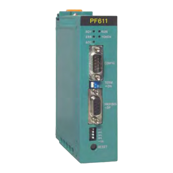
Page 22: External View
Chapter 2 Name and Function of Module Components 2.1 External View Figure 2-1 Appearance of PF611A module 6F8C1872... - Page 23 Figure 2-2 Appearance of PF612A module Unified Controller nv Series type1 light PROFIBUS-DP module PF611A / PF612A User’s Guide...
-
Page 24: Name Of Pf611A Module Components And Parts
Chapter 2 Name and Function of Module Components 2.2 Name of PF611A Module Components and Parts Status LED Configurator port Transmission Mode 2 cable setup switch connector Mode 1 Reset switch setup switch Mode 1 setup switch Figure 2-3 Name of components and parts •... - Page 25 Transmission cable connector (PROFIBUS-DP) PROFIBUS-DP transmission cable connector • Reset switch (RESET) Press when the PF611A is abnormal or when initializing the PF611A independent of the controller. Unified Controller nv Series type1 light PROFIBUS-DP module PF611A / PF612A User’s Guide...
-
Page 26: Name Of Pf612A Module Components And Parts
Chapter 2 Name and Function of Module Components 2.3 Name of PF612A Module Components and Parts Status LED Transmission cable connector Address Mode 2 setup switch setup switch Mode 1 setup switch Reset switch Mode 1 setup switch Figure 2-4 Name of components and parts 6F8C1872... - Page 27 The registered setting of the Mode 1 setup switch and the input/output data size of NetTool should be the same. If they do not match, an error will occur due to the consistency check. Unified Controller nv Series type1 light PROFIBUS-DP module PF611A / PF612A User’s Guide...
- Page 28 Chapter 2 Name and Function of Module Components • Mode 2 setup switch (binary DIP switch) Used to set the action when there is a controller error or transmission error. Set to "OFF" at shipment. Table 2-4 Mode 2 setup switch Mode MD4 MD5 Data update Abnormal Transmit data...
- Page 29 When the reset switch is pressed, the entire module is reset, so the controller may detect an access error on the PF612A and cause an error down. Unified Controller nv Series type1 light PROFIBUS-DP module PF611A / PF612A User’s Guide...
-
Page 30: Configurator
Chapter 2 Name and Function of Module Components 2.4 Configurator The PROFIBUS-DP configurator is used to monitor the PROFIBUS status, read/write cyclic data, and set parameters from a PC. Use the following configurator for PF611A. Name : HMS NetTool for PROFIBUS Version 1.09.0004 or later Manufacturer : HMS INDUSTRIAL NETWORKS AB Supported OS :... - Page 31 Chapter 3 Operation, Function and Setup Describes the operations, functions, and settings related to transmission of the PF611A / PF612A module. Setting ..................16 Cyclic transmission ..............17 Transmission Parameter Setup ..........18 Registration and Setup ............19...
-
Page 32: Setting
Chapter 3 Operation, Function and Setup 3.1 Setting PF611A / PF612 is 1 slot width. Fix to the base unit with the top and bottom lock levers and the top screwed (M4 screw). (1) Module insert in slot guide of base unit. Slot guide (2) Hold the top and bottom of the module, insert vertically on the base unit. -
Page 33: Cyclic Transmission
200h I/O Input Input module Input Input I/O Input Input module Area Area I/O Input Input module PROFIBUS-DP Figure 3-1 Cyclic transmission (Combination of PF611A and I/O) Unified Controller nv series type1 light PROFIBUS-DP Module PF611A / PF612A User’s Manual... -
Page 34: Transmission Parameter Setup
Chapter 3 Operation, Function and Setup Controller Master(PF611A) Slave(PF612A) Controller 100h 200h Input Input Output Output area area area area 200h 100h Output Output Input Input area area area area PROFIBUS-DP Figure 3-2 Cyclic transmission (Combination of PF611A and PF612A) 3.3 Transmission Parameter Setup When using this module, you must set the transmission parameters by the PROFIBUS configurator, in addition to the controller setup and registration. -
Page 35: Registration And Setup
(*) The GSD files (TSB1177.GSD : PF611A / TSB1178.GSD : PF612A) are attached to Engineering tool Version 4.14.16 or later. Refer to Appendix C "Registration and Setup Procedure" for details. Unified Controller nv series type1 light PROFIBUS-DP Module PF611A / PF612A User’s Manual... - Page 36 Chapter 3 Operation, Function and Setup Precaution for address setting by NetTool There is a difference in the specifications of the address for setting I / O between NetTool and SyCon. SyCon : Word address setting NetTool : Byte address setting Therefore, it is necessary to set carefully whether the addresses match when using NetTool to make the same settings as SysCon.
- Page 37 Chapter 4 Module Control Describes the control method for resetting the PF611A / PF612A module. Module Control Information ........... 22 Reset PF Module ..............22...
-
Page 38: Module Control Information
Chapter 4 Module Control 4.1 Module Control Information The information to control the PF611A / PF612A module is shown below. Table 4-1 Module control information Address 0040h PF module control enable flag (1W) 0041h PF module control code (1W) The address is the offset address (word address) from the beginning of the PF611A / PF612A interface memory. - Page 39 Chapter 5 RAS Information Describes RAS information of the PF611A / PF612A module. PF611A information that can be referenced as I/O connection ....24 PF611A information referenced with MREAD instruction ......28 PF612A information that can be referenced as I/O connection ....30...
-
Page 40: Pf611A Information That Can Be Referenced As I/O Connection
Chapter 5 RAS Information 5.1 PF611A information that can be referenced as I/O connection The PROFIBUS RAS information is divided into information that can be referenced as I/O connection and information that are referenced with MREAD instruction. Table 5-1 Information that can be referenced as I/O connection Address 0000h PF module status (1W) - Page 41 Always 0 0013h Timeout counter 0018h Slave setting status (bit for each slave) 0020h Slave operating status (bit for each slave) 0028h Slave diagnostic (bit for each slave) Unified Controller nv series type1 light PROFIBUS-DP Module PF611A / PF612A User’s Manual...
- Page 42 Table 5-9 Error events Err_Event Value Error Event Action Remote node operating normally Re-examine bus cable andre- No response from slave examine remote node address Please set the configuration with No master parameter NetTool. Master parameter error Contact Toshiba 6F8C1872...
- Page 43 Remote node operating Slave diagnostic Table 5-13 Slave diagnostic 0028h 002Fh The numbers in the above table are node numbers. No new diagnostic information New diagnostic information Unified Controller nv series type1 light PROFIBUS-DP Module PF611A / PF612A User’s Manual...
-
Page 44: Pf611A Information Referenced With Mread Instruction
Chapter 5 RAS Information 5.2 PF611A information referenced with MREAD instruction Table 5-14 Information referenced with MREAD instruction Address 0700h Firmware name (8W) 0708h Firmware version (8W) 07CBh Data exchange mode Master recognition 07CCh Device type DPM size 07CDh Reserved Field bus type (1) Firmware name The firmware name is specified as text string. - Page 45 (7) Fieldbus type Table 5-21 Fieldbus type FB Type 8 bit PROFIBUS-DP master (8) Reserved Table 5-22 Reserved Reserved “H” – HMS Field bus system Unified Controller nv series type1 light PROFIBUS-DP Module PF611A / PF612A User’s Manual...
-
Page 46: Pf612A Information That Can Be Referenced As I/O Connection
Chapter 5 RAS Information 5.3 PF612A information that can be referenced as I/O connection Table 5-20 Information that can be referenced as I/O connection Address 0000h PF module status (1W) 0001h Healthy counter (1W) The address is the offset address (word address) from the beginning of the PF612 interface memory PF module status Indicates the status of the modules installed on the local unit. - Page 47 Chapter 6 Troubleshooting This chapter provides troubleshooting information for the PF611A / PF612A module. 6.1 Error Inspection ................32...
-
Page 48: Error Inspection
Chapter 6 Troubleshooting 6.1 Error Inspection PF611A LED status The station mode is indicated as follows with the DBS, COM, MS, TOKEN, and ACC LEDs on the front of the module. Table 6-1 PF611A LED status LED name Display Description Green On Database ready (Green)/(Red) - Page 49 Red(1 time flash) Parameterization error Red(2 time flash) PROFIBUS setting error Offline/Power off Green On Initialization finished (Green)/(Red) Green Flash Diagnostic event Red On Exception error No initialization finished Unified Controller nv series type1 light PROFIBUS-DP Module PF611A / PF612A User’s Manual...
- Page 50 Chapter 6 Troubleshooting 6F8C1872...
- Page 51 Chapter 7 Maintenance and Inspection This section describes the daily inspections, periodic inspections and maintenance of the PF611A / PFA612A module. Inspection ................36 7.1.1 Daily inspection .............. 36 7.1.2 Periodical inspection ............37 Maintenance parts ..............38...
-
Page 52: Inspection
Chapter 7 Maintenance and Inspection Do not touch the inside of the product for safety. There is a risk of electric shock. Instruction When touching the product for cleaning, remove static electricity from human body. Instruction static electricity charged may cause damage the product. When cleaning, do not change the switch setting of the product, do not stress the cable. -
Page 53: Periodical Inspection
Failure to do so might cause electric shock, fire, injury or a fault. In case of malfunction or failure, please contact our service representative. Unified Controller nv series type1 light PROFIBUS-DP Module PF611A / PF612A User’s Manual... -
Page 54: Maintenance Parts
Chapter 7 Maintenance and Inspection Table 7-1 Periodic inspection items Item Inspection contents Judgement criteria Mounting Check the installation to the base unit of the module is fixed. Loose, no backlash condition Check if the cable connector is loose or damaged. Loose, no damage Module Voltage measurement at the power supply terminal block of... - Page 55 Appendix A Specifications General Specifications ............40 Transmission Specifications ..........41 Module Specifications ............42 Limitations ................43 External dimensions ............... 44...
-
Page 56: General Specification
Appendix A Specifications A.1 General Specifications Table A-1 General Specifications Item Specifications Remarks Operating ambient temperature 0 to 55°C, 24-hour average temperature 40°C or less Storage temperature -40°C ~ +70°C (Note 1) Operating ambient relative 10 to 95%RH, level RH2 (no condensation) humidity Dust Dust 0.3mg/m... -
Page 57: Transmission Specification
Be sure to use a twisted pair cable with a PROFIBUS standard compliant shield for the transmission cable. Short the cable shield to FG. Shielded twisted pair cable Figure A-1 Shielded twisted pair cable Unified Controller nv series type1 light PROFIBUS-DP Module PF611A / PF612A User’s Manual... -
Page 58: Module Specifications
HPF612A*S Pet name PF611A PF612A Measurement 130(H)×35(W)×105(D)mm Mass About 250g nv series type1 light PUM11 / PUM12 / PUM14 (All version) Connected device model2000 S2PU82 version 2.00 or later No support Online maintenance (Hot swap) Redundancy No support of duplexing... -
Page 59: Limitations
Sycon is the Profibus setting tool for PF611 / PF612. Figure A-2 Error message when using PF612A with Sycon Unified Controller nv series type1 light PROFIBUS-DP Module PF611A / PF612A User’s Manual... -
Page 60: External Dimensions
Appendix A Specifications A.5 External dimensions The figure is PF611A The external dimensions are the same for PF611A and PF612A. 35mm 105mm 111.5mm Figure A-2 PF611A External dimensions 6F8C1872... -
Page 61: Controller Interface Dpram Memory Map
Appendix B Controller Interface DPRAM Memory Map... - Page 62 Appendix B Controller Interface DPRAM Memory Map PF611A memory map Table B-1 Controller interface DPRAM memory map Address Name Function 000h-0FFh PF module status, control information PF module information (256 words) 100h-1FFh Output area to transmission module Write data (256 words) 200h-2FFh Input area from transmission module Read data...
- Page 63 Appendix C Registration and Setup Procedure (Engineering Tool Ver.4) Registering the Module ............48 Registering the LAN ............... 50 Registering and Assigning Network Variables ....... 51...
-
Page 64: Registering The Module
LAN. (See Figure C-2) This is the same when connecting PF611/PF612/PF311/PF312. If the connected master and slave are non- Toshiba modules, simply register as other station because there is no concept of network variable on the destination node. - Page 65 PF612ADMY PF611ADMY 02ProfibusLAN PF612ATEST Figure C-2 Virtual connection between PF611A and PF612A Figure C-3 shows the product tree after module registration. Figure C-3 Module registration screen example Unified Controller nv series type1 light PROFIBUS-DP Module PF611A / PF612A User’s Manual...
-
Page 66: Registering The Lan
Appendix C Registration and Setup Procedure (Engineering Tool Ver.4) C.2 Registering the LAN Register the LAN used by the system. (10) Select the [Network] folder in the product tree and select [File (F)] - [New (W)]. (You can also select a folder, right click, and then select [New (W)].) (11) In the pop-up screen [Add Network], register "ProfibusLAN"... -
Page 67: Registering And Assigning Network Variables
B-2) is used for the word No. in the edit screen. (However, note that the address in the table is in hexadecimal whereas the address on the edit screen is in decimal.) Figure C-6 Transmission block registration example Unified Controller nv series type1 light PROFIBUS-DP Module PF611A / PF612A User’s Manual... - Page 68 Appendix C Registration and Setup Procedure (Engineering Tool Ver.4) Network Variable Registration Open the Network Variable edit screen from the Talker Block edit screen and register the network variable name for each Talker Block. (17) Click the [Open Network] button on the Talker Block edit screen to open the Network Variable edit screen.
- Page 69 PROFIBUS-DP Module PF611A / PF612A User’s Manual Dec. 2021 2nd Edition Industrial Systems Division 72-34, Horikawa-cho, Saiwai-ku, Kawasaki 212-8585, Japan © Toshiba Infrastructure Systems & Solutions Corporation. 2021 All Rights Reserved. No part of this document may be reproduced without permission.
- Page 70 1872.2.2112...