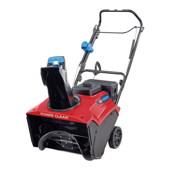
Toro POWER CLEAR 721 Service Manual
Hide thumbs
Also See for POWER CLEAR 721:
- Operator's manual (24 pages) ,
- Operator's manual (20 pages) ,
- Operator's manual (20 pages)
Chapters
Table of Contents

Related Manuals for Toro POWER CLEAR 721


Summary of Contents for Toro POWER CLEAR 721
- Page 1 Form No. 3438-776 Rev A POWER CLEAR® 721/821 Snowthrower Service Manual Published: July 2020 © 2020—The Toro® Company Original Instructions (EN) 8111 Lyndale Avenue South Contact us at www.Toro.com. Bloomington, MN 55420 All Rights Reserved...
- Page 2 Revision History Revision History Page 2 POWER CLEAR® 721/821 Snowthrower Service Manual 3438-776 Rev A...
- Page 3 The Toro Company RLC/SWS Customer Care Department 8111 Lyndale Avenue South Bloomington, MN 55420 The Toro Company reserves the right to change product specifications or make changes to this manual without notice. POWER CLEAR® 721/821 Snowthrower Page 3 Preface...
- Page 4 Service Procedure Icons The following icons appear throughout this Service Manual to bring attention to specific important details of a service procedure. Critical Process This icon is used to highlight: • Installing safety equipment (shields, guards, seat belts, brakes, and R.O.P.S. components) that may have been removed •...
- Page 5 Table of Contents Preface ........................ 3 Chapter 1: Safety .................... 1–1 Safety Instructions ..................1–2 Chapter 2: Specifications and Maintenance ............ 2–1 Specifications ....................2–2 Torque Specifications ................... 2–3 Chapter 3: Troubleshooting ................3–1 General Troubleshooting ................3–3 Chapter 4: Engine ................... 4–1 General Information ..................
- Page 6 Preface Page 6 POWER CLEAR® 721/821 Snowthrower Service Manual 3438-776 Rev A...
- Page 7 Chapter 1 Safety Table of Contents Safety Instructions ..........................1–2 Think Safety First ..........................1–2 POWER CLEAR® 721/821 Snowthrower Service Manual Page 1–1 Safety 3438-776 Rev A...
- Page 8 Safety Instructions DANGER This safety symbol means danger. When you see this symbol, carefully read the instructions that follow. Failure to obey the instructions could cause serious permanent injury, disability, or death. WARNING This safety symbol means warning. When you see this symbol, carefully read the instructions that follow.
- Page 9 Think Safety First (continued) Battery acid is poisonous and can cause burns. Avoid contact with skin, eyes and clothing. Battery gases can explode. Keep cigarettes, sparks and flames away from the battery. Avoid injury due to inferior parts… Use only original equipment parts to ensure that important safety criteria are met. Avoid injury to bystanders…...
- Page 10 Think Safety First (continued) The proper class of fire extinguisher should be used in case of fire. Class A extinguishers are for ordinary combustible materials such as paper, wood, cardboard, and most plastics. The numerical rating on these types of extinguishers indicates the amount of water it holds and the amount of fire it can extinguish.
- Page 11 Chapter 2 Specifications and Maintenance Table of Contents Specifications ............................2–2 Torque Specifications ........................... 2–3 Equivalents and Conversions......................2–8 U.S. to Metric Conversions ........................ 2–9 POWER CLEAR® 721/821 Snowthrower Service Manual Page 2–1 Specifications and Maintenance 3438-776 Rev A...
- Page 12 Specifications POWER CLEAR® 721/825 Model Name Power Clear Commercial Commercial Power Power Clear 721 Power Clear 721 R/E Power Clear 721 Clear 821 821 QZE Model 38752 / 38753 38754 38755 38756 38757 Clearing Width 8.27 cm (21 8.27 cm (21 inches) with Extended 8.27 cm (21 inches)
- Page 13 Torque Specifications The recommended fastener torque values are listed in the following tables. For critical applications, as determined by Toro, either the recommended torque or a torque that is unique to the application is clearly identified and specified in the service manual.
- Page 14 Metric Bolts and Screws g272209 Figure 2 Class 8.8 Class 10.9 Specifications and Maintenance: Torque Specifications Page 2–4 POWER CLEAR® 721/821 Snowthrower Service Manual 3438-776 Rev A...
- Page 15 Standard Torque for Dry, Zinc Plated, and Steel Fasteners (Inch Series) Thread Size Grade 1, SAE Grade 1 Bolts, Screws, SAE Grade 5 Bolts, Screws, SAE Grade 8 Bolts, Screws, 5, & 8 Studes & Sems with Studs & Sems with Regular Studs &...
- Page 16 Standard Torque for Dry, Zinc Plated, and Steel Fasteners (Metric Series) Thread Size Class 8.8 Bolts, Screws, Studs with Regular Class 10.9 Bolts, Screws, Studs with Regular Height Nuts (Class 8 or Stronger Nuts) Height Nuts (Class 10 or stronger Nuts) in-lb N •...
- Page 17 SAE Grade 8 Steel Set Screws Recommended Torque Thread Size Square Head Hex Socket 1/4 - 20 UNC 140 ± 20 in-lb 73 ± 12 in-lb 5/16 - 18 UNC 215 ± 35 in-lb 145 ± 20 in-lb 1/2 - 13 UNC 75 ±...
- Page 18 Equivalents and Conversions Decimal and Millimeter Equivalents Fractions Decimals Fractions Decimals 1/64 0.015625 0.397 33/64 0.515625 13.097 1/32 0.03125 0.794 16/32 0.53125 13.484 3/64 0.046875 1.191 35/64 0.546875 13.891 1/16 0.0625 1.588 9/16 0.5625 14.288 5/64 0.078125 1.984 37/64 0.578125 14.684 3/32 0.9375...
- Page 19 U.S. to Metric Conversions To Convert Into Multiply By Miles Kilometers 1.609 Yards Meters 0.9144 Feet Meters 0.3048 Linear Measurement Feet Centimeters 30.48 Inches Meters 0.0254 Inches Centimeters 2.54 Inches Millimeters 25.4 Square Miles Square Kilometers 2.59 Square Feet Square Meters 0.0929 Area Square Inches...
- Page 20 Specifications and Maintenance: Torque Specifications Page 2–10 POWER CLEAR® 721/821 Snowthrower Service Manual 3438-776 Rev A...
- Page 21 Chapter 3 Troubleshooting Table of Contents General Troubleshooting ........................3–3 POWER CLEAR® 721/821 Snowthrower Service Manual Page 3–1 Troubleshooting 3438-776 Rev A...
- Page 22 GEARS The Systematic approach to defining, diagnosing and solving problems. Gather Information • Information reported by the customer • Information observed by you • Establish the what, where and when of the issue Evaluate Potential Causes • Consider possible causes of the problem to develop a hypothesis •...
- Page 23 General Troubleshooting See Operator’s Manual for troubleshooting information. POWER CLEAR® 721/821 Snowthrower Service Manual Page 3–3 Troubleshooting: General Troubleshooting 3438-776 Rev A...
- Page 24 Troubleshooting: General Troubleshooting Page 3–4 POWER CLEAR® 721/821 Snowthrower Service Manual 3438-776 Rev A...
-
Page 25: Table Of Contents
Chapter 4 Engine Table of Contents General Information ..........................4–2 Service and Repairs ..........................4–3 Engine Replacement.......................... 4–4 Electric Starter Replacement ......................4–9 Muffler Guard Replacement ......................4–12 Muffler Replacement ........................4–15 Fuel Tank Replacement ........................4–17 POWER CLEAR® 721/821 Snowthrower Service Manual Page 4–1 Engine 3438-776 Rev A... -
Page 26: General Information
General Information The POWER CLEAR® 721 models utilize the Toro G210 engine, while the POWER CLEAR® 821 utilizes the Toro G250 engine. Engine: General Information Page 4–2 POWER CLEAR® 721/821 Snowthrower Service Manual 3438-776 Rev A... -
Page 27: Service And Repairs
Service and Repairs Engine Assembly g321046 Figure 3 Engine Engine Side Support Engine Plate Engine Support POWER CLEAR® 721/821 Snowthrower Service Manual Page 4–3 Engine: Service and Repairs 3438-776 Rev A... -
Page 28: Engine Replacement
Engine Replacement Engine Removal 1. Park the machine on a level surface. Stop the engine, wait for all moving parts to stop and remove the key. DANGER Fuel is very flammable and explosive under some conditions. Do not smoke or let flames or sparks in your work area. 2. - Page 29 Engine Removal (continued) g324731 Figure 5 8. Remove the rotor pulley assembly from the rotor shaft. 9. Remove the belt from the engine pulley and rotor pulley. 10. Remove the (5/16–24 x 1 1/4 inch) screw and Belleville washer securing the engine pulley to the engine shaft.
- Page 30 Engine Removal (continued) g323976 Figure 7 12. Remove the 2 (5/16-18 x 1 3/8 inch) screws and 2 nuts securing the engine support to the engine. Note: Do not flip the machine to replace the screws and nuts. g321401 Figure 8 13.
- Page 31 Engine Removal (continued) g323977 Figure 9 Engine Installation 1. Using an appropriate lifting device, install the engine onto the machine. 2. Install the 2 (5/16-18 x 1 3/8 inch) screws and 2 nuts securing the engine support to the engine. Note: Do not flip the machine to remove the screws and nuts.
- Page 32 Engine Installation (continued) 3. Install the 4 (M8 x 1.25 mm x 5/8 inch) bolts securing the engine to the engine plate. Torque the screws to 21.5–27 N • m (190–240 in-lb). g323976 Figure 11 4. Apply blue threadlocker to threads of the (5/16–24 x 1 1/4 inch) screw. Install the screw and Belleville washer securing the engine pulley to the engine shaft.
-
Page 33: Electric Starter Replacement
Engine Installation (continued) 6. Install the rotor pulley onto the rotor shaft. Apply blue threadlocker to threads of the new (1/4-20 x 7/8 inch) screw. Install the Belleville washer and screw securing the rotor pulley assembly to the rotor shaft. Torque the screw to 11.3 ±... - Page 34 Electric Starter Removal (continued) 2. Remove the 2 (#6 x 2.5 in) screws securing the electric starter switch box to the shroud. 3. Unwind the harness retainer clip and remove the electric starter wire from the harness retainer clip. g323979 Figure 15 4.
- Page 35 Electric Starter Installation (continued) 2. Install the electric starter by inserting the nose of the starter into the blower shroud and slide the mounting holes over the dowel pins. Install the 2 (M6 x 35) bolts securing the electric starter to the engine. Torque the bolts to 10 N •...
-
Page 36: Muffler Guard Replacement
Muffler Guard Replacement Muffler Guard Removal 1. Park the machine on a level surface. Stop the engine, wait for all moving parts to stop and remove the key. 2. Remove the 2 (1/4–10 x 13/16 inch) screws securing the LH shroud retainer to the LH shroud. - Page 37 Muffler Guard Removal (continued) g322776 Figure 21 4. Tip the muffler guard up towards the fuel tank to dislodge it from the fuel tank lip. 5. Remove the muffler guard from the engine. g323980 Figure 22 Muffler Guard Installation 1. Slide the lip of the muffler guard under the lip of the fuel tank. 2.
- Page 38 Muffler Guard Installation (continued) g323692 Figure 23 g322776 Figure 24 3. Install the 2 (1/4–10 x 13/16 inch) screws securing the LH shroud retainer to the LH shroud. Engine: Service and Repairs Page 4–14 POWER CLEAR® 721/821 Snowthrower Service Manual 3438-776 Rev A...
-
Page 39: Muffler Replacement
Muffler Guard Installation (continued) g320930 Figure 25 Muffler Replacement Muffler Removal 1. Remove the muffler guard from the engine. Muffler Guard Removal (page 4–12) 2. Remove the 2 nuts securing muffler assembly to cylinder head. g322787 Figure 26 3. Remove the muffler assembly and gasket from the engine. POWER CLEAR®... - Page 40 Muffler Removal (continued) g322788 Figure 27 Muffler Inspection 1. Inspect the muffler assembly for cracks, rust, or damage. Shake the muffler to check if the internal baffle is loose. Replace muffler if damaged. Muffler Installation 1. Install the new gasket onto the exhaust studs. Note: Refer to figure for correct gasket orientation.
-
Page 41: Fuel Tank Replacement
Muffler Installation (continued) 2. Install the muffler onto the exhaust studs. Install the 2 nuts securing the muffler to the exhaust studs. Torque the nuts to 29 N • m (21 ft-lb). g322787 Figure 29 Fuel Tank Replacement Fuel Tank Removal 1. - Page 42 Fuel Tank Removal (continued) g323979 Figure 30 5. Remove the (M6 x 20 mm) bolts securing the front of the fuel tank to the engine. The G210 engine has 3 (M6 x 20 mm) bolts and the G250 engine has 4 (M6 x 20 mm) bolts. Refer to the Specifications chapter to find the engine model.
- Page 43 Fuel Tank Removal (continued) g322779 Figure 32 7. Pivot the fuel tank to gain access to the fuel line. Slide the clamp away from the fuel filter and remove the fuel line from fuel filter fitting. g323984 Figure 33 Clamp 8.
- Page 44 Fuel Tank Installation (continued) g323984 Figure 34 Clamp 3. Install the fuel tank onto the engine. Apply blue threadlocker to the fuel tank bolt threads. Install the (M6 x 20 mm) fuel tank bolt securing the fuel tank to the engine. Torque the bolt to 8.47 N • m (75 in-lb). g322779 Figure 35 4.
- Page 45 Fuel Tank Installation (continued) g323982 Figure 36 5. Engines equipped with an electric starter only, wrap the harness retainer clip around the electric start wire. 6. Install the shroud onto the machine. Shroud Installation (page 5–10) DANGER Fuel is very flammable and explosive under some conditions. Do not smoke or let flames or sparks in your work area.
- Page 46 Engine: Service and Repairs Page 4–22 POWER CLEAR® 721/821 Snowthrower Service Manual 3438-776 Rev A...
- Page 47 Chapter 5 Chassis Table of Contents General Information ..........................5–2 Service and Repairs ..........................5–3 Shroud Replacement ......................... 5–8 Quick Shoot Controls Replacement ....................5–12 POWER CLEAR® 721/821 Snowthrower Service Manual Page 5–1 Chassis 3438-776 Rev A...
-
Page 48: General Information
General Information The chassis of both the 721 and 821 are the same size and use many of the same parts and fasteners. Chassis: General Information Page 5–2 POWER CLEAR® 721/821 Snowthrower Service Manual 3438-776 Rev A... -
Page 49: Service And Repairs
Service and Repairs Shroud and Quick Shoot Control Assemblies g321074 Figure 37 Deflector Trigger Chute Ring Seal Chute Deflector Chute Ring Retainer Chute Handle Pinion Sleeve Spacer Side Cover Gear Chute Ring Deflector Ratchet Hinge Pinion Bracket Deflector Hinge Pin Gear Pinion Deflector Seal Detent Pawl... - Page 50 Handle Assembly g324729 Figure 38 Spring Cover Rope Guide Control Bail Switch Box Support Clutch Extension Spring Box Support Upper Handle Support Cap Lower Handle Clutch Cable Adjuster Handle Lock Chassis: Service and Repairs Page 5–4 POWER CLEAR® 721/821 Snowthrower Service Manual 3438-776 Rev A...
- Page 51 Power Shoot Assembly g324730 Figure 39 Pulley Cover Trigger Spring Slider Pulley Plate Chute Lock Slider Handle RH Cable Clamp Short Chute Cable Trigger Handle Screw Slider Handle LH Long Chute Cable Cable Bracket Slider Track POWER CLEAR® 721/821 Snowthrower Service Manual Page 5–5 Chassis: Service and Repairs 3438-776 Rev A...
- Page 52 Quick Shoot Controls 1 g321048 Figure 40 Chassis: Service and Repairs Page 5–6 POWER CLEAR® 721/821 Snowthrower Service Manual 3438-776 Rev A...
- Page 53 Quick Shoot Controls 2 g321049 Figure 41 POWER CLEAR® 721/821 Snowthrower Service Manual Page 5–7 Chassis: Service and Repairs 3438-776 Rev A...
-
Page 54: Shroud Replacement
Shroud Replacement Shroud Removal 1. Park the machine on a level surface. Stop the engine, wait for all moving parts to stop and remove the key. 2. Remove the 3 (1/4-10 x 2 inch) plastite screws securing the chute to chute seal ring. - Page 55 Shroud Removal (continued) g320930 Figure 44 5. Remove the 2 (1/4-20 x 1 inch) screws securing the front of the shroud to the auger housing. 6. Remove the 3 (M4.2 x 2.25mm x 3/4 inch) screws securing the RH shroud to the side cover.
- Page 56 Shroud Removal (continued) g320932 Figure 46 Shroud Installation 1. Install the shroud onto the machine. Install the 2 (#6 x 2.5 inch) screws and 2 hex nuts securing the shroud to the switch box. Note: Install the starter plug to the shroud, if equipped with electric start. g320932 Figure 47 2.
- Page 57 Shroud Installation (continued) g320931 Figure 48 3. Install the 2 (1/4-20 x 1 inch) screws securing the front of the shroud to the auger housing. 4. Install the 2 (1/4-10 x 13/16 inch) screws securing the LH shroud retainer to the LH shroud.
-
Page 58: Quick Shoot Controls Replacement
Shroud Installation (continued) g320929 Figure 50 6. Install the chute and chute handle to the chute seal ring. Install the 3 (1/4-10 x 2 inch) plastite screws securing the chute handle and chute to chute seal ring. Torque the screws to 2.8–4 N • m (25–35 in-lb). Note: QZE models have a 1/4–10 x 1.5 inch plastite screw. - Page 59 Quick Shoot Controls Removal (continued) g320933 Figure 52 4. Remove the pinion spacer sleeve from the quick chute gear assembly. g320934 Figure 53 5. Using pliers, compress the cable locks and remove the black and gray cables from the pinion bracket. POWER CLEAR®...
- Page 60 Quick Shoot Controls Removal (continued) g320935 Figure 54 6. Turn the quick chute gear assembly over so that the cable retainer is facing upwards. Remove the cable retainer from the pinion gear. Note: With the cable retainer removed, note the orientation of the cable. g320936 Figure 55 Chassis: Service and Repairs...
- Page 61 Quick Shoot Controls Removal (continued) g320937 Figure 56 7. Unwrap and remove the cables from the pinion gear. Quick Shoot Controls Installation 1. With the pinion gear facing upwards, route the black cable into the bottommost gear slot. Insert the barrel end of the black cable into the slot and secure the cable under the gear tab.
- Page 62 Quick Shoot Controls Installation (continued) g320939 Figure 58 g320940 Figure 59 3. Insert the barrel end of the gray cable into the slot in the gear and secure the cable under the gear tab. Chassis: Service and Repairs Page 5–16 POWER CLEAR®...
- Page 63 Quick Shoot Controls Installation (continued) g320941 Figure 60 4. Wrap the gray cable around the top of the spool. g320942 Figure 61 POWER CLEAR® 721/821 Snowthrower Service Manual Page 5–17 Chassis: Service and Repairs 3438-776 Rev A...
- Page 64 Quick Shoot Controls Installation (continued) g320943 Figure 62 5. Slide the pinion gear into the pinion bracket and secure the cable locks. g320935 Figure 63 6. Insert the pinion spacer sleeve into the quick chute gear assembly. Chassis: Service and Repairs Page 5–18 POWER CLEAR®...
- Page 65 Quick Shoot Controls Installation (continued) g320934 Figure 64 7. Align the quick chute gear assembly between the chute gear retainer and chute support ring. Install the (1/4-20 x 2.25 inch) screw and lock nut securing the chute ring retainer and quick chute gear assembly to the chute support ring.
- Page 66 Quick Shoot Controls Installation (continued) g320933 Figure 66 8. Install the shroud onto the machine. Shroud Installation (page 5–10) Chassis: Service and Repairs Page 5–20 POWER CLEAR® 721/821 Snowthrower Service Manual 3438-776 Rev A...
- Page 67 Chapter 6 Drive System Table of Contents General Information ..........................6–2 Service and Repairs ..........................6–3 Belt Replacement..........................6–6 Rotor Replacement ..........................6–7 Paddle Replacement........................6–11 Scraper Replacement ........................6–13 POWER CLEAR® 721/821 Snowthrower Service Manual Page 6–1 Drive System 3438-776 Rev A...
-
Page 68: General Information
General Information All POWER CLEAR® 721 and 821 models utilize Toro's Power Propel self-propel system. Drive System: General Information Page 6–2 POWER CLEAR® 721/821 Snowthrower Service Manual 3438-776 Rev A... -
Page 69: Service And Repairs
Service and Repairs Auger Drive Assembly g324728 Figure 67 Cable Clutch Flat Idler Pulley Engine Pulley Spring Clip Belleville Washer Pivot Pushing Rotor Pulley Extension Spring Idler Arm Belt POWER CLEAR® 721/821 Snowthrower Service Manual Page 6–3 Drive System: Service and Repairs 3438-776 Rev A... - Page 70 Rotor Assembly g320854 Figure 68 Rotor Blade Rotor Blade Spacer Lock Nut Rotor Rotor Half Drive System: Service and Repairs Page 6–4 POWER CLEAR® 721/821 Snowthrower Service Manual 3438-776 Rev A...
- Page 71 Scraper Assembly g320957 Figure 69 Frame Brace Bearing Spacer Auger Housing Rubber Washer Belt Cover Shoulder Bolt Bearing Flange Lower Chute Thrust Washer Scraper Blade Ball Bearing POWER CLEAR® 721/821 Snowthrower Service Manual Page 6–5 Drive System: Service and Repairs 3438-776 Rev A...
-
Page 72: Belt Replacement
Belt Replacement Belt Removal 1. Remove the 3 (1/4-20 x 5/8 inch) screws securing the belt cover to the auger housing. Remove the belt cover from the auger housing. 2. Unhook the extension spring from the idler arm. g324732 Figure 70 3. -
Page 73: Rotor Replacement
Belt Installation (continued) g324731 Figure 72 3. Hook the extension spring to the idler arm. g324732 Figure 73 4. Install the belt cover to the auger housing. Install the 3 (1/4-20 x 5/8 inch) screws securing the belt cover to the auger housing. Torque the screws to 4.5–6.8 N •... - Page 74 Rotor Removal (continued) g320945 Figure 74 4. Remove the 3 (1/4-20 x 1 inch) rotor bearing screws securing the RH sideplate to the rotor assembly. g320946 Figure 75 5. Remove the rotor assembly from the auger housing. Drive System: Service and Repairs Page 6–8 POWER CLEAR®...
- Page 75 Rotor Removal (continued) g321390 Figure 76 6. Remove the (3/8-16 x 3/4 inch) screw securing the RH bearing spacer to the RH end cap. Remove the rubber washer, ball bearing, thrust washer, and bearing flange from the rotor assembly. Replace rotor parts as necessary. g321788 Figure 77 Screw...
- Page 76 Rotor Installation (continued) g321788 Figure 78 Ball Bearing Screw RH Bearing Spacer Thrust Washer Rubber Washer Bearing Flange 2. Install the rotor assembly into the auger housing. Install the 3 (1/4-20 x 1 inch) rotor bearing screws securing the RH sideplate to the rotor assembly. g320946 Figure 79 3.
-
Page 77: Paddle Replacement
Rotor Installation (continued) g320945 Figure 80 4. Install the belt. Belt Installation (page 6–6) Paddle Replacement Paddle Removal 1. Park the machine on a level surface. Stop the engine, wait for all moving parts to stop and remove the key. 2. - Page 78 Paddle Removal (continued) g321394 Figure 82 Paddle Installation 1. Install the paddles to the rotor assembly so that the thicker rubber layer is assembled to the forward facing side of the rotor assembly. Install the 4 (1/4-20 x 1 1/2 inch) screws, 4 spacers, and 4 washers securing the paddles to the 2 paddle spacers.
-
Page 79: Scraper Replacement
Paddle Installation (continued) g321394 Figure 84 2. Install the 4 (1/4-20 x 3/4 inch) Torx head screws securing the paddles together. g321393 Figure 85 Scraper Replacement Scraper Removal 1. Park the machine on a level surface. Stop the engine, wait for all moving parts to stop and remove the key. - Page 80 Scraper Removal (continued) g321395 Figure 86 3. Remove the 2 (3/8-16 x 2 1/2 inch) shoulder bolts securing the scraper to the auger housing. Remove the scraper from the auger housing. g321396 Figure 87 Scraper Installation 1. Flip the machine over so the auger housing is facing the floor. Install the scraper onto handle auger housing .
- Page 81 Scraper Installation (continued) g321396 Figure 88 2. Install the springs onto the LH and RH sides of the scraper. Install the lower hooks of the spring, so that the open end of the hooks are installed through the front holes of the scraper blade. g321395 Figure 89 POWER CLEAR®...