HP 9000 rp4440 Upgrade Manual
A7124a to ab383a configuration a7134a to ab383a configuration
Hide thumbs
Also See for 9000 rp4440:
- Maintenance manual (124 pages) ,
- User's & service manual (288 pages) ,
- Service manual (246 pages)
Table of Contents

Related Manuals for HP 9000 rp4440


Summary of Contents for HP 9000 rp4440
- Page 1 9000 rp4440 to hp Integrity rx4640 Upgrade Guide A7124A to AB383A Configuration A7134A to AB383A Configuration Manufacturing Part Number : upgr-rp4440-rx4640 November 2004 U.S.A. © Copyright 2004 Hewlett-Packard Development Company, L.P.
- Page 2 HP shall not be liable for technical or editorial errors or omissions contained herein. HP-UX Release 10.20 and later and HP-UX Release 11.00 and later (in both 32 and 64-bit configurations) on all HP 9000 computers are Open Group UNIX 95 branded products.
-
Page 3: Table Of Contents
Contents 1. Overview—Server Upgrade Overview ................7 Time Required. - Page 4 Contents Introduction ............... . 48 Required Tools.
- Page 5 Figure 1-3. Pedestal Mounted hp Server ........
- Page 6 Figures...
-
Page 7: Overview-Server Upgrade
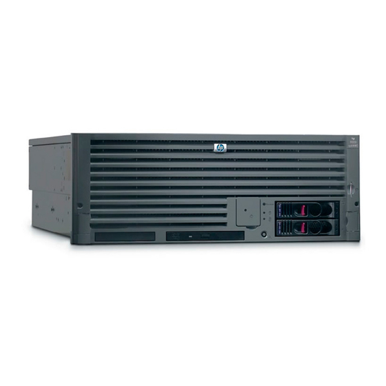
Overview—Server Upgrade Overview This guide presents instructions for upgrading the hp 9000 rp4440 to a hp Integrity rx4640 server. This change replaces the processor, updates server firmware, and enables the onboard VGA. Figure 1-1 hp 9000 rp4440 Server Time Required Upgrading the hp 9000 rp4440 Server may require several hours, depending on preparatory time, but you should plan for one hour of system downtime. - Page 8 Overview—Server Upgrade Overview Step 3. Shut down your server (disconnect AC power) and remove the processor extender board from the server chassis. Step 4. Remove old processors and install new processors on the processor extender board. Step 5. Set the IPF switch on the Processor Extender Board. Step 6.
-
Page 9: Common Procedures
Accessing a Rack Mounted Server The hp Server is designed to be rack mounted. The following procedure explains how to gain access to your hp Server that is mounted in an approved rack. For rack installation instructions, review the document titled Installation Guide, Mid-Weight Slide Kit, 5065-7291. -
Page 10: Insert The Server Into The Rack
Accessing a Pedestal Mounted Server The hp Server is also designed to be pedestal mounted. You do not need to remove the pedestal from the hp Server to gain access to internal components. The front bezel, front cover, and top cover may be removed with the pedestal attached to the hp Server. -
Page 11: Figure 1-3 Pedestal Mounted Hp Server
WARNING Ensure that the hp Server is properly grounded when performing remove-and-replace procedures. Use an antistatic wrist strap and grounding mat similar to those found in the hp Electrically Conductive Field Service Kit. Figure 1-3 Pedestal Mounted hp Server Chapter 1... -
Page 12: Front Bezel
Overview—Server Upgrade Front Bezel Front Bezel Figure 1-4 Removing and Installing the Front Bezel Chapter 1... -
Page 13: Removing The Front Bezel
Overview—Server Upgrade Front Bezel Removing the Front Bezel To remove the front bezel, perform the following step: Step 1. Grasp the front bezel at the outer edges and pull straight out. Installing the Front Bezel To install the front bezel, perform the following step: Step 1. -
Page 14: Front And Top Covers
Overview—Server Upgrade Front and Top Covers Front and Top Covers Figure 1-5 Removing and Installing the Front Cover Thumbscrews Chapter 1... -
Page 15: Removing The Front Cover
Removing the Front Cover To remove the front cover, perform the following steps: Step 1. If rack mounted, slide the hp Server out from the rack until it stops. See “Accessing a Rack Mounted Server” on page 9. Step 2. Remove the front bezel. See “Front Bezel” on page 12. -
Page 16: Figure 1-6 Removing And Installing The Top Cover
Overview—Server Upgrade Front and Top Covers Figure 1-6 Removing and Installing the Top Cover Thumbscrews Chapter 1... -
Page 17: Removing The Top Cover
Removing the Top Cover To remove the top cover, perform the following steps: Step 1. If rack mounted, slide the hp Server out from the rack until it stops. See “Accessing a Rack Mounted Server” on page 9. Step 2. Loosen the two captive thumbscrews that hold the top cover in place. -
Page 18: Processor Extender Board
Removing the Processor Extender Board To remove the processor extender board, perform the following steps: Step 1. If rack mounted, slide the hp Server out from the rack until it stops. See “Accessing a Rack Mounted Server” on page 9. -
Page 19: Figure 1-7 Processor Extender Board
Overview—Server Upgrade Processor Extender Board Step 5. Pull out on the extraction levers to unplug the processor extender board from the socket located on the midplane riser board. Figure 1-7 Processor Extender Board Chapter 1... -
Page 20: Installing The Processor Extender Board
Hot-Swap Chassis Fan Unit There are three hot-swap chassis fan units in the hp Server. Fan units 0, 1, and 2 are in the center of the chassis spanning the full chassis width. Fan units 0 and 1 are interchangeable and are in the left and center positions. -
Page 21: Figure 1-8 Hot-Swap I/O Chassis Fans Removal And Replacement
Hot-Swap I/O Chassis Fans Removal and Replacement To remove a hot-swap chassis fan unit, perform the following steps: Step 1. If rack mounted, slide the hp Server out from the rack until it stops. See “Accessing a Rack Mounted Server” on page 9. - Page 22 When the fan is functioning normally, the LED is off. • When the fan fails, the LED is lit. Step 4. Replace the top cover. Step 5. Replace the front bezel. Step 6. If rack mounted, slide the hp Server into the rack until it stops. Chapter 1...
-
Page 23: Upgrade Procedures For 1.3 Ghz (A7158A) Or 1.5 Ghz (A7159A) Processors
Upgrade Procedures for 1.3 GHz (A7158A) or 1.5 GHz (A7159A) Processors Chapter 2... -
Page 24: Introduction
This site provides patches to update rp4440 firmware and rp4440 to rx4640 firmware patches. Take care to down load and install the hp 9000 rp4440 Server to hp Integrity rx4640 Server firmware patch. Failure to do so will result in a non-bootable system. -
Page 25: Installing Processors
Upgrade Procedures for 1.3 GHz (A7158A) or 1.5 GHz (A7159A) Processors Introduction Removng Server Components To upgrade the server, remove the following components: Step 1. Extend the server from the rack.See “Extend the Server from the Rack” on page 9. Step 2. -
Page 26: Removing A Processor
Upgrade Procedures for 1.3 GHz (A7158A) or 1.5 GHz (A7159A) Processors Introduction Processor Load Order Processor modules are housed on the processor extender board located under the top cover in the top service bay. The processor extender board can hold between one and four processor modules. CPU 0 and CPU 1 are located on the top of the processor extender board, and CPU 2 and CPU 3 are located on the bottom. - Page 27 Upgrade Procedures for 1.3 GHz (A7158A) or 1.5 GHz (A7159A) Processors Introduction CAUTION Test the alignment of the assembly to the socket by gently moving the assembly back and forth with the palm of your hand—you should feel little or no sideplay. However, because the assembly is not yet tightened, it may tilt slightly towards the center of the extender board—this is acceptable.
-
Page 28: Figure 2-1 Processor Cable Placed Correctly
Upgrade Procedures for 1.3 GHz (A7158A) or 1.5 GHz (A7159A) Processors Introduction unplugged from their sockets when you move the cable into place under the heatsink. See Figure 2-1, “Processor Cable Placed Correctly,” and Figure 2-2, “Processor Cable Placed Incorrectly.” Figure 2-1 Processor Cable Placed Correctly Heatsink Cable is placed correctly and... - Page 29 Upgrade Procedures for 1.3 GHz (A7158A) or 1.5 GHz (A7159A) Processors Introduction Step 4. Plug in the processor cable to its socket on the extender board. Step 5. Place the sequencer frame over the processor. Chapter 2...
-
Page 30: Figure 2-3 Installing Processor On Extender Board
Upgrade Procedures for 1.3 GHz (A7158A) or 1.5 GHz (A7159A) Processors Introduction Step 6. Using the supplied Torx T15 driver, tighten the 6 T15 shoulder screws until they just bottom out. Follow the tightening sequence shown in Figure 2-3, “Installing Processor on Extender Board.” Figure 2-3 Installing Processor on Extender Board Tightening sequence for 6-shoulder screws is:... -
Page 31: Enabling The Onboard Vga
Upgrade Procedures for 1.3 GHz (A7158A) or 1.5 GHz (A7159A) Processors Introduction CAUTION Do not overtighten the 6 shoulder screws—they may shear off if overtightened. Stop tightening the shoulder screws when you feel them just bottom out. Step 7. On the Processor Extender Board, set the IPF/PA switch to the IPF position. Refer to Figure 2-4, “Processor Extender Board Switches.”... -
Page 32: Figure 2-5 Io Baseboard Select Switches
Upgrade Procedures for 1.3 GHz (A7158A) or 1.5 GHz (A7159A) Processors Introduction Step 1. On the IO baseboard, set the VGA Select Switch on as shown in Figure 2-5, “IO Baseboard Select Switches.” Figure 2-5 IO Baseboard Select Switches VGA Select Chapter 2... -
Page 33: Installing Server Components
Upgrade Procedures for 1.3 GHz (A7158A) or 1.5 GHz (A7159A) Processors Introduction Step 2. Remove the two screws securing the VGA port cover from the rear panel as shown in Figure 2-6, “VGA Port Cover Panel.” Figure 2-6 VGA Port Cover Panel VGA Port Cover Installing Server Components Install the following components in the server chassis:... - Page 34 Upgrade Procedures for 1.3 GHz (A7158A) or 1.5 GHz (A7159A) Processors Introduction # of Family/ Logical Cache Cache Model Processor Module CPUs Speed Size Size (hex.) State ------ ------- -------- ------ ------ ------- ------------ 1.3 GHz 3 MB None 1F/01 Active Note 1 CPU per CPU slot Step 7.
-
Page 35: Upgrade Procedures For 1.1 Ghz Mx2 Dual Processor Modules (A9730A)
Required Tools The hp 9000 rp4440 Server Upgrade Kit contains some of the tools needed to perform this procedure, including an ESD-safe workstation. Additionally, a long flat blade screwdriver is required. When performing this upgrade, you must use a static-dissipating work surface and a wrist strap. -
Page 36: Installing Processors
Upgrade Procedures for 1.1 GHz mx2 Dual Processor Modules (A9730A) Introduction Step 6. Disconnect the AC power cords from the server rear panel. Removng Server Components To upgrade the server, remove the following components: Step 1. Extend the server from the rack. See “Extend the Server from the Rack” on page 9. Step 2. -
Page 37: Removing A Processor
Upgrade Procedures for 1.1 GHz mx2 Dual Processor Modules (A9730A) Introduction Processor Load Order Processor moduless are housed on the processor extender board located under the top cover in the top service bay. The processor extender board can hold between one and four processor modules. CPU 0 and CPU 1 are located on the top of the processor extender board and, CPU 2 and CPU 3 are located on the bottom. - Page 38 Upgrade Procedures for 1.1 GHz mx2 Dual Processor Modules (A9730A) Introduction CAUTION Test the alignment of the assembly to the socket by gently moving the assembly back and forth with the palm of your hand—you should feel little or no sideplay. However, because the assembly is not yet tightened, it may tilt slightly towards the center of the extender board—this is acceptable.
-
Page 39: Figure 3-1 Processor Cable Placed Correctly
Upgrade Procedures for 1.1 GHz mx2 Dual Processor Modules (A9730A) Introduction unplugged from their sockets when you move the cable into place under the heatsink. See Figure 3-1, “Processor Cable Placed Correctly,” and Figure 3-2, “Processor Cable Placed Incorrectly.” Figure 3-1 Processor Cable Placed Correctly Heatsink Cable is placed correctly and is under the heatsink... - Page 40 Upgrade Procedures for 1.1 GHz mx2 Dual Processor Modules (A9730A) Introduction Step 4. Plug in the processor cable to its socket on the extender board. Step 5. Place the sequencer frame over the processor. Step 6. Using the CPU install tool, tighten the T15 shoulder screws 1, 2, 3, and 4 until they just bottom out. Follow the tightening sequence shown in Figure 3-3, “Installing Processor on Extender Board.”...
- Page 41 Upgrade Procedures for 1.1 GHz mx2 Dual Processor Modules (A9730A) Introduction CAUTION Do not overtighten the 6 shoulder screws—they may shear off if overtightened. Stop tightening the shoulder screws when you feel them just bottom out. Chapter 3...
-
Page 42: Figure 3-3 Installing Processor On Extender Board
Upgrade Procedures for 1.1 GHz mx2 Dual Processor Modules (A9730A) Introduction Figure 3-3 Installing Processor on Extender Board Tightening sequence for 4-shoulder screws is: 1,2,3,4,5,6 DO NOT OVERTIGHTEN! Torx-T15 Use supplied wrench for tightening shoulder screws and thumbscrews 2.5MM Allen Power cable protected by plastic sleeve... -
Page 43: Figure 3-4 Processor Extender Board Switches
Upgrade Procedures for 1.1 GHz mx2 Dual Processor Modules (A9730A) Introduction Step 8. On the Processor Extender Board, set the IPF/PA switch to the IPF position. Refer to Figure 3-4, “Processor Extender Board Switches.” Figure 3-4 Processor Extender Board Switches Set switch to IPF Step 9. -
Page 44: Enabling The Onboard Vga
Upgrade Procedures for 1.1 GHz mx2 Dual Processor Modules (A9730A) Introduction Enabling the Onboard VGA To enable the onboard VGA, perform the following steps: Step 1. On the IO baseboard, set the VGA Select Switch on as shown in Figure 3-5, “IO Baseboard Select Switches.”... -
Page 45: Installing Server Components
Upgrade Procedures for 1.1 GHz mx2 Dual Processor Modules (A9730A) Introduction Step 2. Remove the two T15 Torx screws securing the VGA port cover from the rear panel as shown in Figure 3-6, “VGA Port Cover Panel.”. Figure 3-6 VGA Port Cover Panel VGA Port Cover Installing Server Components Install the following components in the server chassis:... - Page 46 Upgrade Procedures for 1.1 GHz mx2 Dual Processor Modules (A9730A) Introduction Logical Cache Cache Model Processor Slot CPUs Speed Size Size (hex.) State ---- ------- -------- ------ ------ ------- ------------ 1.1 GHz 4 MB None 1F/01 Active Note 2 CPUs' per CPU slot Step 7.
-
Page 47: Upgrade Procedures For 1.5 Ghz (A9731Ax) Or 1.6 Ghz (A9732Ax Or A9733Ax) Dual Processors
Upgrade Procedures for 1.5 GHz (A9731AX) or 1.6 GHz (A9732AX or A9733AX) Dual Processors Chapter 4... -
Page 48: Introduction
This site provides patches to update rp4440 firmware and rp4440 to rx4640 firmware patches. Take care to down load and install the hp 9000 rp4440 Server to hp Integrity rx4640 Server firmware patch. Failure to do so will result in a non-bootable system. -
Page 49: Installing Processors
Upgrade Procedures for 1.5 GHz (A9731AX) or 1.6 GHz (A9732AX or A9733AX) Dual Processors Introduction Removng Server Components To upgrade the server, remove the following components: Step 1. Extend the server from the rack. See “Extend the Server from the Rack” on page 9. Step 2. -
Page 50: Removing A Processor
Upgrade Procedures for 1.5 GHz (A9731AX) or 1.6 GHz (A9732AX or A9733AX) Dual Processors Introduction Processor Load Order Processor modules are housed on the processor extender board located under the top cover in the top service bay. The processor extender board can hold between one and four processor modules. CPU 0 and CPU 1 are located on the top of the processor extender board and, CPU 2 and CPU 3 are located on the bottom. - Page 51 Upgrade Procedures for 1.5 GHz (A9731AX) or 1.6 GHz (A9732AX or A9733AX) Dual Processors Introduction CAUTION Test the alignment of the assembly to the socket by gently moving the assembly back and forth with the palm of your hand—you should feel little or no sideplay. However, because the assembly is not yet tightened, it may tilt slightly towards the center of the extender board—this is acceptable.
-
Page 52: Figure 4-1 Processor Cable Placed Correctly
Upgrade Procedures for 1.5 GHz (A9731AX) or 1.6 GHz (A9732AX or A9733AX) Dual Processors Introduction unplugged from their sockets when you move the cable into place under the heatsink. See Figure 4-1, “Processor Cable Placed Correctly,” and Figure 4-2, “Processor Cable Placed Incorrectly.”... - Page 53 Upgrade Procedures for 1.5 GHz (A9731AX) or 1.6 GHz (A9732AX or A9733AX) Dual Processors Introduction Step 4. Plug in the processor cable to its socket on the extender board. Step 5. Place the sequencer frame over the processor. Chapter 4...
-
Page 54: Figure 4-3 Installing Processor On Extender Board
Upgrade Procedures for 1.5 GHz (A9731AX) or 1.6 GHz (A9732AX or A9733AX) Dual Processors Introduction Step 6. Using the supplied Torx T15 driver, tighten the 6 T15 shoulder screws until they just bottom out. Follow the tightening sequence shown in Figure 4-3, “Installing Processor on Extender Board.” Figure 4-3 Installing Processor on Extender Board Tightening sequence for 6-shoulder screws is:... -
Page 55: Enabling The Onboard Vga
Upgrade Procedures for 1.5 GHz (A9731AX) or 1.6 GHz (A9732AX or A9733AX) Dual Processors Introduction CAUTION Do not overtighten the 6 shoulder screws—they may shear off if overtightened. Stop tightening the shoulder screws when you feel them just bottom out. Step 7. -
Page 56: Figure 4-5 Io Baseboard Select Switches
Upgrade Procedures for 1.5 GHz (A9731AX) or 1.6 GHz (A9732AX or A9733AX) Dual Processors Introduction Step 1. On the IO baseboard, set the VGA Select Switch on as shown in Figure 4-5, “IO Baseboard Select Switches.” Figure 4-5 IO Baseboard Select Switches VGA Select Chapter 4... -
Page 57: Installing Server Components
Upgrade Procedures for 1.5 GHz (A9731AX) or 1.6 GHz (A9732AX or A9733AX) Dual Processors Introduction Step 2. Remove the two screws securing the VGA port cover from the rear panel as shown in Figure 4-6, “VGA Port Cover Panel.”. Figure 4-6 VGA Port Cover Panel VGA Port Cover Installing Server Components Install the following components in the server chassis:... - Page 58 Upgrade Procedures for 1.5 GHz (A9731AX) or 1.6 GHz (A9732AX or A9733AX) Dual Processors Introduction # of Family/ Logical Cache Cache Model Processor Module CPUs Speed Size Size (hex.) State ------ ------- -------- ------ ------ ------- ------------ 1.5 GHz 4 MB None 1F/01 Active...
- Page 59 Chassis fan remove and replace Covers, front and top remove and replace Front Bezel remove and replace Processor extender board remove and replace Processors installing load order removing...