Table of Contents
Advertisement
Quick Links
NETWORK INTERFACE BOARD
HKSR-5804
• If this board is installed incorrectly, personal injury or damage to peripheral items may occur
due to fire, shock, or other accidental circumstances. To avoid such risks, installation should
be performed by trained service technicians.
• Refer to the SRW-5800's Operation Manual for instructions on how to operate the SRW-
5800 after installing this board.
To the technician installing the board
• Please refer to the Installation Manual supplied with this product for installation instructions.
• Before installing the board, be sure to turn off the SRW-5800 and wait until the internal
temperature drops.
OPERATION MANUAL
1st Edition (Revised 2)
[English]
Advertisement
Table of Contents

Related Manuals for Sony HKSR-5804


Summary of Contents for Sony HKSR-5804
- Page 1 NETWORK INTERFACE BOARD HKSR-5804 • If this board is installed incorrectly, personal injury or damage to peripheral items may occur due to fire, shock, or other accidental circumstances. To avoid such risks, installation should be performed by trained service technicians.
- Page 2 For the customers in Europe This equipment has been tested and found to comply with The manufacturer of this product is Sony Corporation, 1- the limits for a Class A digital device, pursuant to Part 15 7-1 Konan, Minato-ku, Tokyo, Japan.
-
Page 3: Table Of Contents
Maßnahmen durchzuführen und dafür aufzukommen. Setting Up the System .......7 Für Kunden in Europa Overview of the Setup Procedure....7 Der Hersteller dieses Produkts ist Sony Corporation, 1-7-1 Konan, Minato-ku, Tokyo, Japan. Preparations ..........7 Der autorisierte Repräsentant für EMV und Network Settings ..........8 Produktsicherheit ist Sony Deutschland GmbH, NFS Server Setup .........8... - Page 4 Outputting Tele-File Information....34 Other Functions ........36 Checking the Network Functions of This Board ............36 Displaying the IP Address of the Web Client ............36 Log File Management ........ 36 Using the Export Log Files ......36 Automatic Execution Using a Job File..38 Dubbing Uncompressed Data ....
-
Page 5: Overview
2K/4K material. Note The HKSR-5804 can transfer the material as the MXF files 1) A digital image file format that is generally used by image processing and only when the signal format is 4:2:2 YCbCr. -
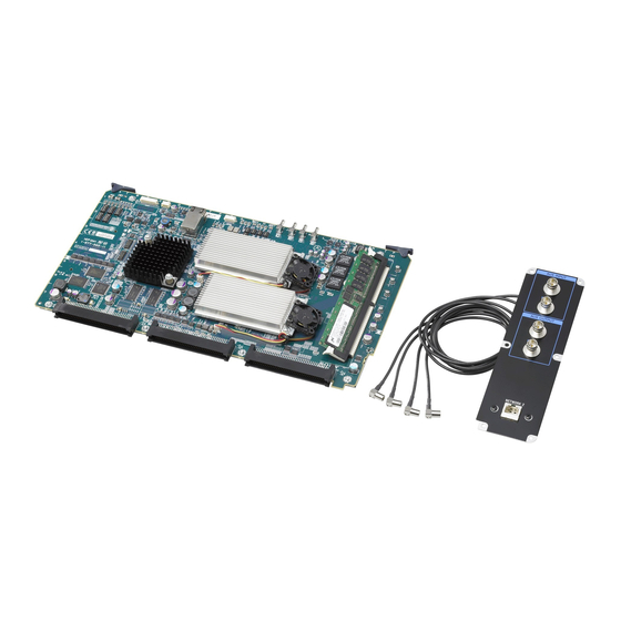
Page 6: System Configuration Example
This section explains the connectors that are added to the For details on how to specify the type of output signal, see connector panel of the SRW-5800 when the HKSR-5804 “To specify the type of signal output from the AUX is installed. -
Page 7: Setting Up The System
• Verwenden Sie beim Anschließen des NETWORK- Setting Up the System Kabels des Geräts an ein Peripheriegerät ein abgeschirmtes Kabel, um Fehlfunktionen aufgrund von Störungen zu vermeiden. Overview of the Setup Procedure The following diagram gives an overview of the procedure for setting up the system. -
Page 8: Network Settings
(NFS client/ web server) IP Address*: IP address of the VTR (example: 192.168.1.251) Subnet Mask*: subnet mask of the VTR (example: a) SRW-5800 installed with the HKSR-5804 255.255.255.0) Default Gateway: default gateway of the VTR Shared file server (example: 192.168.1.254) -
Page 9: Vtr Format Settings
For details on NFS server settings, consult your system Note administrator. The AUX output from the HKSR-5804 is not guaranteed when the SRW-5800 is set to a system format other than the ones described in the table above. VTR Format Settings... -
Page 10: Mounting The Nfs Server From The Web Application Through The Web Browser
When the server is mounted, the MOUNT button changes to the UMOUNT button. Set the LIST TYPE column to select how picture clips Enter the IP address of the VTR here. on the shared directory are displayed. Main Only: Only main picture clips are displayed. Main+Proxy: Both main picture clips and proxies are Notes displayed. -
Page 11: Proxy And Gui Settings
1) It is recommended that you leave the “input” specification as is during use Access the VTR from the web client to display the web of the networking function of the HKSR-5804. application, click the PROXY SETUP menu select About the VTR SETUP menu setting to prevent button, and then click the PROXY SETUP tab. - Page 12 Item Function/settings Item Function/settings GUI MODE Selects how the items in the WF ALPHA Specifies the waveform display are shown. transparency when the waveform(s) and the picture are : Items are divided into mixed. multiple tag displays. : Low transparency Flat: Items are shown in one display.
-
Page 13: Saving And Recalling The Gui Setup Data
Access the VTR from the web client to display the web Item Function/settings application, click the PROXY SETUP menu select PROXY DIR Determines the directory where button, and then click the COOKIE tab. the generated proxies are stored. Same as Main Files: Proxies are The COOKIE tag display opens. -
Page 14: Importing Files
Importing Files In this section, the settings required for importing compressed data (HDCAM-SR format) are described first. Next, the additional settings required for importing uncompressed data (DATA format) are explained, as well as settings that can only be made for uncompressed data. Overview of the Import Procedure The following diagram gives an overview of the import Set the following items. - Page 15 Item Function/settings Item Function/settings DEPTH Specifies the bit depth of the main COLOR Selects the information to be (for DPX, CIN, or picture files to be imported. (for DPX or CIN recorded to the COLORIMETRIC TIFF files) 8: 8 bits files) field of the header of imported DPX files or the Channel 1...
- Page 16 Notes files) the header of imported DPX files or the Input Device field of the • In order to use the MXF files with the HKSR-5804, the header of imported CIN files. VTR must be SRW-5800/2 or later. Auto : The cassette ID in the •...
-
Page 17: File Name And Directory Setup
For uncompressed data, the following three items must be specified. In the table below, the default setting is indicated by an asterisk (*). Item Function/settings FILE TYPE Selects the file type of main picture files to be imported from the VTR to the NFS server. - Page 18 To delete a directory Item Function/settings Click the Select Directory box and select the directory TC check box When checked, the value of the IN that you want to delete. Then click the RMDIR button. point timecode converted into frame count is set as the starting Set the following items.
-
Page 19: Setting In/Out Points On A Tape
clip_###_@@@@@@.dpx target directory (step 2 in “File Name and Directory Setup” on page 17). In the table below, the default setting is indicated by an Serial number that is added to each DPX file in asterisk (*). the clip. The default starting number is “000000.” The starting number can be changed. - Page 20 Loading a clip sequence from the export log display For details, see “To load a clip sequence from the export log display” on page 28. Loading a clip sequence from Tele-File By selecting the clip from the clip list stored in the Tele- File label on the cassette tape, the clip sequence can be loaded directly to the clip list.
-
Page 21: Importing The Clips
/XXXX/XXX/:##:## Picture ID of the OUT point Picture ID of the IN point Path to the directory to be imported Checking the clip list and transposing clips The procedure is the same as “Checking the clip list and transposing clips” on page 20 in “Setting IN/OUT Points on a Tape.”... - Page 22 When one of these messages appears with ERR ABORT set to “enable,” importing is aborted. Note When ERR ABORT is set to “disable,” importing continues as long as possible even after an error message appears. Note, however, that normal operational results may not be guaranteed.
-
Page 23: Exporting Files
Item Function/settings Exporting Files RANGE Specifies how the signal level is converted for the main picture files to be exported. In this section, the settings required for exporting Full t Head: During export, full-range video (0-1023) is compressed to compressed data (HDCAM-SR format) are described first. the effective video signal range (64- Next, the additional settings required for exporting 940) of video signals with... -
Page 24: Selecting The Clip To Be Exported
Item Function/settings IN TC(insert) Specifies how the recording start position (IN point) on the tape is determined. Preset : In the VTR CONTROL tag display in the EXPORT menu, use the MarkIn button For uncompressed data, DPX/CIN files in the NFS server or enter the timecode to are recorded basically as is from the file name to the specify the IN point. - Page 25 Number.” Then, the serial number of the file name To specify the clips to be exported by loading an export list determines the export IN point to allow the file to be recorded back to its original position on the tape . You can specify the clip files to be exported by loading an export list created using an external editor.
- Page 26 Normally, when no files are in the selected directory, the export of clip files cannot be started. Note, however, that in this case, exporting can be done through automatic execution using a job file (see page 38). Set the following items in the DISK CONTROL tag display.
-
Page 27: Specifying The Recording Start Position (In Point) On The Tape
Be Exported.” Exporting the Clips For uncompressed data, the DURATION box in the CLIP LIST area shows the timecode of the HDCAM-SR format The export procedure is the same for both compressed data compressed data, so that the amount of tape used can be and uncompressed data. - Page 28 recorded to the tape. Clicking the button twice terminates cassette ID (Tele-File ID) and information is added each exporting instantly. time the clips are exported to the same cassette tape. When “Insert” is set for EDIT MODE, clicking the CANCEL button once terminates exporting instantly. Error messages The table below lists the error messages that are displayed on the VTR during exporting and their meanings.
-
Page 29: Controlling The Vtr
Controlling the VTR VTR CONTROL Window You can control playback with the tape operation buttons in the VTR CONTROL window in the HOME, IMPORT, and EXPORT menus, and monitor the picture on the HD monitor. When rotating the mouse wheel on the proxy, the VTR can be played in jog mode. -
Page 30: Viewer Window
Category Function Menu/tab Ctrl+Shift+H Opens the HOME menu. control Ctrl+Shift+I Opens the IMPORT menu. operations Ctrl+Shift+E Opens the EXPORT menu. Ctrl+Shift+V Opens the VTR SETUP menu. Ctrl+Shift+P Opens the PROXY SETUP menu. Ctrl+Shift+D Opens the DISK SETUP menu. Ctrl+T Moves to the next tag Ctrl+Shift+T display. -
Page 31: Controlling The On-Board Functions
Item Function/settings Controlling the On-board PRESET Up to eight downconverter Functions settings can be stored as presets (Preset1 to Preset 8). Note Unlike the lookup table banks, Downconverter Settings downconverter settings are stored on cookies. You can use the The downconverter settings can be made through the web COOKIE tag display in the application. -
Page 32: Lookup Table (Lut) Settings
Item Function/settings Item Function/settings MODE Specifies whether to allow a MON DC Selects the downconverter setting change in the aspect ratio of the that is applied to the monitor output. cropped picture. Auto : Settings that match the size Keep Aspect : The aspect ratio of of the source picture are the cropped picture is... -
Page 33: Color Control Function For The Monitor Output
Set the following items. Set the following items. In the table below, the default setting is indicated by an Item Function/settings asterisk (*). BANK Selects one of the eight banks (BANK 1 to BANK 8). Item Function/settings WP check box Check this box when you do not COLOR SPACE Specifies the monitor output... -
Page 34: Outputting Tele-File Information
Access the VTR from the web client to display the web application, click the VTR SETUP menu select button, and then click the CASSETTE tab. The CASSETTE tag display appears. Set the following items. In the table below, the default setting is indicated by an asterisk (*). - Page 35 To select all the clips with the same VTR Item Explanation format at one time TAKE Enter the take name (number). Double-click a clip with a VTR format that you want to select while holding down the Shift key and the Ctrl CIRCLE Enter the okay mark.
-
Page 36: Other Functions
Note Other Functions The thumbnail directory is created only when the LOG PROXY box in the DISK CONTROL tag display of the EXPORT menu is set to “Copy to Log Directory.” Checking the Network Functions of For details, see “About the “Copy to Log Directory” This Board setting in LOG PROXY”... - Page 37 Export log files for each cassette ID Export log file for the cassette A DPX files NFS server Cassette ID: A Web client VTR installed with the HKSR-5804 E-mail or removable media Cassette ID: A Facility 2 Web client Export log file for the cassette A...
-
Page 38: Automatic Execution Using A Job File
The contents of the selected job file are displayed. Dubbing Uncompressed Data By connecting two SRW-5800 units installed with the HKSR-5804, you can carry out tape dubbing through their AUX connectors. For details on connectors not described in this manual or the VTR SETUP menu, refer to the Operation Manual supplied with the SRW-5800. - Page 39 “B01: NW I/O mode” in the VTR SETUP menu is set to “DUB”. Be sure to set this item to “MON” after dubbing SRW-5800 finishes. (player) • In the case of the 3G-SDI format, this board does not support dubbing through the AUX connectors. BNC cable SRW-5800 (recorder)
-
Page 40: Specifications
• Always make a test recording, and verify that it was Interface 1000Base-T (conforming to IEEE802- recorded successfully. 3ab) SONY WILL NOT BE LIABLE FOR DAMAGES OF Jumbo frame (up to 9000 bytes) ANY KIND INCLUDING, BUT NOT LIMITED TO, Protocol TCP/IP, UDP/IP... -
Page 41: Appendix
# Comment Appendix LUT: 3 1024 # (Line No,) Output value LUT File Formats Applicable to This Board Examples of the five lookup table (LUT) file formats • applicable to this board are shown below. • Note • Line numbers (“Lx” in the tables below) do not appear in L1023 1023 the actual LUT files. -
Page 42: Job File Samples
# Comment # Comment LUT10 # (Line No,) Input Output R Output G Output B value # (Line No,) Input Output R Output G Output B value • • • • • • L1023 1022 1023 1023 1023 L1023 1022 1023 1023 1023... - Page 43 Sample 1 Importing compressed data <?xml version="1.0" encoding="UTF-8"?> <jobinfo> <general> <mode>1</mode> <!-- 1:Codec Import/2:Codec Export/3:UC Import/4:UC Export --> <log> <control></control> <!-- 0:disable/*1:enable(Log Dir)/2:enable(Selected Dir) --> <text></text> <!-- 30 characters --> </log> <proxy> <!-- Proxy Setting for GUI/AutoGen --> <type></type> <!-- 0:BMP/*1:JPG --> <size></size>...
- Page 44 <!-- 0/2/4/6/8/10/12/*255(auto) (for MXF only) --> </audio> <header> <transfer></transfer> <!-- 0:User Defined/1:Printing Density/*2:Linear/3:Logarithmic/4:Unspecified Video/5:SMPTE 274M/6:ITU-R 709-4 --> <color></color> <!--(DPX) 0:User Defined/1:Printing Density/4:Unspecified Video/*5:SMPTE 274M/6:ITU-R 709-4 --> <!--(CIN) 1:Printing Density/*4:CCIR-XA/11(Rec.709) --> <meta></meta> <!-- *0:Off/1:All Data/2:Keykode Only --> <reel> <mode></mode> <!-- *0:Auto/1:Manual/2:Cassette ID --> <name></name>...
- Page 45 Sample 2 Exporting compressed data <?xml version="1.0" encoding="UTF-8"?> <jobinfo> <general> <mode>2</mode> <!-- 1:Codec Import/2:Codec Export/3:UC Import/4:UC Export --> <log> <control></control> <!-- 0:disable/*1:enable(Log Dir)/2:enable(Selected Dir) --> <proxy></proxy> <!-- 0:Link to Original File/*2:Copy to Log Directory --> <text></text> <!-- 30 characters --> </log>...
- Page 46 <dir></dir> <!-- 128 characters(depends on full pathname) --> <!--e.g.) /export_clip/--> <base></base> <!-- 32 characters --> <start></start> <!-- Start ID --> <end></end> <!-- End ID --> <digit></digit> <!-- 1-10 --> <ext></ext> <!-- 8 characters(case sensitive) with ’.’ --> <!--e.g.) .dpx--> </name> <tc>...
- Page 47 Sample 3 Importing uncompressed data <?xml version="1.0" encoding="UTF-8"?> <jobinfo> <general> <mode>3</mode> <!-- 1:Codec Import/2:Codec Export/3:UC Import/4:UC Export --> <log> <control></control> <!-- 0:disable/*1:enable(Log Dir)/2:enable(Selected Dir) --> <text></text> <!-- 30 characters --> </log> <proxy> <!-- Proxy Setting for GUI/AutoGen --> <type></type> <!-- 0:BMP/*1:JPG --> <size></size>...
- Page 48 Sample 4 Exporting uncompressed data <?xml version="1.0" encoding="UTF-8"?> <jobinfo> <general> <mode>4</mode> <!-- 1:Codec Import/2:Codec Export/3:UC Import/4:UC Export --> <log> <control></control> <!-- 0:disable/*1:enable(Log Dir)/2:enable(Selected Dir) --> <proxy></proxy> <!-- 0:Link to Original File/*2:Copy to Log Directory --> <text></text> <!-- 30 characters --> </log>...
- Page 49 <!-- *0:RGB/2:CBYCRY/5:Data(non-Image) --> <proxy> <!-- Existing proxy informatins for this sequence --> <type></type> <!-- 0:BMP/1:JPG/2:NONE --> <size></size> <!-- 0:160/2:320/3:640 --> <dirmode></dirmode> <!-- 0:Same as Main Files/1:Proxy Directory/2:Resolution Directory --> </proxy> </file> </sequence> </jobinfo>...
- Page 50 The material contained in this manual consists of information Trademarks that is the property of Sony Corporation and is intended solely • Windows and Internet Explorer are registered trademarks of for use by the purchasers of the equipment described in this Microsoft Corporation in the United States and/or other manual.
- Page 51 Sony Corporation HKSR-5804 (SY) 4-115-947-03 (1) © 2008...