Sony STR-DE435 Service Manual
Hide thumbs
Also See for STR-DE435:
- Operating instructions manual (157 pages) ,
- Service manual (46 pages) ,
- Limited warranty (1 page)
Table of Contents
Advertisement
Quick Links
All manuals and user guides at all-guides.com
STR-DE435/DE535/SE491/V424/V525
SERVICE MANUAL
Ver 1.1 2003. 05
Dolby Laboratories Licensing Corporation.
"DOLBY" the double-D symbol a "AC-3" and "PRO LOGIC"
are trademarks of Dolby Laboratories Licensing Corporation.
POWER OUTPUT AND TOTAL HARMONIC
DISTORTION
With 8-ohm load, both channels driven, from 20
20,000 Hz rated 100 watts per channel minimum
RMS power, with no more than 0.09%
harmonic distortion from 250 milliwatts to rated
output.
STR-SE491:
a) 40Hz
b) 0.5%
Amplifier section
Stereo mode
STR-DE535/DE435:
(8Ω at 20Hz – 20kH
less than 0.09% total
harmonic distortion)
100W + 100W
STR-SE491:
(8Ω at 40Hz – 20kHz less
than 0.5% total harmonic
distortion)
100W + 100W
Surround mode and
STR-DE535/435:
5.1CH/DVD mode
(8Ω at 1kHz, THD 0.8%)
Front: 100W/ch
Center*: (Pro Logic Mode)
100W
Rear*: 100W/ch
STR-SE491:
(8Ω at 1kHz, THD 0.5%)
Front: 100W/ch
Center*: 100W
Rear*: 100W/ch
Sony Corporation
9-928-848-12
2003E16-1
Home Audio Company
© 2003.05
Published by Sony Engineering Corporation
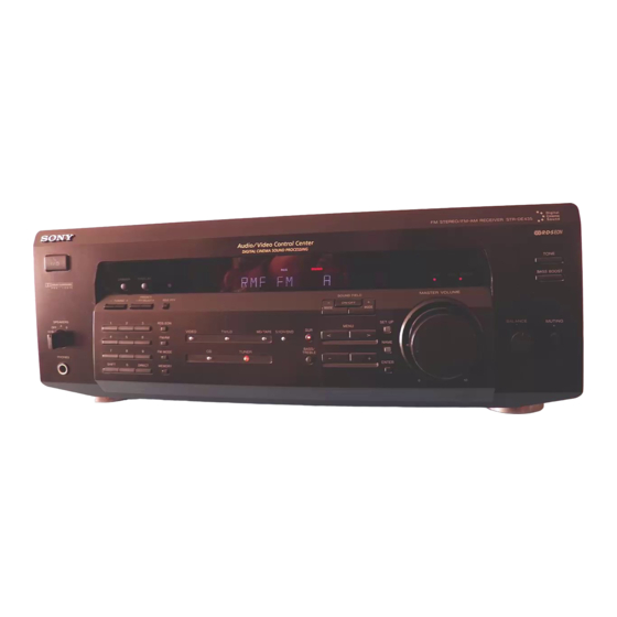
Photo: STR-DE535
SPECIFICATIONS
Frequency response
a)
–
b)
total
Inputs
Sensitivity
PHONO
(except STR-
4mV
DE435)
CD,
5.1CH/
DVD,
MD/TAPE,
250mV
TV/SAT,
VIDEO
Outputs
Australian Model
PHONO: RIAA
Muting
equalization curve
BASS BOOST
±0.5dB
TONE
(except STR-DE435)
TV/SAT, CD, MD/
Tuner section
TAPE, VIDEO, 5.1CH/
FM Stereo, FM/AM superheterodyne tuner
DVD
10Hz – 50kHz ± 1dB
FM tuner section
Tuning range
Impedance
S/N
Antenna terminals
Intermediate frequency
50
Sensitivity
86dB
kilohms
Usable sensitivity
S/N
50
96dB
kilohms
Harmonic
distortion at 1kHz
Separation
MD/TAPE REC OUT:
Frequency response
Voltage: 250mV,
Selectivity
Impedance: 10kilohms
VIDEO AUDIO OUT:
Voltage: 250mV,
Impedance: 10kilohms
WOOFER:
Voltage: 2V
Impedance: 1kilohms
PHONES: Accepts low
and high impedance
headphones
FM STEREO FM-AM RECEIVER
US Model
STR-DE435/DE535/SE491
Canadian Model
STR-DE435/DE535
AEP Model
STR-DE435
E Model
STR-DE435/DE535
STR-DE435/DE535
Chinese Model
STR-V424/V525
Full mute
+8dB at 70Hz
±8dB at 100Hz and
10kHz
87.5 – 108.0MHz
75Ω, unbalanced
10.7MHz
Mono: 18.3dBf,
4.5µV
Stereo: 38.3dBf,
45µV
11.2dBf, 2µV (IHF)
Mono: 76dB
Stereo: 70dB
Mono: 0.3%
Stereo: 0.5%
45dB at 1kHz
+0.5
30Hz –15kHz
dB
–2
60dB at 400kHz
— Continued on next page —
Advertisement
Table of Contents

Related Manuals for Sony STR-DE435


Summary of Contents for Sony STR-DE435
- Page 1 PHONES: Accepts low (8Ω at 1kHz, THD 0.5%) and high impedance Front: 100W/ch headphones — Continued on next page — Center*: 100W Rear*: 100W/ch FM STEREO FM-AM RECEIVER Sony Corporation 9-928-848-12 2003E16-1 Home Audio Company © 2003.05 Published by Sony Engineering Corporation...
- Page 2 Dimensions (17 × 6 × 14 inches) Mass (Aporox.) STR-DE535: 11.1kg (24 lb 6 oz) STR-DE435: 11.0kg (24 lb 3 oz) STR-DE491: 11.2kg (24 lb 9 oz) Supplid accessories FM wire antenna (1) AM loop antenna (1) Remote commander (remote) (1)
-
Page 3: Table Of Contents
CRITIQUES POUR LA SÉCURITÉ DE FONCTIONNEMENT. NE COMPONENTS WITH SONY PARTS WHOSE PART NUMBERS REMPLACER CES COMPOSANTS QUE PAR DES PIÈSES SONY APPEAR AS SHOWN IN THIS MANUAL OR IN SUPPLEMENTS DONT LES NUMÉROS SONT DONNÉS DANS CE MANUEL OU PUBLISHED BY SONY. -
Page 4: Genetal
All manuals and user guides at all-guides.com SECTION 1 GENETAL Front Panel 2 3 4 56 7 8 9 !º !¡ !™ !£ !¢ !∞ #¢ #£ #™ #¡ #º @ª @¶ @∞ @¢ @£ @™ @¡ @º !ª !• !¶... - Page 5 All manuals and user guides at all-guides.com Rear Panel !¶ !£ !™ !¡ !º !§ !∞ !¢ ANTENNA (FM/AM) 5.1CH/DVD MONITOR WOOFER SPEAKER (REAR) SPEAKER (CENTER) AC power cord AC OUTLET SPEAKER (FRONT) !º IMPEDANCE SELECTOR (DE535 only) !¡ S-LINK (DE535 only) !™...
-
Page 6: Test Mode
All manuals and user guides at all-guides.com SECTION 2 TEST MODE SOFTWARE VERSION DISPLAY MODE ALL CLEAR MODE * The software version is displayed. * All preset contents are cleared when this mode is activated. Use * Procedure: this mode before returning the product to clients upon completion While depressing the MD/TAPE and the DIRECT buttons of repair. -
Page 7: Diagrams
All manuals and user guides at all-guides.com STR-DE435/DE535/SE491/V424/V5 SECTIION 3 DIAGRAMS 3-1. CIRCUIT BOARDS LOCATION THIS NOTE IS COMMON FOR PRINTED WIRING BOARDS AND SCHEMATIC DIAGRAMS. (In addition to this necessary note is printed in each block.) VOLTAGE SELECTOR board For schematic diagrams. -
Page 8: Block Diagrams
All manuals and user guides at all-guides.com STR-DE435/DE535/SE491/V424/V525 3-2. BLOCK DIAGRAMS — MAIN SECTION — DOLBY PROLOGIC SURROUND AUDIO SELECT MATRIX DECODER PROCESSOR IC204 IC301 IC302 L.P.F LINE AMP TUNER UNIT IC202 L OUT L OUT IC400 L OUT TUNER RY401 75Ω... -
Page 9: Power Section
All manuals and user guides at all-guides.com STR-DE435/DE535/SE491/V424/V5 — POWER SECTION — POWER AMP(L) IC501 J501 R CH 13 VCC PHONES RY503 BOOSTER RELAY Q506 DRIVE LIMITER Q513 Q504 S101 • RCH is omitted LIMITER Q511 SPEAKERS • Signal Path... -
Page 10: Printed Wiring Board - Input Section
All manuals and user guides at all-guides.com STR-DE435/DE535/SE491/V424/V525 • Refer to page 7 for Circuit Boards Location. 3-3. PRINTED WIRING BOARD — INPUT SECTION — • Semiconductor Location Ref. No. Location IC201 C-12 IC202 IC203 IC204 E-11 IC230 B-12 IC501... -
Page 11: Schematic Diagram - Input Section
All manuals and user guides at all-guides.com STR-DE435/DE535/SE491/V424/V5 3-4. SCHEMATIC DIAGRAM — INPUT SECTION — • Refer to page 39 for IC Block Diagrams. • Refer to page 8 for Waveforms. 4.332 AEP,EE,CIS MODEL — 15 — — 16 —... -
Page 12: Printed Wiring Board - Surround Section
All manuals and user guides at all-guides.com STR-DE435/DE535/SE491/V424/V525 3-5. PRINTED WIRING BOARD — SURROUND SECTION — • Refer to page 7 for Circuit Boards Location. EXCEPT SE491 MODEL • Semiconductor Location Ref. No. Location Ref. No. Location Ref. No. Location Ref. -
Page 13: Schematic Diagram - Surround Section
All manuals and user guides at all-guides.com STR-DE435/DE535/SE491/V424/V5 3-6. SCHEMATIC DIAGRAM — SURROUND SECTION — • Refer to page 39 for IC Block Diagrams. C419 -5V REG Q422 DTC124ES F.MUTE DE435 : US,CND DE535/V525 MODEL — 19 — — 20 —... -
Page 14: Printed Wiring Board - Display Section
All manuals and user guides at all-guides.com STR-DE435/DE535/SE491/V424/V525 3-7. PRINTED WIRING BOARD — DISPLAY SECTION — • Refer to page 7 for Circuit Boards Location. • Semiconductor Location Ref. No. Location D107 C-10 D108 C-10 D110 C-14 D111 B-13 D112... -
Page 15: Schematic Diagram - Display Section
All manuals and user guides at all-guides.com STR-DE435/DE535/SE491/V424/V5 3-8. SCHEMATIC DIAGRAM — DISPLAY SECTION — • Refer to page 37 for IC Pin Functions. • Refer to page 8 for Waveforms. The components identified by Les composants identifiés par mark ! or dotted line with mark une marque ! sont critiques ! are critical for safety. -
Page 16: Printed Wiring Board - Key Section
All manuals and user guides at all-guides.com STR-DE435/DE535/SE491/V424/V525 3-9. PRINTED WIRING BOARD — KEY SECTION — • Refer to page 7 for Circuit Boards Location. • Semiconductor Location Ref. No. Location D119 D120 D122 A-10 D123 D124 D125 D126 D127... -
Page 17: Schematic Diagram - Key Section
All manuals and user guides at all-guides.com STR-DE435/DE535/SE491/V424/V5 3-10. SCHEMATIC DIAGRAM — KEY SECTION — — 27 — — 28 —... -
Page 18: Printed Wiring Board - Rear Amp Section
All manuals and user guides at all-guides.com STR-DE435/DE535/SE491/V424/V525 3-11. PRINTED WIRING BOARD — REAR AMP SECTION — • Refer to page 7 for Circuit Boards Location. ,V525 AEP,EE,CIS MODEL T901 POWER TRANS FORMER VOLTAGE SELECTOR CNV903 • Semiconductor Location Ref. No. Location... -
Page 19: Schematic Diagram - Rear Amp Section
All manuals and user guides at all-guides.com STR-DE435/DE535/SE491/V424/V5 3-12. SCHEMATIC DIAGRAM — REAR AMP SECTION — CNV712 P.AMP BOARD P.AMP BOARD CNP801 CNP802 T4AL 250V: E, MY, SP, AUS, CH TL6.3A 250V: AEP, EE, CIS 6.3A 125V: US, CND 250V... -
Page 20: Printed Wiring Board - Power Amp Section
All manuals and user guides at all-guides.com STR-DE435/DE535/SE491/V424/V525 3-13. PRINTED WIRING BOARD — POWER AMP SECTION — • Refer to page 7 for Circuit Boards Location. US,CND,E • Semiconductor Location Ref. No. Location Ref. No. Location Ref. No. Location Ref. No. Location Ref. -
Page 21: Schematic Diagram -Power Amp Section
All manuals and user guides at all-guides.com STR-DE435/DE535/SE491/V424/V5 3-14. SCHEMATIC DIAGRAM —POWER AMP SECTION — C803,C804 F801,F802 EXCEPT CND,AEP,EE,E,CIS/SE491 MY,SP,AUS,E,CH:8.0A 125V ;10000/71V AEP,EE,CIS:TL6.3A 250V CND,SE491/DE535:E;8200/71V AEP,EE,CIS;10000/63V US,CND TO TRANS CNS801 US,CND TO TRANS CNS802 CNP711 The components identified by Les composants identifiés par... -
Page 22: Ic Pin Function Description
All manuals and user guides at all-guides.com STR-DE435/DE535/SE491/V424/V525 3-15. IC PIN FUNCTION DESCRIPTION • IC100 uPD780208GF-032-3BA/M62438FP-600D SYSTEM CONTROL (DISPLAY BOARD) Pin No. Pin Name Description Pin No. Pin Name Description VDD.+5V — Power Supply (+5 V). VOL – Volume –. - Page 23 All manuals and user guides at all-guides.com IC301 (SURR BOARD) CXA8079S 47 46 45 44 43 42 41 30 29 28 26 25 34 33 C-TRIM R-B.P.F. L+R-RECT VCS-LOG N-GEN N-BPF BAL-DET L-R-RECT DUAL-TIME BALCONT CMODE SMUTE N-OH R-RECT COMB-NET VCRX8 VLR-LOG L-B.P.F.
-
Page 24: Explodeo Views
All manuals and user guides at all-guides.com SECTION 4 EXPLODED VIEWS NOTE: • -XX, -X mean standardized parts, so they may • The mechanical parts with no reference number The components identified by mark ! or have some differences from the original one. in the exploded views are not supplied. - Page 25 1-672-997-11 SPK SELECT BOARD * 30 4-982-682-01 CASE (414532) 4-216-924-01 INDICATION PLATE (DE435:US,CND,AUS/DE535:US,CND,E,AUS/SE491/V424) 4-996-698-01 EMBLEM, SONY (EXCEPT V525) X-4947-722-1 CASE ASSY (BLACK) (AEP,MY,SP,EE,CIS) 4-996-698-11 EMBLEM, SONY (V525) X-4947-723-1 CASE ASSY (V525) 4-957-383-01 KNOB (F14) (BLACK) X-4951-513-1 CASE ASSY (SILVER) (AEP)
-
Page 26: Chassis Section
All manuals and user guides at all-guides.com Ver 1.1 2003.05 4-2. CHASSIS SECTION AEP, E,EE US, CND CIS, MY, SP Q705 Q756 Q707 Q706 Q755 Q757 not supplied not supplied #1 #1 supplied T901 not supplied not supplied supplied — 42 —... - Page 27 All manuals and user guides at all-guides.com Ver 1.1 2003.05 Ref. No. Part No. Description Remarks Ref. No. Part No. Description Remarks 4-216-926-01 SUB-CHASSIS A-4419-218-A REAR SPK BOARD, COMPLET 1-672-994-11 HEADPHONE BOARD (DE435:US,CND/SE491) X-4947-124-1 FOOT ASSY (F50150S) (SILVER) (DE435:AEP) A-4419-224-A REAR SPK BOARD, COMPLET X-4947-207-1 FOOT ASSY (F50150S) (BLACK) (DE435:MY,SP,AUS/V424) (DE435:AEP,EE,CIS,MY,SP,AUS/DE535:E,MY,SP,AUS/V424)
-
Page 28: Electrical Parts List
All manuals and user guides at all-guides.com BALANCE BRIDGE-A SECTION 5 ELECTRICAL PARTS LIST BRIDGE-B DISPLAY NOTE: • Due to standardization, replacements in the • CAPACITORS: • SEMICONDUCTORS parts list may be different from the parts uF: µF In each case, u: µ, for example: specified in the diagrams or the components •... - Page 29 All manuals and user guides at all-guides.com DISPLAY Ref. No. Part No. Description Remarks Ref. No. Part No. Description Remarks C112 1-164-159-11 CERAMIC 0.1uF CC121 1-162-199-31 CERAMIC 10PF C113 1-124-589-11 ELECT 47uF (EXCEPT DE435:MY,SP/V424) C114 1-164-159-11 CERAMIC 0.1uF CC122 1-162-199-31 CERAMIC 10PF C115 1-104-905-11 CAPACITOR...
- Page 30 All manuals and user guides at all-guides.com DISPLAY Ref. No. Part No. Description Remarks Ref. No. Part No. Description Remarks < FLUORESCENT TUBE > R106 1-247-807-31 CARBON 1/4W R107 1-247-807-31 CARBON 1/4W FL101 1-517-770-11 INDICATOR TUBE, FLUORESCENT R108 1-247-807-31 CARBON 1/4W R109 1-247-807-31 CARBON...
- Page 31 All manuals and user guides at all-guides.com DISPLAY HEADPHONE INPUT Ref. No. Part No. Description Remarks Ref. No. Part No. Description Remarks R140 1-249-411-11 CARBON 1/4W < SWITCH > R151 1-249-441-11 CARBON 100K 1/4W R169 1-249-433-11 CARBON 1/4W S142 1-762-196-21 SWITCH, TACT (EXCEPT DE435:US,CND) R181 1-249-412-11 CARBON 1/4W F...
- Page 32 All manuals and user guides at all-guides.com INPUT Ref. No. Part No. Description Remarks Ref. No. Part No. Description Remarks C232 1-162-288-31 CERAMIC 330PF C705 1-102-233-00 CERAMIC 33PF 500V (AEP,EE,CIS) C706 1-162-282-31 CERAMIC 100PF C233 1-102-527-11 CERAMIC 82PF C710 1-162-282-31 CERAMIC 100PF (AEP,EE,CIS) C751...
- Page 33 All manuals and user guides at all-guides.com INPUT Ref. No. Part No. Description Remarks Ref. No. Part No. Description Remarks IC803 8-759-604-46 IC M5F79M15 R253 1-249-440-11 CARBON 1/4W IC804 8-759-604-35 IC M5F78M05L (DE535/SE491/V525) R254 1-249-408-11 CARBON 1/4W F < JACK > (DE535/SE491/V525) R255 1-249-428-11 CARBON...
- Page 34 All manuals and user guides at all-guides.com INPUT Ref. No. Part No. Description Remarks Ref. No. Part No. Description Remarks R752 1-249-439-11 CARBON 1/4W < RESISTOR > R753 1-249-439-11 CARBON 1/4W R754 1-249-411-11 CARBON 1/4W R141 1-249-411-11 CARBON 1/4W (EXCEPT AEP,EE,CIS) R142 1-249-413-11 CARBON 1/4W F...
- Page 35 All manuals and user guides at all-guides.com P. AMP Ref. No. Part No. Description Remarks Ref. No. Part No. Description Remarks S114 1-762-196-21 SWITCH, TACT (6) C524 1-126-964-11 ELECT 10uF S115 1-762-196-21 SWITCH, TACT (PRESET/PTY SELECT +:DE435/V424) C525 1-136-157-00 FILM 0.022uF (PRESET TUNING +:DE535/SE491/V525) C526...
- Page 36 All manuals and user guides at all-guides.com P. AMP Ref. No. Part No. Description Remarks Ref. No. Part No. Description Remarks * CNP801 1-564-243-11 PIN, CONNECTOR 6P < TRANSISTOR > * CNP802 1-564-506-11 PLUG, CONNECTOR 3P Q504 8-729-119-76 TRANSISTOR 2SA1175-HFE CNS102 1-569-932-11 SOCKET, CONNECTOR 15P Q505 8-729-209-15 TRANSISTOR 2SD2012...
- Page 37 All manuals and user guides at all-guides.com P. AMP REAR AMP Ref. No. Part No. Description Remarks Ref. No. Part No. Description Remarks R529 1-249-432-11 CARBON 1/4W R633 1-249-393-11 CARBON 1/4W F (AEP,EE,CIS) R651 1-215-888-00 METAL OXIDE R529 1-249-433-11 CARBON 1/4W (DE435:US/DE535:US,E) (MY,SP,AUS,CH)
- Page 38 All manuals and user guides at all-guides.com Ver 1.1 2003.05 REAR AMP REAR SPK Ref. No. Part No. Description Remarks Ref. No. Part No. Description Remarks C770 1-104-664-11 ELECT 47uF A-4419-218-A REAR SPK BOARD, COMPLETE C771 1-107-597-11 CERAMIC 22PF 500V ************************* C772 1-107-597-11 CERAMIC...
- Page 39 All manuals and user guides at all-guides.com REAR SPK SPK SELECT STANDBY Ref. No. Part No. Description Remarks Ref. No. Part No. Description Remarks < RESISTOR > < DIODE > R618 1-249-435-11 CARBON 1/4W D117 8-719-911-19 DIODE 1SS119 (AEP,EE,CIS) D118 8-719-911-19 DIODE 1SS119 R618 1-249-437-11 CARBON...
- Page 40 All manuals and user guides at all-guides.com SURR Ref. No. Part No. Description Remarks Ref. No. Part No. Description Remarks < IC > C284 1-162-215-31 CERAMIC 47PF (DE435/DE535/V424/V525) IC901 8-759-333-83 IC NJM2103D C285 1-104-664-11 ELECT 47uF (DE435/DE535/V424/V525) <TRANSISTOR > C287 1-164-159-11 CERAMIC 0.1uF (DE435/DE535/V424/V525)
- Page 41 All manuals and user guides at all-guides.com SURR Ref. No. Part No. Description Remarks Ref. No. Part No. Description Remarks C346 1-126-964-11 ELECT 10uF C467 1-162-199-31 CERAMIC 10PF C347 1-126-964-11 ELECT 10uF C348 1-126-964-11 ELECT 10uF C468 1-126-965-11 ELECT 22uF C349 1-137-358-11 FILM 0.0001uF 5%...
- Page 42 All manuals and user guides at all-guides.com SURR Ref. No. Part No. Description Remarks Ref. No. Part No. Description Remarks < RESISTOR > R428 1-249-441-11 CARBON 100K 1/4W R430 1-249-441-11 CARBON 100K 1/4W R219 1-249-417-11 CARBON 1/4W F R431 1-249-429-11 CARBON 1/4W R220 1-249-441-11 CARBON...
- Page 43 All manuals and user guides at all-guides.com Ver 1.1 2003.05 VOLTAGE SELECTOR Ref. No. Part No. Description Remarks Ref. No. Part No. Description Remarks A-4419-075-A VOL BOARD, COMPLETE Q755 8-729-209-15 TRANSISTOR 2SD2012 Q756 8-749-010-25 IC MN2488-OPY-M ******************** Q757 8-749-010-26 IC MP1620-OPY-M <...
- Page 44 All manuals and user guides at all-guides.com STR-DE435/DE535/SE491/V424/V525 Ref. No. Ref. No. Part No. Part No. Description Description Remarks Remarks Ref. No. Ref. No. Part No. Part No. Description Description Remarks Remarks (ENGLISH) (DE535:US,AUS) 3-866-670-21 MANUAL,COMMONNESS INSTRUCTION (ENGLISH,FRENCH,GERMAN,SPANISH,DUTCH) (DE535:CND,E,MY,SP) 3-866-670-41 MANUAL,COMMONNESS INSTRUCTION...
- Page 45 All manuals and user guides at all-guides.com STR-DE435/DE535/SE491/V424/V525 MEMO — 61 —...
- Page 46 All manuals and user guides at all-guides.com STR-DE435/DE535/SE491/V424/V525 REVISION HISTORY Clicking the version allows you to jump to the revised page. Also, clicking the version at the upper right on the revised page allows you to jump to the next revised page.