Table of Contents
Advertisement
Quick Links
Specifications
lGeneral
Power Source:
Power consumption:
Dimensions (W×H×D):
Mass:
lAmplifier section
RMS Output Power: Dolby Digital Mode
lTotal RMS Dolby Digital
mode Power:
At 1kHz and total harmonic of 10%
lFront:
lCenter:
lSurround:
At 100Hz and total harmonic of 10%
lActive subwoofers:
FTC Output Power: Dolby Digital Mode:
lTotal FTC Dolby Digital mode Power:
At 120Hz-20kHz and total harmonic of 1%
lFront:
lCenter:
lSurround:
At 45Hz-120Hz and total harmonic of 1%
lSubwoofer:
lFM tuner section
AC 120V, 60Hz
280 W
430×105×372.6 mm
(16-15/16"×4-1/8"×14-11/16")
7.6 kg (16.75Ibs)
600 W
55 W/ Channel (6Ω)
160 W/ Channel (6Ω)
55 W/ Channel (6Ω)
220 W/ Channel (4Ω)
390 W
35 W/ Channel (6Ω)
110 W/ Channel (6Ω)
35 W/ Channel (6Ω)
40 W/ Channel (4Ω)
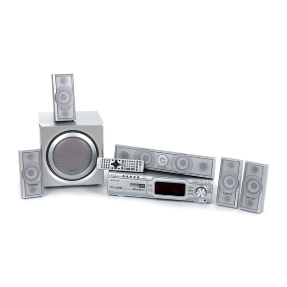
DVD Home Theater Sound System
SA-HT670PC
Color
(S).......................Silver Type
Frequency Range:
Sensitivity:
S/N 26dB
Antenna Terminal:
lAM tuner section
Frequency Range:
AM Sensitivity S/N 20dB at
1000kHz:
Phone Jack:
Terminal:
lDisc section
Discs played [8 cm (3") or 12 cm (5")]:
(1) DVD-RAM (DVD-VR compatible, JPEG formatted discs)
(2) DVD-Audio
(3) DVD-Video
(4) DVD-R (DVD-Video compatible)
(5) CD-Audio (CD-DA)
(6) Video CD
(7) SVCD (Conforming to IEC62107)
(8) CD-R/CD-RW (CD-DA, Video-CD, SVCD, MP3, WMA, JPEG
formatted discs)
(9) MP3/WMA
lMaximum number of recognizable audio and picture contents
and groups:
© 2004 Panasonic AVC Networks Singapore Pte.
Ltd. All rights reserved. Unauthorized copying and
distribution is a violation of law.
ORDER NO.MD0403129C1
A6
87.9-107.9MHz
(200kHz in step)
87.5-108.0MHz
(100kHz in step)
2.5µV (IHF)
2.2µV
75Ω (non balance)
520-1710kHz (10kHz in step)
560µV/m
Stereo 3.5mm (1/8") jack
4000 audio and picture
contents and 400 groups
Advertisement
Table of Contents

Related Manuals for Panasonic SA-HT670PC


Summary of Contents for Panasonic SA-HT670PC
- Page 1 4000 audio and picture contents and 400 groups © 2004 Panasonic AVC Networks Singapore Pte. Ltd. All rights reserved. Unauthorized copying and distribution is a violation of law.
-
Page 2: Table Of Contents
SA-HT670PC lCompatible compression rate: Component video output (480P/480I): 1 Vp-p (75 Ω) MP3: between 32 kbps and 320 kbps Y output level: 0.7 Vp-p (75 Ω) WMA: between 48 kbps and 320 kbps output level: 0.7 Vp-p (75 Ω) (10) JPEG output level: lExif Ver 2.1 JPEG Baseline files... - Page 3 SA-HT670PC 9 Handling Precautions for Optical Pickup Unit 12.3. DVD Self Diagnostic Function-Error Code 9.1. Cautions to Be Taken in Handling the Optical Pickup Unit 12.4. Last Error Code saved during NO PLAY 12.5. Service mode table 2 9.2. Cautions to Be Taken When Replacing the Optical Pickup 12.6.
-
Page 4: Safety Precautions
SA-HT670PC 1 Safety Precautions 1.1. GENERAL GUIDELINES 1. When servicing, observe the original lead dress. If a short circuit is found, replace all parts which have been overheated or damaged by the short circuit. 2. After servicing, see to it that all the protective devices such as insulation barriers, insulation papers shields are properly installed. -
Page 5: Before Repair And Adjustment
SA-HT670PC Caution Be sure no power is applied to the chassis or circuit, and observe all other safety precautions. 8. Minimize bodily motions when handling unpackaged replacement ES devices. (Otherwise harmless motion such as the brushing together of your clothes fabric or the lifting of your foot from a carpeted floor can generate static electricity (ESD)sufficient to damage an ES device). -
Page 6: Precaution Of Laser Diode
SA-HT670PC 5 Precaution of Laser Diode CAUTION: This unit utilizes a class 1 laser. Invisible laser radiation is emitted from the optical pickup lens. Wavelength: 662nm(DVD)/785nm(VCD/CD). Maximum output radiation power from pickup: 100µW/VDE When the unit is turned on: 1. Do not look directly into the pick up lens. -
Page 7: General Description
SA-HT670PC 7 General Description 7.1. Operating instructions... -
Page 8: Disc Information
SA-HT670PC 7.2. Disc information... -
Page 9: Accessories
SA-HT670PC 8 Accessories Speaker cables Remote control AC power supply cord AM loop antenna Antenna plug FM indoor antenna Video Cable... -
Page 10: Handling Precautions For Optical Pickup Unit
SA-HT670PC 9 Handling Precautions for Optical Pickup Unit The laser diode in the optical pickup unit may break down due to static electricity of clothes or human body. Use with caution to electrostatic breakdown when servicing and handling the laser diode. - Page 11 SA-HT670PC 9.3.2. Human body grounding 1. Use the anti-static wrist strap to discharge the static electricity form your body.
-
Page 12: Disassembling The Casing And Checking P.c.b.s
SA-HT670PC 10 Disassembling the Casing and Checking P.C.B.s 10.1. Disassembly Procedure 10.2. Major Parts and P.C.B. Positions... -
Page 13: Top Cabinet
SA-HT670PC 10.3. Top Cabinet 10.4. Front Panel 1. Unscrew the screws. 1. Remove the connectors. (CN6901, CN6904) 2. Unscrew the screws 3. Release the tabs. 2. Lift up & remove the top cabinet. 10.5. CR16D Mechanism Unit 1. Unscrew the screws. -
Page 14: Rear Panel
SA-HT670PC 10.6. Rear panel 10.8. Regulator P.C.B. 1. Remove the connector. (CN2013) 1. Unscrew the screws. 2. Remove the connector. (CN2007) 2. Unscrew the screws 3. Release the tabs. 10.9. AC Inlet P.C.B. & Transformer P.C.B. 1. Remove the connectors. (CN502, CN503) 10.7. -
Page 15: Power P.c.b
SA-HT670PC 10.11. FL P.C.B.,Selector P.C.B. and 5 Disc P.C.B. 1. Remove the volume knob. 2. Unscrew the screws.Remove the Volume knob and Mic knob. 10.10. Power P.C.B. 1. Unscrew the screws. -
Page 16: Assembling And Disassembling The Mechanism Unit
SA-HT670PC 11 Assembling and Disassembling the Mechanism unit 11.1. Replacement for DVD traverse 11.2. Replacement for optical deck pickup unit (CD mechanism) - Page 17 SA-HT670PC...
- Page 18 SA-HT670PC...
-
Page 19: Assembling For Traverse Motor And Spindle Motor
SA-HT670PC 11.3. Assembling for traverse motor and spindle motor... - Page 20 SA-HT670PC...
-
Page 21: Procedure For Removing Dvd Loading Mechanism
SA-HT670PC 11.4. Procedure for removing DVD loading mechanism 1. Turn off by pressing power SW in the body. 3. Disassemble the body, and take out DVD loading mechanism. 2. Unplug AC power cord after the indication of [GOOD-BYE], then disassemble the body. - Page 22 SA-HT670PC...
- Page 23 SA-HT670PC 11.5.3. Replacement for the traverse deck · Follow the (Step 1) - (Step 10) of item 11.5.2.
- Page 24 SA-HT670PC 11.5.4. Disassembly for DVD loading unit · Follow the (Step 1) - (Step 10) of item 11.5.2. · Follow the (Step 1) - (Step 4) of item 11.5.3.
- Page 25 SA-HT670PC...
- Page 26 SA-HT670PC...
-
Page 27: Cr16 Mechanism Assembly Procedure
SA-HT670PC 11.6. CR16 MECHANISM ASSEMBLY PROCEDURE The following specified greases and/or oil must be applied when some specific parts are changed. 1. Floil grease (VFK1298): The floil grease must be applied to tray, tray (L) and tray (R). 2. Hanarl oil (VFK1700): The hanarl oil must be applied to... - Page 28 SA-HT670PC...
- Page 29 SA-HT670PC...
- Page 30 SA-HT670PC...
- Page 31 SA-HT670PC...
- Page 32 SA-HT670PC...
- Page 33 SA-HT670PC...
- Page 34 SA-HT670PC...
- Page 35 SA-HT670PC...
- Page 36 SA-HT670PC...
- Page 37 SA-HT670PC...
- Page 38 SA-HT670PC...
-
Page 39: Disassembly For Traverse Mechanism
SA-HT670PC 11.7. Disassembly for traverse mechanism · Follow the (Step 1) - (Step 14) of Item 10. · Follow (Step 1) - (Step 7) described in Item 11.5. · Follow (Step 1) - (Step 7) described in Item 11.6. · Follow Step 1 described in Item 11.6. - Page 40 SA-HT670PC...
-
Page 41: Dvd-Optical Pick-Up Self-Diagnosis And Replacement Procedure
SA-HT670PC 12 DVD-Optical Pick-up Self-Diagnosis and Replacement Procedure 12.1. Optical Pickup Breakdown Diagnosis The optical pickup self-diagnosis function and tilt adjustment check function have been included in this unit. When repairing, use the following procedure for effective Self-diagnosis and tilt adjustment.Be sure to use the self-diagnosis functionbefore replacing the optical pickup when "NO DISC"... -
Page 42: Service Mode Table
SA-HT670PC 12.2. Service Mode Table 1 The service modes can be activated by pressing various button combination on the player and remote control unit. Player buttons Remote control unit buttons Application Note STOP Error code display (Refer to the item, “12.3. -
Page 43: Last Error Code Saved During No Play
SA-HT670PC Error Code Error Content Additional error explanation F890 Sending message when message is Sending message to AV task being sent to AV task F891 Message couldn’t be sent to AV task Begin sending message to AV task F893 FROM falsification... -
Page 44: Service Mode Table
SA-HT670PC 12.5. Service mode table 2 Pressing various button combinations on the player and remote control unit can activate the service modes. - Page 45 SA-HT670PC...
-
Page 46: Sales Demonstration Lock Function
SA-HT670PC 12.6. Sales demonstration lock function This function prevents discs from being lost when the unit is used for sales demonstrations by disabling the disc eject function. "LOCKED" is displayed on the unit, and ordinary operation is disabled. 12.6.1. Setting ·... -
Page 47: Self-Diagnosis Function
SA-HT670PC 13 Self-Diagnosis Function 13.2. Memorized Error Codes 13.2.1. Activating Self-Diagnosis Function 13.1. Automatic Displayed Error and Displaying Method Codes 1. Turn on the power. 13.1.1. Automatic Display Function 2. Select DVD/CD function. With no DVD/CD inserted in the player, press and hold down the button simultaneously For a power unit error, the code is automatically displayed. -
Page 48: Service Precautions
SA-HT670PC 14 Service Precautions 14.1. Recovery after the DVD player is repaired · When FROM or module P.C.B. is replaced, carry out the recovery processing to optimize the drive. Playback the recovery disk to process the recovery automatically. · Recovery disc (Product number: RFKZD03R005) ·... -
Page 49: Adjustment Procedure
SA-HT670PC 15 Adjustment Procedure 15.1. Service Tools and Equipment Application Name Number Tilt adjustment DVD test disc DVDT-S15 or DVDT-S01 Hex wrench Available on sales route. (T&) or RFKZ0185 Inspection Extension cable (Main P.C.B. to operation (R) P.C.B.) RFKZ0165 Extension cable (Module P.C.B. to Power P.C.B.) RFKZ0124 Extension cable (Module P.C.B. -
Page 50: Optical Adjustment
SA-HT670PC 15.4. Optical adjustment 15.4.1. Optical pickup tilt adjustment Measurement point Adjustment point Mode Disc Tangential adjustment screw T01 (inner periphery) play T30 DVDT-S15 or DVDT-S01 Tilt adjustment screw (center periphery) T43 (outer periphery) play Measuring equipment Adjustment value None (Main unit display for servicing is used.) Adjust to the minimum jitter value. - Page 51 SA-HT670PC...
-
Page 52: Abbreviations
SA-HT670PC 16 Abbreviations INITIAL/LOGO ABBREVIATIONS INITIAL/LOGO ABBREVIATIONS A0~UP ADDRESS ERROR TORQUE CONTROL ACLK AUDIO CLOCK ERROR TORQUE CONTROL AD0~UP ADDRESS BUS REFERENCE ADATA AUDIO PES PACKET DATA ENCSEL ENCODER SELECT ADDRESS LATCH ENABLE ETMCLK EXTERNAL M CLOCK (81MHz/40.5MHz) AMUTE AUDIO MUTE... - Page 53 SA-HT670PC INITIAL/LOGO ABBREVIATIONS INITIAL/LOGO ABBREVIATIONS READ ENABLE VBLANK V BLANKING RFENV RF ENVELOPE COLLECTOR POWER SUPPLY RF PHASE DIFFERENCE OUTPUT VOLTAGE (CD-ROM) REGISTER SELECT VCDCONT VIDEO CD CONTROL (TRACKING RSEL RF POLARITY SELECT BALANCE) RESET DRAIN POWER SUPPLY VOLTAGE RESERVE...
-
Page 54: Schematic Diagram Notes
SA-HT670PC 17 Schematic Diagram Notes · This schematic diagram may be modified at any time Caution! with the development of new technology. IC and LSI are sensitive to static electricity. Notes: Secondary trouble can be prevented by taking care during... -
Page 55: Block Diagram
SA-HT670PC 18 Block Diagram IC8001 IC8251 MN2DS0003APH C0GBG0000044 OPTICAL PICK UP UNIT TRACKING COIL/FOCUS COIL/TRAVERSE MOTOR DRIVE PHOTO DETECTOR VIN1 VOL4+ VIN2 VIN3 HEAD VIN4 LEVEL VOL4- SHIFT VIN8 BIAS1 VIN7 VIN6 TRV DRV VIN1 VIN5 PWM1 VOL3+ VIN10 TRAVERSE... - Page 56 SA-HT670PC IC8051 IC8001 IC8451 C3ABPG000068 MN2DS0003APH C0FBBK000036 AUDIO DAC 64M SDRAM OUTPUT AMP AND V OUT7 DVD MIX L LOW-PASS FILTER BCK IN SRCK LRC IN MEMORY MEMORY LRCK ADDRESS ADDRESS D IN1 V OUT8 DVD MIX R OUTPUT AMP AND...
- Page 57 SA-HT670PC TUNER PACK AM ANT FM ANT IC2006 MIXER C9ZB00000431 IF AMP VIDEO DRIVE COIL COIL RF AMP BUFFER BIAS 150K Y/PY/G CY IN 13.5MHz JK2001 CY OUT Y(RED) (FM) BIAS CY SAG 150K CB/PB/B CB IN 13.5MHz CB OUT...
- Page 58 SA-HT670PC IC2013 C0AABB000055 HEADPHONES AMP IC2011 C1BB00000845 (6)2 1(7) APS(INPUT SELECT/DIGITAL SOUND PROCESSOR/ELECTRONIC VOLUME/TONE) (5)3 Q2102 Q2201 TMF L TMF RB TMF LB MUTING (TMFR) (TMF RA) (TMF LA) MUTING CONTROL (L OUT2) L OUT1 JK2001 (60)59 (OUT FR) TONE...
- Page 59 SA-HT670PC SIGNAL LINES : MAIN SIGNAL LINE : AM SIGNAL LINE : DVD AUDIO SIGNAL LINE IC501 : FM SIGNAL LINE : AM OSC SIGNAL LINE : DVD VIDEO SIGNAL LINE RSN311W64B-P : FM OSC SIGNAL LINE : FM /AM SIGNAL LINE...
- Page 60 SA-HT670PC...
-
Page 61: Schematic Diagram
SA-HT670PC 19 Schematic Diagram SCHEMATIC DIAGRAM-1 DVD MODULE (IN/OUT) CIRCUIT : +B SIGNAL LINE : CD-DA SIGNAL LINE : MAIN SIGNAL LINE : DVD(VIDEO) SIGNAL LINE : DVD(AUDIO) SIGNAL LINE IC8271 Spindle Motor Drive SPINDLE MOTOR ASSY IC8251 Tracking Coil/Focus Coil/... - Page 62 SA-HT670PC SCHEMATIC DIAGRAM-2 DVD MODULE (DV2) CIRCUIT : +B SIGNAL LINE : CD-DA SIGNAL LINE : DVD(VIDEO) SIGNAL LINE : DVD(AUDIO) SIGNAL LINE IC8051 64M SDRAM IC8651 RFKFMH81T160 IC8611 (Not Supplied) EEPROM IC IC8001 DV2-1 LSI IC8605 IC8601 Reset IC...
- Page 63 SA-HT670PC SCHEMATIC DIAGRAM-3 MAIN CIRCUIT STANDING CIRCUIT : +B SIGNAL LINE : MAIN SIGNAL LINE : FM/AM SIGNAL LINE : DVD(VIDEO) SIGNAL LINE : - B SIGNAL LINE CN2004 CN2003 CP2001 CN2002 C2022 C2819 16V47 DVD STAT TUNER 0.022 DVD CMD...
- Page 64 SA-HT670PC SCHEMATIC DIAGRAM-4 MAIN CIRCUIT : MAIN SIGNAL LINE : +B SIGNAL LINE : - B SIGNAL LINE C2503 R2504 C2505 R2505 0.033 4.7K 50V1 R2619 2.2K R2514 R2512 C2512 C2504 R2508 R2620 R2308 0.22 1.8K 1.8K 1.8K C2173 R2176...
- Page 65 SA-HT670PC SCHEMATIC DIAGRAM-5 MAIN CIRCUIT REGULATOR CIRCUIT : +B SIGNAL LINE : MAIN SIGNAL LINE : DVD(VIDEO) SIGNAL LINE : - B SIGNAL LINE CN2008 KEY2 JOG B R2056 R2057 JOG A CIRCUIT R2058 (CN6901) R2042 R2040 VREF+ SCHEMATIC R2054...
- Page 66 SA-HT670PC SCHEMATIC DIAGRAM-6 POWER CIRCUIT : MAIN SIGNAL LINE AC INLET CIRCUIT : +B SIGNAL LINE IC501 Q516 C530 0.001 RSN311W64B-P R589 C555 KRC102MTA Power Amp IC 35V4.7 C551 C531 0.001 Switch 0.01 C532 0.001 DISP -VCC +VCC -VCC +VCC...
- Page 67 SA-HT670PC SCHEMATIC DIAGRAM-7 FL CIRCUIT : +B SIGNAL LINE : MAIN SIGNAL LINE FL6901 SELECTOR CIRCUIT HNA-14LM07T CN6900 H6902 H6903 R6928 R6929 R6930 R6931 R6932 4.7K 6.8K FLDA C6905 C6906 R6541 R6511 50V22 50V22 FLCLK FLCS D6908 D6525 R6933 C6939...
- Page 68 SA-HT670PC SCHEMATIC DIAGRAM-8 CD LOADING CIRCUIT : +B SIGNAL LINE IC11 C0GAG0000007 UP/DOWN MOTOR DRIVE 0.01 16V100 RM11 UP/DOWN MOTOR CHANGE BOTTOM OPEN B3NAA0000068 SENSOR +7.5V STOCK PGND CR16 SWITCH DNGD UP/DOWN F PLAY UP/DOWN R BOTTOM SW POSTION SENS...
-
Page 69: Printed Circuit Board Diagram
SA-HT670PC 20 Printed Circuit Board Diagram A A A A A A A A DVD MODULE P.C.B. (REP3654N) (SIDE:A) DVD MODULE P.C.B. (REP3654N) (SIDE:B) CP8252 C8254 TP8514 C8255 C8503 LB8502 CP8251 TP8515 TP8517 TP8500 TC8501 TC8502 R8501 TP8511 TP8520 TP8521... - Page 70 SA-HT670PC A A A A MAIN P.C.B. (REPX0418A) STANDING P.C.B. (REPX0418A) C2042 R2891 C2803 R2890 C2043 C2802 C2045 L2022 C2044 C2801 R2886 C2808 L2025 R2889 C2805 C2040 C2807 R2887 C2041 C2806 R2807 R2888 C2911 C2912 CN2000 C2046 R2127 C2047 C2907...
- Page 71 SA-HT670PC A A A A REGULATOR P.C.B. (REPX0418A) H2000 H2010 C2172 R2850 C2081 E2000 R2853 Q2011 C2056 Q2021 D2024 L2017 D2012 D2013 Q2015 R2826 Q2017 R2827 Q2013 R2828 Q2022 L2018 CN2007 Q2012 Q2023 R2829 D2027 R2830 Q2014...
- Page 72 SA-HT670PC A A A A POWER P.C.B. (REPX0424A) H504 Q523 R566 J514 SUB+B C575 E500 C540 R543 R597 CN501 R544 J419 C537 R540 R554 J515 R539 J513 R542 JK501 R541 J580 C541 R548 C550 R521 R522 R537 J415 R545 Q520...
- Page 73 SA-HT670PC A A A A SELECTOR P.C.B. (REPX0414A) R6929 S6911 S6910 S6909 S6908 S6907 R6932 R6931 R6930 R6928 PROGRESSIVE CD / TUNE MODE SKIP FORWARD SKIP BACKWORD S.F.C H6903 SENSOR CN6904 W6909 FL P.C.B. (REPX0414A) C6500 W6910 CN6901 CN6900 W6900...
- Page 74 SA-HT670PC A A A A CD LOADING P.C.B. (REP3569A) CHANGESW RM21 LOADING_MOTOR STOCKSW PLAYSW RM11 UPDOWN IC11 OPENSW BOTTOMSW...
-
Page 75: Wiring Connection Diagram
SA-HT670PC 21 Wiring Connection Diagram HEADPHONE JACK RM21 LOADING_MOTOR JK6901 RM11 UPDOWN CD LOADING P.C.B. FL P.C.B. H6902 VR6900 OPTICAL VOLUME PICKUP CN6900 CN6901 CN6904 H6903 SELECTOR P.C.B. TUNER PACK UNIT FP8501 5 DISC P.C.B. DVD MODULE P.C.B. (SIDE:A) STANDING P.C.B. - Page 76 SA-HT670PC...
-
Page 77: Illustration Of Ic 痴, Transistors And Diodes
SA-HT670PC 22 Illustration of IC’s, Transistors and Diodes C0FBBK000036 (48p) C3FBMD000134 C0AABB000055 KIA4558FEL (8p) C0HBB0000040 (48p) C0ABCB000052 (14p) C1BB00000845 (80p) C0CBCBD00018 (8p) C2CBHG000139 (100p) C0JBAR000292 (16p) MN2DS0003APH (256p) No.1 C3ABPG000068 (54p) C3EBGC000055 (8p) No.1 C9ZB00000431 (34p) C0GBF0000004 C0CBADG00023 C0EBE0000384 C0EBA0000031... -
Page 78: Terminal Function Of Ics
SA-HT670PC 23 Terminal Function of ICs 23.1. IC2018 (C2CBHG000139): Terminal Function Name Operation CPU SFC output (“L”:active) INH2 Analog switch enable signal output Terminal Function (“L”:active) Name PARTY PARTY signal output (“L”:active) ST SW Stock switch signal input Not used, open... -
Page 79: Parts Location And Replacement Parts List
SA-HT670PC 24 Parts Location and Replacement Parts List Notes: *Important safety notice: Components identified by mark have special characteristics important for safety. Furthermore, special parts which have purposes of fire-retardant (resistors), high-quality sound (capacitors), low-noise (resistors), etc. are used. When replacing any of components, be sure to use only manufacture’s specified parts shown in the parts list. -
Page 80: Loading Mechanism, Traverse Unit & Cabinet
SA-HT670PC 24.1. Loading Mechanism, Traverse Unit & Cabinet 24.1.1. Loading Mechanism, Traverse Unit & Cabinet Parts Location... - Page 81 SA-HT670PC...
- Page 82 SA-HT670PC...
- Page 83 SA-HT670PC...
- Page 84 SA-HT670PC...
- Page 85 SA-HT670PC...
- Page 86 SA-HT670PC 24.1.2. Traverse and Cabinet Parts List Ref. Part No. Part Name & Description Remarks RDG0535 UD SPEED DOWN GEAR Ref. Part No. Part Name & Description Remarks RDG0536 SELECT SPEED DOWN GE RDG0537-1 SELECT DRIVE GEAR RDG0538-1 CHANGE GEAR...
-
Page 87: Component Parts List
SA-HT670PC 24.2. Component Parts List Ref. Part No. Part Name & Description Remarks Ref. Part No. Part Name & Description Remarks Q516 KRC102MTA TRANSISTOR PRINTED CIRCUIT BOARD Q517 B1BACG000009 TRANSISTOR Q519 KTC3199GRTA TRANSISTOR REP3654N DVD MODULE P.C.B. Q520 B1GCCFJJ0015 TRANSISTOR... - Page 88 SA-HT670PC Ref. Part No. Part Name & Description Remarks Ref. Part No. Part Name & Description Remarks D513 B0HARM000017 DIODE LB8304 J0JCC0000119 CHIP INDUCTOR D514 B0HARM000017 DIODE LB8305 J0JCC0000119 CHIP INDUCTOR D515 B0EAKM000122 DIODE LB8401 D0GB151JA008 150 1/16W D516 B0EAKM000122...
- Page 89 SA-HT670PC Ref. Part No. Part Name & Description Remarks Ref. Part No. Part Name & Description Remarks CN2007 K1KA06A00008 6P SOCKET CN2008 K1MN10A00052 10P CONNECTOR FUSE HOLDERS CN2009 K1MN22A00027 22P FFC CONNECTOR CN2013 K1KA02A00008 CONNECTOR FC501 EYF52BC FUSE HOLDER CN6900...
- Page 90 SA-HT670PC Ref. Part No. Part Name & Description Remarks Ref. Part No. Part Name & Description Remarks W2062 ERJ6GEY0R00V 0 1/10W R558 ERDS1FVJ392T 3.9K 1/2W W2091 ERJ6GEY0R00V 0 1/10W R559 ERDS2TJ224T 220K 1/4W W2092 ERJ6GEY0R00V 0 1/10W R560 ERDS2TJ682T 6.8K 1/4W...
- Page 91 SA-HT670PC Ref. Part No. Part Name & Description Remarks Ref. Part No. Part Name & Description Remarks R2061 ERJ3GEYJ221V 220 1/16W R2161 D0GB333JA002 33K 1/16W R2062 ERJ3GEYJ221V 220 1/16W R2162 D0GB562JA002 5.6K 1/16W R2063 ERJ3GEYJ221V 220 1/16W R2163 ERJ3GEYJ102V 1K 1/16W...
- Page 92 SA-HT670PC Ref. Part No. Part Name & Description Remarks Ref. Part No. Part Name & Description Remarks R2301 D0GB332JA002 3.3K 1/16W R2816 D0GB392JA002 3.9K 1/16W R2302 ERJ3GEYJ103V 10K 1/16W R2818 D0GB272JA002 2.7K 1/16W R2303 D0GB393JA002 39K 1/16W R2819 D0GB1R0JA002 1 1/16W...
- Page 93 SA-HT670PC Ref. Part No. Part Name & Description Remarks Ref. Part No. Part Name & Description Remarks R6512 ERJ3GEYJ221V 220 1/16W R8325 ERJ3RBD161V 160 3W R6514 D0GB101JA002 100 1/16W R8326 ERJ3GEY0R00V 0 1/16W R6515 ERJ3GEYJ102V 1K 1/16W R8331 ERJ3RBD161V 160 3W...
- Page 94 SA-HT670PC Ref. Part No. Part Name & Description Remarks Ref. Part No. Part Name & Description Remarks C2007 ECUV1C104KBV 0.1 16V CAPACITORS C2008 ECUV1C104KBV 0.1 16V C2009 ECEA0JKA101B 100 6.3V F1D1E103A001 0.01 25V C2019 ECJ1VB1H331K 330P 50V F2A1C101A235 100 16V...
- Page 95 SA-HT670PC Ref. Part No. Part Name & Description Remarks Ref. Part No. Part Name & Description Remarks C2121 ECJ1VC1H151K 150P 50V C2249 ECJ1VB1A105K 1 10V C2122 ECJ1VB1H471K 470P 50V C2250 ECEA1HKA010B 1 50V C2123 ECEA1HKA100I 10 50V C2251 ECJ1VC1H101K 100P 50V...
- Page 96 SA-HT670PC Ref. Part No. Part Name & Description Remarks Ref. Part No. Part Name & Description Remarks C2810 ECJ1VB1H221K 220P 50V C8021 ECJ0EF1C104Z 0.1 16V C2811 ECJ1VB1E103K 0.01 25V C8022 ECJ1ZF1C104Z 0.1 16V C2812 ECJ1VB1E103K 0.01 25V C8023 F1H0J1050013 1 6.3V...
-
Page 97: Packing Materials & Accessories Parts List
SA-HT670PC Ref. Part No. Part Name & Description Remarks Ref. Part No. Part Name & Description Remarks C8307 ECJ1ZF1C104Z 0.1 16V C8550 EEE0JA330WR 33P 6.3V C8311 ECJ1ZF1C104Z 0.1 16V C8551 ECJ1ZF1C104Z 0.1 16V C8312 F1H0J1050013 1 6.3V C8552 EEEFC1C100R 0.P 16V... -
Page 98: Packaging
SA-HT670PC 24.4. Packaging...