
Related Manuals for Fujitsu MB95200 Series


Summary of Contents for Fujitsu MB95200 Series
- Page 1 Fujitsu Microelectronics (Shanghai) Co., Ltd. MCU-AN- 500018-E-11 Application Note F²MC-8FX FAMILY 8-BIT MICROCONTROLLER MB95200 SERIES HOW TO MAKE ON-BOARD DEBUG APPLICATION NOTE...
-
Page 2: Revision History
To obtain up-to-date information and/or specifications, contact your Fujitsu sales representative or Fujitsu authorized dealer. 2. Fujitsu will not be liable for infringement of copyright, industrial property right, or other rights of a third party caused by the use of information or drawings described in this manual. -
Page 3: Table Of Contents
How to make on board debug V1.1 Revision History Contents REVISION HISTORY ......................2 1 INTRODUCTION......................4 2 APPLICATION ENVIRONMENT ..................5 Debug Tool......................5 SOFTUNE ....................... 5 3 MCU PRODUCTS ......................6 4 HARDWARE DESIGN ..................... 7 Single Flash MCU Debugging Circuit ..............7 Dual Flash MCU Debugging Circuit ................. -
Page 4: Introduction
How to make on board debug V1.1 Chapter 1 Introduction 1 Introduction Debugging on the target board is a very important step in project design. This document will describe how to debug on a target board. The debugging interface described in this document can be used both as the in-circuit debugging tool and the in-circuit programming tool. -
Page 5: Application Environment
The version currently being used is F2MC-8L/8FX SOFTUNE Workbench V30L31, as shown below in the picture. It is available in the MB95200 MCU Starter Kit (PN: MB2146-410-01-E), or downloaded from Web: http: //www.fujitsu.com/cn/fmc/service/mcu/tools. Figure 2-2 SOFTUNE Version MCU-AN- 500018-E-11 – Page 5... -
Page 6: Mcu Products
How to make on board debug V1.1 Chapter 3 MCU Products 3 MCU Products This chapter introduces different models of MCU products. As the in-circuit debugging interface in the single flash MCU is different from that in the dual flash MCU, MCUs are classified into two categories in the list below. Series Flash Chip list... -
Page 7: Hardware Design
4 Hardware Design This chapter introduces the circuit of debugging interface. As the MB95200 series has two types of flash, i.e. single flash and dual flash, there are two types of debugging circuits corresponding to them. This chapter will introduce the two programming circuits. - Page 8 How to make on board debug V1.1 Chapter 4 Hardware Design If the MCU target needs a reset circuit, please design the reset circuit according to the diagram below. Target Board Figure 4-2 Debugging Connector and Reset Circuit for Single Flash MCU Pin 4 of the connector is used to connect to the reset circuit.
-
Page 9: Dual Flash Mcu Debugging Circuit
How to make on board debug V1.1 Chapter 4 Hardware Design 4.2 Dual Flash MCU Debugging Circuit Figure 4-3 shows the circuit diagram of the in-system debugging interface. To design the in- system debugging interface, three pins, UVCC_EV, GND and DBG, are needed. (Add pin RST_OUT if necessary.) Target Board Figure 4-3 Dual Flash MCU Debugging Circuit... -
Page 10: Debugging Operation
How to make on board debug V1.1 Chapter 5 Debugging Operation 5 Debugging Operation This chapter introduces debugging operation by F2MC-8L/8FX SOFTUNE. 5.1 Preparation before using F2MC-8L/8FX SOFTUNE (1) Connect the BGMA to a PC (2) Connect the EV-board to the BGMA (Note that user can only power on the MCU after connecting the target board to the BGM adaptor) -
Page 11: Debugging With F2Mc-8L/8Fx Softune
How to make on board debug V1.1 Chapter 5 Debugging Operation 5.2 Debugging with F2MC-8L/8FX SOFTUNE After the 3-step preparation introduced in chapter 5.1, user can start debugging as shown below. (1) Start debugging. (by clicking 'start debug' in the 'Debug' tag) Figure 5-3 Start Debugging MCU-AN- 500018-E-11 –... - Page 12 How to make on board debug V1.1 Chapter 5 Debugging Operation (2) Start Debugging (Code Update) Click “ D ebug ” → ” R un ” to start debugging or use the shortcut key as indicated in figure 5-5. Figure 5-4 Run Operation Figure 5-5 Shortcut Keys MCU-AN- 500018-E-11 –...
- Page 13 How to make on board debug V1.1 Chapter 5 Debugging Operation (3) Register Operation Select View “ → ” Register ” to open the register window. Then press the right button of the mouse to display a pop-up menu, select S etup to add/delete registers in the register “...
- Page 14 How to make on board debug V1.1 Chapter 5 Debugging Operation (5) Watch Operation Highlight the symbol to be watched and press the right button of the mouse. A menu pops up and selects “Watch” in the menu. Figure 5-8 Select the Watch Window Put the mouse pointer inside the window and press the right button to display a pop-up menu.
- Page 15 How to make on board debug V1.1 Chapter 5 Debugging Operation (6) Breakpoints Setting Set breakpoints by mouse-clicking the inside of the green circle in the code, as shown in the figure below. Click here to set/ reset break point Figure 5-10 Breakpoints Setting Method 1 Another way to set breakpoints is specifying the program address or data address by selecting “Debug”...
-
Page 16: Additional Information
How to make on board debug V1.1 Chapter 6 Additional Information 6 Additional Information For more information on FUJITSU MB95200 products, please visit following website: Simplified Chinese Version http://www.fujitsu.com/cn/fmc/services/mcu/mb95200/ English Version http://www.fujitsu.com/cn/fmc/en/services/mcu/mb95200/ MCU-AN- 500018-E-11 – Page 16... -
Page 17: Appendix
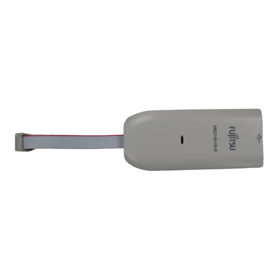
How to make on board debug V1.1 Chapter 7 Appendix 7 Appendix 7.1 Tables Table 3-1 MCU Products......................6 7.2 Figures Figure 2-1 BGM Adaptor ......................5 Figure 2-2 SOFTUNE Version....................5 Figure 4-1 Basic Connector Circuit for Single Flash MCU ............7 Figure 4-2 Debugging Connector and Reset Circuit for Single Flash MCU......