Table of Contents
Advertisement
Quick Links
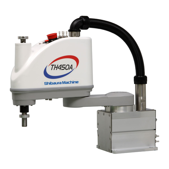
TH450A
TH550A/TS3000
INSTRUCTION MANUAL
TRANSPORTATION AND INSTALLATION MANUAL
1.
Make sure that this instruction manual is delivered to the final
user of Toshiba Machine's industrial robot.
2.
Before operating the industrial robot, read through and
completely understand this manual.
3.
After reading through this manual, keep it nearby for future
reference.
INDUSTRIAL ROBOT
Notice
February, 2010
TOSHIBA MACHINE CO., LTD.
NUMAZU, JAPAN
STE 80808–2
Advertisement
Table of Contents

Related Manuals for Toshiba TH450A


Summary of Contents for Toshiba TH450A
- Page 1 TRANSPORTATION AND INSTALLATION MANUAL Notice Make sure that this instruction manual is delivered to the final user of Toshiba Machine’s industrial robot. Before operating the industrial robot, read through and completely understand this manual. After reading through this manual, keep it nearby for future reference.
- Page 2 TRANSPORTATION AND INSTALLATION MANUAL Copyright 2009 by Toshiba Machine Co., Ltd. All rights reserved. No part of this document may be reproduced in any form without obtaining prior written permission from Toshiba Machine Co., Ltd. The information contained in this manual is subject to change without prior notice to effect improvements.
- Page 3 TRANSPORTATION AND INSTALLATION MANUAL Preface This manual describes the basic specifications of the industrial robot and controller, and how to unpack and install them. Specifically, it describes how to unpack the shipment containing the equipment, how to install the equipment, how to connect wiring and air piping, and how to attach tools.
- Page 4 TRANSPORTATION AND INSTALLATION MANUAL Precautions on Safety Important information on the robot and controller is noted in the instruction manual to prevent injury to the user and persons nearby, prevent damage to assets and to ensure correct use. Make sure that the following details (indications and symbols) are well understood before reading this manual.
- Page 5 • Always use the power voltage and power capacity designated Mandatory by Toshiba Machine. Failure to do so could lead to device faults or fires. • Always use the designated power cable. Using a cable other than that designated could lead to fires or faults.
- Page 6 TRANSPORTATION AND INSTALLATION MANUAL CAUTION • NEVER lift the robot by the arm 2 cover or arm 2. Doing so will apply an excessive force on the robot's mechanism section and could lead to faults. • For the controller, secure the ample space for air vent. Prohibited Heating of controller could lead to malfunction.
-
Page 7: Table Of Contents
TRANSPORTATION AND INSTALLATION MANUAL Table of Contents Page Specifications ......................11 Robot Configuration Diagram ................11 Name of Each Part ..................12 External Dimensions..................13 Specifications Table..................15 Transportation ......................16 Unpacking......................16 Transportation ....................18 2.2.1 Mass and Dimensions ...............18 2.2.2 Transporting the Robot..............19 2.2.3 Transporting the Controller..............22 Storage ......................23 2.3.1 Storage Precautions for the Robot ............23... - Page 8 TRANSPORTATION AND INSTALLATION MANUAL 4.1.2 Connecting the Power Cable “ACIN” of Fig. 4.1; plug connector attached)..........38 4.1.3 Connecting the Motor Cable “MOTOR” of Fig. 4.1) (Cable attached) ............39 4.1.4 Connecting the Encoder Cable “ENC” of Fig. 4.1) (Cable attached) ............40 4.1.5 Connecting the Robot Control Signal Cable “HAND”...
- Page 9 Page Fig. 1.1 Robot Configuration Diagram ................11 Fig. 1.2 Name of each part....................12 Fig. 1.3 External dimensions of the robot (TH450A) ............13 Fig. 1.4 External dimensions of the robot (TH550A) ............14 Fig. 2.1 Packaging state....................17 Fig. 2.2 Outer dimensions at transport (TH450A)............18 Fig.
- Page 10 .......................71 Fig. 5.10 Setting of maximum speed and acceleration/deceleration in relation to gravity center offset (Axes 1 and 2) (TH450A)..........72 Fig. 5.11 Setting of maximum speed and acceleration/deceleration in relation to gravity center offset (Axis 4) (TH450A) ............73 Fig.
-
Page 11: Specifications
Robot Configuration Diagram TSPC communication cable (obtained by customer) PC (obtained by customer) Program support software TSPC (option) TCPRGOS (option) TH450A/TH550A robot unit Cable between robot and Operation panel controller Split type (option) Teach pendant (option) TP cable Robot controller Fig. -
Page 12: Name Of Each Part
TRANSPORTATION AND INSTALLATION MANUAL Name of Each Part Fig. 1.2 shows the name of each part of the robot. The name of each part of the robot is common between the TH450A and TH550A. Axis 2 (rotation) Wiring panel Cover... -
Page 13: External Dimensions
Fig. 1.3 refers to the external dimensions of the robot. 4 × ø14 Hand-operated air Joint mounting holes 4 × ø4 tube Hand I/O connector Brake OFF switch About 350 Space for cable Fig. 1.3 External dimensions of the robot (TH450A) STE 80808 – 13 –... - Page 14 TRANSPORTATION AND INSTALLATION MANUAL 4 × ø14 Hand-operated air Joint 4 × ø4 tube mounting holes Hand I/O connector Brake OFF switch About 350 Space for cable Fig. 1.4 External dimensions of the robot (TH550A) STE 80808 – 14 –...
-
Page 15: Specifications Table
TRANSPORTATION AND INSTALLATION MANUAL Specifications Table Item Specifications Structure Horizontal multi-joint type SCARA robot Model TH450A TH550A Applicable controller TS3000 Mass of robot body 26 kg 28 kg No. of controlled axes Four (4) Arm length 450 mm 550 mm... -
Page 16: Transportation
TRANSPORTATION AND INSTALLATION MANUAL Transportation Unpacking The robot and controller are shipped separately in corrugated cardboards. Fig. 2.1 shows each packaging state. Open the packages in a location easily accessible, where the equipment is to be installed. Take careful precautions not to damage the robot and controller. After opening the packages, make sure that all the accessories are present and that nothing has been damaged during transport. - Page 17 If any parts of the equipment are found damaged or any accessories are missing after the shipment containing the robot and controller have reached your office, DO NOT install and operate them. Otherwise, the equipment will malfunction. Contact Toshiba Machine immediately. • Dispose of the wooden pallet, corrugated cardboards, polyethylene shipping bags and cushion material according to the customer’s in-house regulations.
-
Page 18: Transportation
The mass and outer dimensions of the robot are shown in Fig. 2.2 and Fig. 2.3. For the mass and outer dimensions of the controller, see Fig. 3.5 of Para. 3.3.1. Mass of robot body 26 kg Clamp Fig. 2.2 Outer dimensions at transport (TH450A) STE 80808 – 18 –... -
Page 19: Transporting The Robot
TRANSPORTATION AND INSTALLATION MANUAL Mass of robot body 28 kg Clamp Fig. 2.3 Outer dimensions at transport (TH550A) 2.2.2 Transporting the Robot In principle, the robot should be transported in the state shown in Fig. 2.2 and Fig. 2.3 above. Fold back and secure the arm with the attached clamp. (The robot is shipped in this posture. - Page 20 It is possible to lift up and transport the robot. Pass the wire through the attached eyebolt, then lift up the robot carefully, as shown in Fig. 2.4. The figure shows the TH450A. Wire Fig. 2.4 Lifting up the robot CAUTION •...
- Page 21 Handling areas (shaded areas) DO NOT hold the duct. DO NOT hold the ball screw spline shaft. The figure shows the TH450A. Fig. 2.5 Robot handling areas After the installation, remove the clamp and eyebolt used for transport. CAUTION •...
-
Page 22: Transporting The Controller
TRANSPORTATION AND INSTALLATION MANUAL 2.2.3 Transporting the Controller Disconnect all cables and teach pendant before transporting the controller. DANGER • When placing the controller on the floor, etc., make sure not to have your hands or feet caught. STE 80808 –... -
Page 23: Storage
TRANSPORTATION AND INSTALLATION MANUAL Storage Avoid storing the robot and controller for long periods of time after unpacking them. If this is unavoidable, however, strictly observe the following precautions for storage. 2.3.1 Storage Precautions for the Robot CAUTION • Secure the base completely to prevent the robot from falling over. When placed directly on the floor, the robot is unstable and will fall over. -
Page 24: Installation
0.98m/s or less Dust No inductive dust should exist. Consult with Toshiba Machine first if you wish to use the robot and controller in a dusty environment. No corrosive or combustible gas should exist. Sunlight The robot and controller should not be exposed to direct sunlight. -
Page 25: Robot Installation
TRANSPORTATION AND INSTALLATION MANUAL Robot Installation Before installing the robot, you should plan a layout, fully considering the working envelope (or operating range), coordinate system and space for maintenance. 3.2.1 External Dimensions External view drawing of the robot is shown in Fig. 3.1 and Fig. 3.2. 3.2.2 Working Envelope Fig. - Page 26 630 (Z-axis stroke at 300 mm) Standard Z-axis stroke (Z-axis stroke at 300 mm) Optional Z-axis stroke 2-axis operation range 2-axis operation range 1-axis operation range 1-axis operation range Fig. 3.1 External view and working envelope (TH450A) STE 80808 – 26 –...
- Page 27 TRANSPORTATION AND INSTALLATION MANUAL 630 (Z-axis stroke at 300 mm) Standard Z-axis stroke (Z-axis stroke at 300 mm) Optional Z-axis stroke 2-axis operation range 2-axis operation range 1-axis operation range 1-axis operation range Fig. 3.2 External view and working envelope (TH550A) STE 80808 –...
-
Page 28: Coordinate System
The robot's joint angle origin (0° or 0 mm position) is factory-calibrated according to the base reference planes. Fig. 3.3 shows the base coordinate system and origin of each axis joint angle. The coordinate system is common between the TH450A and TH550A. The figure shows the TH450A. - Page 29 TRANSPORTATION AND INSTALLATION MANUAL Reference plane Reference plane Axis 4 Axis 1 Axis 2 Axis 3 Origin of base coordinate system (when Z-axis stroke is 150 Origin of base coordinate system (when Z-axis stroke is 300 Fig. 3.3 Base coordinate system and joint angle origin STE 80808 –...
-
Page 30: Installing The Robot
TRANSPORTATION AND INSTALLATION MANUAL 3.2.4 Installing the Robot The robot is secured, using the mounting holes on the base (four (4) places). Use M12 hexagon socket head cap screws. The robot installation method is shown in Fig. 3.4. Reference planes are provided on the base unit. -
Page 31: Installing The Controller
TRANSPORTATION AND INSTALLATION MANUAL Installing the Controller 3.3.1 External Dimensions External view of the controller is shown in Fig. 3.5. Mass of controller: 13 kg Fig. 3.5 External view of controller STE 80808 – 31 –... -
Page 32: Precautions For Direct Installation
TRANSPORTATION AND INSTALLATION MANUAL 3.3.2 Precautions for Direct Installation It is necessary to provide a clearance of 50 mm or more in the horizontal direction and a clearance of 100 mm or more in the upward direction near the controller. CAUTION •... -
Page 33: Rack Mounting Dimensions
TRANSPORTATION AND INSTALLATION MANUAL 3.3.3 Rack Mounting Dimensions When mounting the robot controller in a rack, mount the side brackets using the screw holes provided on both ends of the front panel, and secure the controller to the rack. The side brackets in Fig. - Page 34 TRANSPORTATION AND INSTALLATION MANUAL As the cable connectors are connected to the rear side of the controller, provide a space of 110 mm or more on the rear side. For maintenance, the upper cover should be removed. (See Fig. 3.8.) Install the controller for enabling easy access to the controller when conducting maintenance.
-
Page 35: Precautions For Handling The Teach Pendant
TRANSPORTATION AND INSTALLATION MANUAL When the controller is mounted on the rack, the weight of the controller should be supported with the legs of the controller. Screw holes for rack-mounting the controller are used for securing the controller panel, and the weight of the controller cannot be supported only with these screws. -
Page 36: Safety Measures
TRANSPORTATION AND INSTALLATION MANUAL Safety Measures When installing the robot, provide sufficient space to carry out the work safely. Clarify the hazard zone, and provide a safety fence so that other persons cannot enter the zone easily. The hazard zone is the zone near the robot's working space where a hazardous state could occur if a person enters. -
Page 37: System Connections
TRANSPORTATION AND INSTALLATION MANUAL System Connections Cable Wiring This section describes the various types of cables and connectors and explains how these are to be connected. 4.1.1 Connector Arrangement on the Controller The cables connected to the robot controller are shown in Fig. 4.1. Fig. -
Page 38: Connecting The Power Cable "Acin" ( Of Fig. 4.1; Plug Connector Attached)
TRANSPORTATION AND INSTALLATION MANUAL External operation input signal cables (OUTPUT) Brake signal cable (BRK) Distribution I/O cable (EXT-I/O) In the subsequent paragraphs, we explain how to connect cables inclusive. For information on how to connect cables , refer to the Interface Manual. 4.1.2 Connecting the Power Cable “ACIN”... -
Page 39: Connecting The Motor Cable "Motor" ( Of Fig. 4.1) (Cable Attached)
TRANSPORTATION AND INSTALLATION MANUAL DANGER • Be sure to use the designated wire. Failure to do so could lead to fires or faults. • When connecting the connector and wires, make sure not to mistake the terminal arrangement. • After making the connection, use a tester, etc., to confirm the connection. For the terminal arrangement, see Para. -
Page 40: Connecting The Encoder Cable "Enc" ( Of Fig. 4.1) (Cable Attached)
TRANSPORTATION AND INSTALLATION MANUAL Connect to MOTOR, HAND, ENC, BRK. Fig. 4.2 Robot side connector arrangement 4.1.4 Connecting the Encoder Cable “ENC” of Fig. 4.1) (Cable attached) The encoder cable is a signal line used to transmit a signal from the rotation angle detecting encoder of each robot axis to the controller. -
Page 41: Connecting The Brake Signal Cable "Brk
TRANSPORTATION AND INSTALLATION MANUAL 4.1.6 Connecting the Brake Signal Cable “BRK” of Fig. 4.1) (Cable attached) The brake signal cable is used for motor brake ON and OFF. The connector for connecting the brake signal cable is BRK ( of Fig. 4.1). The connector for connecting the brake signal cable on the robot side is located at Fig. - Page 42 TRANSPORTATION AND INSTALLATION MANUAL Square connectors: ENC, HAND, SYSTEM, INPUT, OUTPUT, TRIG, CONV Firstly, completely insert the cable side connector into the controller connector. Then tighten the lock screws on both ends of the cable side connector with a screwdriver. A loose screw can cause a contact failure or other accident. To avoid this, make sure that the screws are clamped completely.
-
Page 43: Examples Of Connector Terminal Arrangement
TRANSPORTATION AND INSTALLATION MANUAL 4.1.8 Examples of Connector Terminal Arrangement Power cable connector ACIN Connects to controller. Type: JL04V–2E18–10PE–B DANGER Manufacturer: • Completely connect the Japan Aviation grounding cable. Electronics Industry Otherwise, an electric shock or fire may be Single phase, 200 - 240 VAC, caused if a fault or 50/60 Hz electric leak occurred. - Page 44 TRANSPORTATION AND INSTALLATION MANUAL General-purpose input signal cable connector INPUT Connects to controller. 17 16 15 14 13 12 11 Type: DHA-RC36-R132N-FA 28 27 26 25 24 23 22 21 20 19 36 35 34 33 32 31 30 29 Manufacturer: DDK General-purpose output signal cable connector OUTPUT Connects to controller.
- Page 45 TRANSPORTATION AND INSTALLATION MANUAL j) Emergency stop, safety input, and external P24V supply connector EMS Connects to controller. Type: ML-4000CWJH-10PGY 10 9 8 Manufacturer: SATO PARTS k) Brake connector BRK Connects to controller. Type: 1-1827876-6 A1 A2 A3 A4 A5 A6 Manufacturer: Tyco Electronics AMP STE 80808 –...
-
Page 46: Controller Connector Signals
TRANSPORTATION AND INSTALLATION MANUAL Controller Connector Signals 4.2.1 Connector Signal Connection Diagrams Diagrams showing which signals correspond to which terminals are shown in Section 2 of the Interface Manual. 4.2.2 Jumpers for Safety Related Signals The following system input signals are provided to serve for the safety purpose. System input signals SYSTEM-12 (STOP) - Page 47 TRANSPORTATION AND INSTALLATION MANUAL CAUTION • Unless the signals of SVOFF and emergency stop contacts 1, 2 are jumpered, the controller servo power cannot be turned on. • Unless the CYCLE signal is jumpered, the controller enters the cycle operation mode.
-
Page 48: Separating Control Panel From Controller
TRANSPORTATION AND INSTALLATION MANUAL Separating Control Panel from Controller 4.3.1 Removing Control Panel Remove the control panel in the following manner. Loosen the four (4) screws at the four (4) corners, which secure the control panel. Remove these screws, then carefully draw out the control panel toward your side. Caution: Be careful of the cable connected on the rear side. -
Page 49: Control Panel Mounting Dimensions
TRANSPORTATION AND INSTALLATION MANUAL 4.3.3 Control Panel Mounting Dimensions The dimensions of mounting the control panel are shown in Fig. 4.6. Cross truss head screws (ø3 × 6, ZN3–B) are used. 4-M3 Fig. 4.6 Control panel mounting dimensions STE 80808 –... -
Page 50: Mounting Dummy Panel On Controller
TRANSPORTATION AND INSTALLATION MANUAL 4.3.4 Mounting Dummy Panel on Controller When the control panel has been disengaged from the controller, mount a dummy panel on the place where the control panel was set before, as shown in Fig. 4.7. The dummy panel, mounting parts, etc. -
Page 51: Dimensions When Separating Control Panel
TRANSPORTATION AND INSTALLATION MANUAL 4.3.5 Dimensions when Separating Control Panel Fig. 4.8 shows the connections of the control panel and dummy panel. Provide a clearance of 50 mm or more (with cover, 60 mm or more) on the rear side of the separated control panel. -
Page 52: Tool Interface
TRANSPORTATION AND INSTALLATION MANUAL Tool Interface Mounting Tool The tool is mounted on the end of the tool shaft. Dimensions of the tool shaft section are shown in Fig. 5.1. As shown in Fig. 5.1, the tool is centered with the ø12H7 mating section. The tool direction is adjusted by means of the 4 ×... -
Page 53: Tool Wiring And Piping
TRANSPORTATION AND INSTALLATION MANUAL Tool Wiring and Piping The robot is provided with wiring and air piping for the tool. These wiring and piping extend to the arm 2 and are used as follows: 5.2.1 Tool Signals (Controller Side) The controller is provided with tool signals (i.e., eight (8) input signals for sensor, etc., eight (8) control signals for solenoid valve, etc., 24 VDC(P24V)... - Page 54 TRANSPORTATION AND INSTALLATION MANUAL a-2) Input signal connector HAND (Type P) Signal Input circuit and example of Signal name connections Input D-IN0 signal 0 Customer's side Input TS3000 D-IN1 signal 1 P24V Input D-IN2 signal 2 Input D-IN3 signal 3 ●...
- Page 55 TRANSPORTATION AND INSTALLATION MANUAL b-1) Output signal connector HAND (Type N) Output circuit and example of Signal name Signal No. connections Output D-OUT0 signal 0 Customer's Output D-OUT1 side signal 1 P24V Output DC relay D-OUT2 signal 2 Output D-OUT3 signal 3 Output D-OUT...
- Page 56 TRANSPORTATION AND INSTALLATION MANUAL b-2) Output signal connector HAND (Type P) Output circuit and example of Signal name Signal No. connections Output D-OUT0 signal 0 Customer's Output side D-OUT1 signal 1 P24V Output D-OUT2 signal 2 DC relay Output D-OUT D-OUT3 signal 3 Output...
-
Page 57: Tool Wiring
TRANSPORTATION AND INSTALLATION MANUAL 5.2.2 Tool Wiring Eight (8) input signals are provided for sensors, etc. and eight (8) control signals for solenoid valves, etc. A supply power signal of P24V is also provided. They are connected to the controller. The wiring arrangement for these cables is shown in Fig. 5.2. - Page 58 TRANSPORTATION AND INSTALLATION MANUAL JOFP JOFS JOEP JOES From sequencer etc. Grommet Cable inlet: Inner dia. 17 mm JOES JOFS Disconnect. 11 mm Fig. 5.2 Wiring to sequencer, etc. Input/output signal connector CN0 ( Type-N ) Input/output circuit Signal name Signal No.
- Page 59 TRANSPORTATION AND INSTALLATION MANUAL Input/output circuit Signal name Signal No. (Cannon) and example of connections Plus common (X8GI) D-OUT2 Output signal 2 DC relay drive Customer's side D-OUT3 Output signal 3 P24V D-OUT4 Output signal 4 D-OUT5 Output signal 5 DC relay D-OUT6 Output signal 6...
- Page 60 TRANSPORTATION AND INSTALLATION MANUAL CN0 hand connector 4 × ø4 Quick-operated joint for hand JOFP JOFS JOEP JOES JOEP JOFP Hand JOES JOFS 4 × ø4 air tube 4 × ø4 Quick-operated joint for hand Fig. 5.3 Tool wiring CAUTION •...
- Page 61 TRANSPORTATION AND INSTALLATION MANUAL Fig. 5.4 Tool wiring ( Type-N ) STE 80808 – 61 –...
- Page 62 TRANSPORTATION AND INSTALLATION MANUAL Fig. 5.4-A Tool wiring ( Type-P ) STE 80808 – 61 A–...
- Page 63 TRANSPORTATION AND INSTALLATION MANUAL Tool connection by using the hollow hole (14 mm-dia.) on Z-axis ball screw shaft. Connect the wiring while being careful about the edge Fig. 5.5 Wiring method STE 80808 – 62 –...
- Page 64 TRANSPORTATION AND INSTALLATION MANUAL Fixed stay (To be provided by customer.) Tool connection by attaching the fixed stays to the lower side of the arm. Fig. 5.6 Wiring method Note: For the tap holes on the lower side of the arm 2, which are used to attach the fixed stays, it is recommended to machine surfaces A in the figure above.
- Page 65 TRANSPORTATION AND INSTALLATION MANUAL CAUTION • Be sure to use a highly flexible robot cable, which should be secured below the arm with a cable clamp, etc. Unless a robot cable is used, the wire may be broken. • When performing tool wiring and piping, take all necessary measures against breakage due to rub, etc.
-
Page 66: Tool Air Piping
TRANSPORTATION AND INSTALLATION MANUAL The air tube is identified by the number and color. At piping, make sure that each tube is connected properly, referring to the below-mentioned. 1 : Red 2 : White 3 : Blue 4 : Yellow Panel air joint pitch dimensions Fig. -
Page 67: Permissible Load Conditions And Program Setting
TRANSPORTATION AND INSTALLATION MANUAL Permissible Load Conditions and Program Setting This paragraph describes the permissible load conditions of the robot and how to set up the program according to the load. 5.3.1 Permissible Load Conditions The robot load conditions are defined by the tool mass, moment of inertia and offset value of tool gravity center from the center of the tool shaft, as shown in Fig. - Page 68 TRANSPORTATION AND INSTALLATION MANUAL Tool gravity center Robot arm Moment of inertia Tool Offset value of gravity center Fig. 5.8 Robot tool 5.3.2 Load Conditions and Program Setting This robot can automatically change the maximum speed, acceleration/deceleration and servo gain by using the PAYLOAD command in the program according to the load conditions.
- Page 69 TRANSPORTATION AND INSTALLATION MANUAL • The servo gain of each robot axis is automatically changed according to the set load conditions. Program examples Basic program examples using the PAYLOAD command are shown below. For further information, see the Robot Language Manual. (Program example 1) The robot is moved under the load conditions of 5 kg mass and 100 mm gravity center offset.
-
Page 70: Setting Maximum Speed And Robot Acceleration/Deceleration For Load Conditions
TRANSPORTATION AND INSTALLATION MANUAL PAYLOAD={1,30} MOVE P2+POINT(0,0,100) GOTO LOOP FIN: MOVE P0 DOUT(1) STOP Setting of PAYLOAD command In the default state, or when the PAYLOAD command is not used, the maximum speed and acceleration/deceleration are set to 100% and the servo gain is set to the value under the minimum load. - Page 71 The maximum speed and acceleration/deceleration change with the load mass, as shown in Fig. 5.9. The settings of the maximum speed and acceleration/deceleration are common between the TH450A and TH550A. STE 80808 – 70 –...
- Page 72 TRANSPORTATION AND INSTALLATION MANUAL Acceleration/ Acceleration/ Deceleration Deceleration Maximum speed Maximum speed Load (kg) Load (kg) Setting of maximum speed and Setting of maximum speed and acceleration/deceleration in relation to acceleration/deceleration in relation to load mass (Axis 1) load mass (Axis 2) Acceleration/ Acceleration/ Deceleration...
- Page 73 Fig. 5.10, Fig. 5.11, Fig. 5.12 and Fig. 5.13. For the axis 3, however, no restriction is imposed on the offset. The settings are different between the TH450A and TH550A. Load mass ≤ 3 (kg) Load mass ≤...
- Page 74 Setting of acceleration/deceleration in Setting of maximum speed in relation to relation to offset (Axis 4) offset (Axis 4) Fig. 5.11 Setting of maximum speed and acceleration/deceleration in relation to gravity center offset (Axis 4) (TH450A) STE 80808 – 73 –...
- Page 75 TRANSPORTATION AND INSTALLATION MANUAL Load mass ≤ 3 (kg) Load mass ≤ 3 (kg) 3 (kg) < Load mass ≤ 5 (kg) 3 (kg) < Load mass ≤ 5 (kg) Load mass > 5 (kg) Load mass > 5 (kg) Offset (mm) Offset (mm) Setting of acceleration/deceleration in...
- Page 76 TRANSPORTATION AND INSTALLATION MANUAL Load mass ≤ 3 (kg) Load mass ≤ 3 (kg) 3 (kg) < Load mass ≤ 5 (kg) 3 (kg) < Load mass ≤ 5 (kg) Load mass > 5 (kg) Load mass > 5 (kg) Offset (mm) Offset (mm) Setting of acceleration/deceleration in...