
Related Manuals for Siemens RUGGEDCOM RX1524


Summary of Contents for Siemens RUGGEDCOM RX1524
- Page 1 Installation Manual SIMATIC NET Rugged Multi Service Platforms RUGGEDCOM RX1524 Edition 04/2021 https://www.siemens.com...
- Page 2 Preface Introduction Installing the Device SIMATIC NET Device Management Rugged Multi Service Platforms RUGGEDCOM RX1524 Modules Technical Specifications Installation Manual Certification 04/2021 C79000-G8976-1487-02...
- Page 3 Note the following: WARNING Siemens products may only be used for the applications described in the catalog and in the relevant technical documentation. If products and components from other manufacturers are used, these must be recommended or approved by Siemens. Proper transport, storage, installation, assembly, commissioning, operation and maintenance are required to ensure that the products operate safely and without any problems.
-
Page 4: Table Of Contents
Accessing Documentation ....................... v Registered Trademarks ......................v Warranty ..........................vi Training ..........................vi Customer Support ........................vi Contacting Siemens ....................... vii Introduction ........................... 1 Feature Highlights ....................1 Description ......................1 Required Tools and Materials ................. 2 Decommissioning and Disposal ................3 Cabling Recommendations .................. - Page 5 European Union (EU) ..................49 6.1.3 FCC ........................51 6.1.4 FDA/CDRH ......................51 6.1.5 ISED ........................51 6.1.6 ISO ........................51 6.1.7 RoHS ........................51 6.1.8 Other Approvals ....................52 EMC and Environmental Type Tests ..............52 RUGGEDCOM RX1524 Installation Manual, 04/2021, C79000-G8976-1487-02...
-
Page 6: Preface
Preface This guide describes the RUGGEDCOM RX1524. It describes the major features of the device, installation, commissioning and important technical specifications. It is intended for use by network technical support personnel who are responsible for the installation, commissioning and maintenance of the device. It is also recommended for use by network and system planners, system programmers, and line technicians. -
Page 7: Warranty
Preface Warranty Warranty Siemens warrants this product for a period of five (5) years from the date of purchase, conditional upon the return to factory for maintenance during the warranty term. This product contains no user-serviceable parts. Attempted service by unauthorized personnel shall render all warranties null and void. -
Page 8: Contacting Siemens
Call a local hotline center to submit a Support Request (SR). To locate a local hotline center, visit https://w3.siemens.com/aspa_app/?lang=en. Mobile App Install the Industry Online Support app by Siemens AG on any Android, Apple iOS or Windows mobile device and be able to: •... - Page 9 Preface Contacting Siemens viii RUGGEDCOM RX1524 Installation Manual, 04/2021, C79000-G8976-1487-02...
-
Page 10: Introduction
(EMI) and heavy electrical surges typical of the harsh environments found in many industrial applications. An operating temperature range of -40 to 85 °C (-40 to 185 °F) allows the RUGGEDCOM RX1524 to be placed in almost any location. -
Page 11: Required Tools And Materials
• Green = Alarms cleared/acknowledged • Red = Alarm Required Tools and Materials The following tools and materials are required to install the RUGGEDCOM RX1524: Tools/Materials Purpose AC/DC power cord (16 AWG) For connecting power to the device. RUGGEDCOM RX1524... -
Page 12: Decommissioning And Disposal
Recycling and disposal must be done in accordance with local regulations. Cabling Recommendations Siemens recommends using SIMATIC NET industrial Ethernet shielded cables for all Ethernet ports. 1.5.1 Protection On Twisted-Pair Data Ports... -
Page 13: Gigabit Ethernet 1000Base-Tx Cabling Recommendations
Siemens also does not recommend using copper Ethernet ports to interface with devices in the field across distances that could produce high levels of ground potential rise (i.e. greater than 2500 V), during line-to-ground fault conditions. -
Page 14: Installing The Device
The surface of the device may be hot during operation, or as a result of the ambient air temperature. Wear appropriate personal protective equipment and use caution when working with or around the device. RUGGEDCOM RX1524 Installation Manual, 04/2021, C79000-G8976-1487-02... -
Page 15: General Procedure
This product contains no user-serviceable parts. Attempted service by unauthorized personnel shall render all warranties null and void. Changes or modifications not expressly approved by Siemens AG could invalidate specifications, test results, and agency approvals, and void the user's authority to operate the equipment. -
Page 16: Mounting The Device
"Dimension Drawings (Page 44)". 2.3.1 Mounting the Device to a Rack For rack mount installations, the RUGGEDCOM RX1524 can be equipped with rack mount adapters pre-installed at the front or rear of the chassis. Additional adapters are provided for added stability. NOTICE Vibration hazard –... -
Page 17: Mounting The Device On A Din Rail
2.3.2 Mounting the Device on a DIN Rail For DIN rail installations, the RUGGEDCOM RX1524 can be equipped with panel/DIN rail adapters pre-installed on each side of the chassis. The adapters allow the device to be slid onto a standard 35 mm (1.4 in) DIN rail. -
Page 18: Mounting The Device To A Panel
2.3.3 Mounting the Device to a Panel For panel installations, the RUGGEDCOM RX1524 can be equipped with panel/DIN rail adapters pre-installed on each side of the chassis. The adapters allow the device to be attached to a panel using screws. -
Page 19: Connecting The Failsafe Alarm Relay
NO contact and closes the NC (Normally Closed) contact. Note Control of the failsafe relay output is configurable through RUGGEDCOM RX1524 . One common application for this relay is to signal an alarm if a power failure occurs. -
Page 20: Connecting Power
For 125/250 VDC rated equipment, an appropriately rated DC circuit breaker must be installed. • It is recommended to provide a separate 20 A circuit breaker for each power module module. • Equipment must be installed according to applicable local wiring codes and standards. RUGGEDCOM RX1524 Installation Manual, 04/2021, C79000-G8976-1487-02... -
Page 21: Connecting High Ac/Dc Power
NOTICE Electrical hazard – risk of damage to equipment Do not connect AC power cables to a 12, 24 or 48 VDC power supply terminal block. Damage to the power supply may occur. RUGGEDCOM RX1524 Installation Manual, 04/2021, C79000-G8976-1487-02... - Page 22 Ground Terminal Negative/Neutral (-/N) Terminal Figure 2.5 AC Terminal Block Wiring – European-style (Euroblock) Terminal Block for HIP Power Supplies Not Connected Removable Screw Terminal Block Non-removable Screw Terminal Block Positive/Live (+/L) Terminal Ground Terminal RUGGEDCOM RX1524 Installation Manual, 04/2021, C79000-G8976-1487-02...
- Page 23 For screw terminal blocks, install the safety cover. Screw Safety Cover Screw Terminal Block RUGGEDCOM RX1524 Device Figure 2.7 Assembling the Safety Cover Using a braided wire or other appropriate grounding wire, connect the ground terminal to the chassis ground connection.
-
Page 24: Connecting Low Dc Power
Do not connect AC power cables to a 12, 24 or 48 VDC power supply terminal block. Damage to the power supply may occur. Note The RUGGEDCOM RX1524 works with both positive VDC power supplies and negative VDC power supplies. RUGGEDCOM RX1524... - Page 25 Ground Terminal Figure 2.9 DC Terminal Block Wiring – European-style (Euroblock) Terminal Block for 12P, 24P and 48P Power Supplies Not Connected Removable Screw Terminal Block Non-removable Screw Terminal Block Positive (+) Terminal Negative (-) Terminal RUGGEDCOM RX1524 Installation Manual, 04/2021, C79000-G8976-1487-02...
- Page 26 Ground Terminal Figure 2.11 DC Terminal Block Wiring – European-style (Euroblock) Terminal Block for -12P, -24P and -48P Power Supplies Not Connected Removable Screw Terminal Block Non-removable Screw Terminal Block Positive (+) Terminal Negative (-) Terminal RUGGEDCOM RX1524 Installation Manual, 04/2021, C79000-G8976-1487-02...
- Page 27 Connect the negative wire from the power source to the negative (-) terminal on the terminal block. For screw terminal blocks, install the safety cover. Screw Safety Cover Screw Terminal Block RUGGEDCOM RX1524 Device Figure 2.13 Assembling the Safety Cover RUGGEDCOM RX1524 Installation Manual, 04/2021, C79000-G8976-1487-02...
- Page 28 #10 Ring Lug #10-32 Screw Connection from External Power Source Ground Connection Figure 2.14 Ground Connection Install the safety cover over the terminal block. This is mandatory for 48 VDC and -48 VDC power supplies. RUGGEDCOM RX1524 Installation Manual, 04/2021, C79000-G8976-1487-02...
- Page 29 Installing the Device 2.5.2 Connecting Low DC Power RUGGEDCOM RX1524 Installation Manual, 04/2021, C79000-G8976-1487-02...
-
Page 30: Device Management
This section describes how to connect to and manage the device. Connecting to the Device The following describes the various methods for accessing the RUGGEDCOM RX1524 console and Web interfaces on the device. For more detailed instructions, refer to the RUGGEDCOM ROX Configuration Manual for the RUGGEDCOM RX1524. - Page 31 Connect any of the available Ethernet ports on the device to a management switch and access the RUGGEDCOM RX1524 console and Web interfaces via the device's IP address. The factory default IP address for the RUGGEDCOM RX1524 is https://192.168.0.2. For more information about available ports, refer to "Modules (Page...
-
Page 32: Configuring The Device
Configuring the Device Once the device is installed and connected to the network, it must be configured. All configuration management is done via the RUGGEDCOM RX1524 interface. For more information about configuring the device, refer to the RUGGEDCOM ROX Configuration Manual associated with the installed software release. - Page 33 Device Management 3.2 Configuring the Device RUGGEDCOM RX1524 Installation Manual, 04/2021, C79000-G8976-1487-02...
-
Page 34: Modules
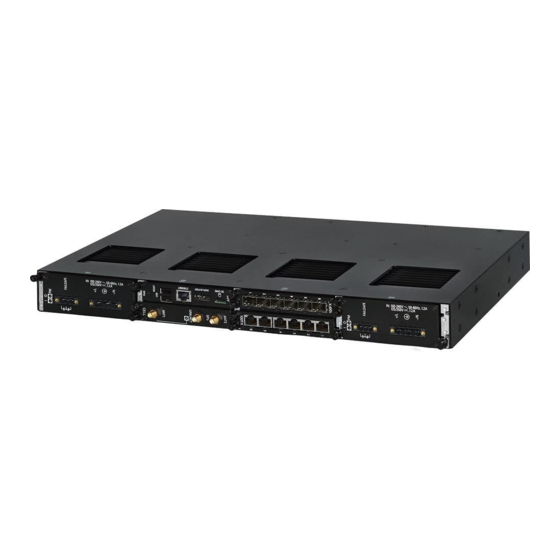
Modules The RUGGEDCOM RX1524 features slots for up to four field-replaceable line modules, which can be used to expand and customize the capabilities of the device to suit specific applications. A variety of modules are available, each featuring a specific type of communication port: copper Ethernet, fiber optic Ethernet, SFP, WAN, cellular modem and DDS. - Page 35 Input Range: 13 to 36 6GK6015-0AL11-0AA0 (Standard) Terminal Type: 6GK6015-0AL11-0AA1 Removable Screw (Conformal Coated) RUGGEDCOM RX1500PN PS 24P Specifications Article Numbers Input Range: 13 to 36 6GK6015-0AL14-0AA0 (Standard) Terminal Type: 6GK6015-0AL14-0AA1 European-style (Conformal Coated) (Euroblock) RUGGEDCOM RX1524 Installation Manual, 04/2021, C79000-G8976-1487-02...
- Page 36 RUGGEDCOM RX1500PN PS HI (shipped from Specifications Article Numbers 2019 on) Input Range: 88 to 300 6GK6015-0AL13-0AA0 VDC or 85 to 264 VAC (Standard) Terminal Type: 6GK6015-0AL13-0AA1 Removable Screw (Conformal Coated) RUGGEDCOM RX1500PN PS HIP Specifications Article Numbers RUGGEDCOM RX1524 Installation Manual, 04/2021, C79000-G8976-1487-02...
- Page 37 Power Consumption: 4 RUGGEDCOM RX1500PN LM X CG04 Specifications Article Numbers Ports: 2 6GK6015-0AL20-0PH0 (Standard) Speed: 1000 Mbps 6GK6015-0AL20-0PH1 Interface: TX (Conformal Coated) Port Type: M12 (8-pin, X-Coded) Distance: 100 m (328 ft) Power Consumption: 4 RUGGEDCOM RX1524 Installation Manual, 04/2021, C79000-G8976-1487-02...
- Page 38 Power Consumption: 5 RUGGEDCOM RX1500PN LM 4TX04B Specifications Article Numbers Ports: 4 6GK6015-0AL20-0PG0 (Standard) Speed: 100 Mbps 6GK6015-0AL20-0PG1 Interface: TX (Conformal Coated) Port Type: M12 (4-Pin, A-Coded, Controlled Bypass) Distance: 100 m (328 ft) RUGGEDCOM RX1524 Installation Manual, 04/2021, C79000-G8976-1487-02...
- Page 39 Mode: SM 6GK6015-0AL20-0EC0 (Standard) Speed: 1000 Mbps 6GK6015-0AL20-0EC1 Interface: LX (Conformal Coated) Wavelength: 820 nm Ports: 4 Port Type: LC Distance: 10 km (6.2 Power Consumption: 5 RUGGEDCOM RX1500PN LM FG50 Specifications Article Numbers RUGGEDCOM RX1524 Installation Manual, 04/2021, C79000-G8976-1487-02...
- Page 40 (Conformal Coated) RUGGEDCOM RX1500PN LM 6FX51 Specifications Article Numbers Mode: MM 6GK6015-0AL20-0BK0 (Standard) Speed: 100 Mbps 6GK6015-0AL20-0BK1 Interface: FX (Conformal Coated) Wavelength: 1310 nm Ports: 6 Port Type: LC Distance: 2 km (1.2 mi) RUGGEDCOM RX1524 Installation Manual, 04/2021, C79000-G8976-1487-02...
- Page 41 Antennas: 1 x LTE Main, 1 x LTE MIMO, 1 x GPS SIM: Dual Mini-SIM (2FF) Power Consumption: 7 RUGGEDCOM RX1500PN LM W51 Specifications Article Numbers Services: 4G LTE/HSPA+/ 6GK6015-0AL20-0WH0 HSDPA/HSUPA/DC-HSAP (Standard) +/UMTS/WDCAM/EDGE/ 6GK6015-0AL20-0WH1 GPRS/GSM/CDMA/EVDO/ (Conformal Coated) GNSS RUGGEDCOM RX1524 Installation Manual, 04/2021, C79000-G8976-1487-02...
- Page 42 Article Numbers (Obsolete) Operating System: 6GK6015-0AL20-0GB0 Debian Linux® (Standard) Processor: Intel Atom 6GK6015-0AL20-0GB1 E660 1.3 GHz, 512 KB (Conformal Coated) L2 Cache RAM: 2 GB DDR2, 800 MHz, 32-bit Disk: 8 GB SATA, Solid State RUGGEDCOM RX1524 Installation Manual, 04/2021, C79000-G8976-1487-02...
- Page 43 Disk: 16 GB SATA, Solid State Networking: Realtek RTL8111, RJ45 Gigabit Ethernet Interface USB: 2 x USB 2.0 Video: Intel 4108 Graphics Processor, DVI- Power Consumption: 10 RUGGEDCOM RX1500PN LM APE1404 ADM Specifications Article Numbers (Obsolete) 6GK6015-0AL20-0GG0 (Standard) RUGGEDCOM RX1524 Installation Manual, 04/2021, C79000-G8976-1487-02...
- Page 44 Operating System: 6GK6015-0AL20-0GF0 Check Point GAiA™ OS (Standard) Processor: Intel Atom 6GK6015-0AL20-0GF1 E660T 1.3 GHz, 512 KB (Conformal Coated) L2 Cache RAM: 2 GB DDR2, 800 MHz, 32-bit Disk: 16 GB SATA, Solid State RUGGEDCOM RX1524 Installation Manual, 04/2021, C79000-G8976-1487-02...
- Page 45 Video: Intel HD Graphics Processor, Display Port Power Consumption: 12 RUGGEDCOM RX1524PN LM APE1808ADM Specifications Article Numbers Operating System: 6GK6015-0AL20-0GL0 Debian Linux® (Standard) Processor: Intel x5- 6GK6015-0AL20-0GL1 E3940 1.8 GHz, 2 MB L2 (Conformal Coated) Cache RUGGEDCOM RX1524 Installation Manual, 04/2021, C79000-G8976-1487-02...
- Page 46 Maximum combined USB device power consumption is 500 mA at 5 V. Blank Modules RUGGEDCOM RX1500PN PS XXP Specifications Article Numbers — 6GK6015-0AL10-0AA0 (Standard) 6GK6015-0AL10-0AA1 (Conformal Coated) RUGGEDCOM RX1500PN LM Blank Specifications Article Numbers — 6GK6015-0AL20-0AA0 (Standard) 6GK6015-0AL20-0AA1 (Conformal Coated) RUGGEDCOM RX1524 Installation Manual, 04/2021, C79000-G8976-1487-02...
-
Page 47: Installing/Removing Line Modules
Installing/Removing Line Modules Upon installing a new line module in the device, all features associated with the module are available in RUGGEDCOM RX1524 . For more information, refer to the RUGGEDCOM ROX Configuration Manual for the RUGGEDCOM RX1524. Once a line module is removed, all the features associated with the module are hidden or disabled in RUGGEDCOM RX1524. - Page 48 Remove the current module from the slot. Insert the new module into the slot. Module Chassis Screw Figure 4.3 Installing a Module Tighten the screws to secure the module. [Optional] If necessary, install the device in the rack. RUGGEDCOM RX1524 Installation Manual, 04/2021, C79000-G8976-1487-02...
-
Page 49: Installing/Removing Power Modules
Slide the module out of the chassis. Disconnect the power supply wiring from the terminal block. Alternatively, for convenience, remove the terminal block with the wiring still connected and set it aside to be connected later to the new module. RUGGEDCOM RX1524 Installation Manual, 04/2021, C79000-G8976-1487-02... - Page 50 Turn on power to the device and confirm the module is receiving and supplying power. This is indicated by the LEDs on the module. State Description Green The module is supplying power Green The module is receiving power RUGGEDCOM RX1524 Installation Manual, 04/2021, C79000-G8976-1487-02...
- Page 51 Modules 4.4 Installing/Removing Power Modules RUGGEDCOM RX1524 Installation Manual, 04/2021, C79000-G8976-1487-02...
-
Page 52: Technical Specifications
Rated Switching Current Isolation 30 VDC 2800 VDC for 1 minute 125 VDC 0.1 A , 0.15 A between coil and contacts 250 VAC 6.25 A Inductive load R/L = 7 ms Resistive load RUGGEDCOM RX1524 Installation Manual, 04/2021, C79000-G8976-1487-02... -
Page 53: Operating Environment
Technical Specifications 5.3 Operating Environment Operating Environment The RUGGEDCOM RX1524 is rated to operate under the following environmental conditions. Note Temperature limits for select line modules may differ from that which can be withstood by the RUGGEDCOM RX1524. Make sure the selected modules are rated for the expected environmental conditions before deployment. - Page 54 Technical Specifications 5.5 Dimension Drawings 440.9 Figure 5.1 Overall Dimensions RUGGEDCOM RX1524 Installation Manual, 04/2021, C79000-G8976-1487-02...
- Page 55 Technical Specifications 5.5 Dimension Drawings 21.1 463.8 11.7 Figure 5.2 Rack Mount Dimensions 479.0 21.1 11.7 489.2 Figure 5.3 Panel and Din Rail Mount Dimensions RUGGEDCOM RX1524 Installation Manual, 04/2021, C79000-G8976-1487-02...
- Page 56 Technical Specifications 5.5 Dimension Drawings 162.5 151.4 19.7 Figure 5.4 Line Module Dimensions 162.5 151.8 40.6 Figure 5.5 Power Module Dimensions RUGGEDCOM RX1524 Installation Manual, 04/2021, C79000-G8976-1487-02...
- Page 57 Technical Specifications 5.5 Dimension Drawings RUGGEDCOM RX1524 Installation Manual, 04/2021, C79000-G8976-1487-02...
-
Page 58: Certification
UL 62368-1 Information Technology Equipment – Safety – Part 1: General Requirements 6.1.2 European Union (EU) This device is declared by Siemens AG to comply with essential requirements and other relevant provisions of the following EU directives: • Directive 2014/30/EU... - Page 59 The device is marked with a CE marking and notified body number, and can be used throughout the European community. 0680 A copy of the CE Declaration of Conformity is available from Siemens AG. For contact information, refer to "Contacting Siemens (Page vii)".
-
Page 60: Fcc
Title 21 Code of Federal Regulations (CFR) – Chapter I – Sub-chapter J – Radiological Health 6.1.5 ISED This device is declared by Siemens AG to meet the requirements of the following ISED (Innovation Science and Economic Development Canada) standard: • CAN ICES-3 (A)/NMB-3 (A) 6.1.6... -
Page 61: Other Approvals
Communication Networks and Systems in Substations – Part 3: General Requirements NEMA TS-2 • Traffic Controller Assemblies with NTCIP Requirements EMC and Environmental Type Tests The RUGGEDCOM RX1524 has passed the following Electromagnetic Compatibility (EMC) and environmental tests. EMC Type Test for IEC 61850-3 Test Description Test Levels... - Page 62 EMC Immunity Type Tests for IEEE 1613 Note The RUGGEDCOM RX1524 meets Class 2 requirements for an all-fiber configuration and Class 1 requirements for copper ports. Class 1 allows for temporary communication loss, while Class 2 requires error-free and interrupted communications.
- Page 63 10 g @ 16 ms Class 1 IEC 60255-21-3 Seismic Method A Level 2 IEC 60529 Ingress Protection IP4x Military Standard Tests Test Description Test Levels MIL-STD-810G Altitude 12192 m (40000 ft) @ 40 °C, 90 minutes RUGGEDCOM RX1524 Installation Manual, 04/2021, C79000-G8976-1487-02...
- Page 64 Further Information Siemens RUGGEDCOM https://www.siemens.com/ruggedcom Industry Online Support (service and support) https://support.industry.siemens.com Industry Mall https://mall.industry.siemens.com Siemens AG Digital Industry Process Automation Postfach 48 48 90026 NÜRNBERG GERMANY...