Fujitsu PRIMERGY RX100 S3 Service Supplement Manual
Hide thumbs
Also See for PRIMERGY RX100 S3:
- User manual (287 pages) ,
- Operating manual (73 pages) ,
- Options manual (55 pages)
Table of Contents
Advertisement
Quick Links
Advertisement
Table of Contents

Related Manuals for Fujitsu PRIMERGY RX100 S3


Summary of Contents for Fujitsu PRIMERGY RX100 S3
- Page 1 PRIMERGY PRIMERGY RX100 S3 Server System Service Supplement Susanne Däschlein Fujitsu Siemens Computers GmbH München 81730 München e-mail: email: manuals@fujitsu-siemens.com Tel.: (0 89) 61 001 155 Fax: (++49) 700 / 372 00000 Sprachen: En Edition September 2005...
- Page 2 Gesellschaft für Technik-Dokumentation mbH www.cognitas.de Copyright and Trademarks Copyright © 2005 Fujitsu Siemens Computers GmbH. All rights reserved. Delivery subject to availability; right of technical modifications reserved. All hardware and software names used are trademarks of their respective manufacturers.
-
Page 3: Table Of Contents
Contents Introduction ......5 Overview of the documentation ....5 Notational conventions . -
Page 5: Introduction
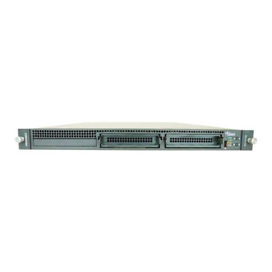
The PRIMERGY RX100 S3 server is an Intel-based server for small and medium-sized networks. The compact server casing (only one height unit) as well as its scalability and security features make the PRIMERGY RX100 S3 the perfect choice for operational areas data centers, Internet- and application- hosting. - Page 6 Overview of the documentation Introduction Information/procedure Manual Detailed safety notes Safety Features and technical data of the server Operating Manual Installation and operation, among other things: – External ports – Operation – Configuration of the server – Installation of the rack mounting kit Troubleshooting Installation/removal of all hot-plug components: –...
-
Page 7: Notational Conventions
Introduction Notational conventions Information/procedure Manual Replacement routines: Service Supplement – Replacing the LED board – Replacing the power supply unit – Replacing the system fans – Replacing the SATA backplane – Replacing the riser card – Replacing the processor – Replacing the system board Board layout BIOS setup BIOS Setup... -
Page 9: Procedure
Procedure CAUTION! The actions described in these instructions should only be performed by service personnel. Ê First of all please familiarize yourself with the safety instructions in the section chapter “Safety notes” on page 11 et seqq. . Ê Ensure that all required manuals (see Service DVD) are available, printing out the PDF files if necessary. -
Page 11: Safety Notes
Safety notes The following safety notes are also provided in the “Safety” manual. This device complies with the relevant safety regulations for data processing equipment. CAUTION! The actions described in these instructions should only be performed by service personnel. Before operating the device CAUTION! During installation and before operating the device, observe the instructions on environmental conditions for your device. - Page 12 Safety notes CAUTION! This device has a specially approved power cable and must only be connected to a grounded insulated socket. Ensure that the power socket on the device or the grounded wall outlet is freely accessible. The ON/OFF button does not disconnect the device from the mains voltage.
- Page 13 Safety notes CAUTION! Only install system expansions that satisfy the requirements and rules governing safety and electromagnetic compatibility and relating to telecommunications terminal equipment. If you install other expan- sions, you may damage the system or violate the safety regulations and regulations governing RFI suppression.
- Page 14 Safety notes CAUTION! All batteries containing pollutants are marked with a symbol (a crossed-out garbage can). In addition, the marking is provided with the chemical symbol of the heavy metal decisive for the classification as a pollutant: Cd Cadmium Hg Mercury Pb Lead Notes on handling CDs and CD-/DVD-ROM drives CAUTION!
- Page 15 Safety notes Note about the laser The CD-/DVD-ROM drive is classified for laser class 1according to IEC 60825-1. CAUTION! The CD-/DVD-ROM drive contains a laser diode (LED). Sometimes the LED produces a stronger laser beam than laser class 1. Direct view into this laser beam is dangerous.
- Page 16 Safety notes Use a grounding cable designed for this purpose to connect yourself to the system unit as you install components. Place all components on a static-safe base. You will find a detailed description for handling ESD components in the relevant European or international standards (DIN EN 61340-5-1, ANSI/ESD S20.20).
-
Page 17: Replacement Routines
Replacement routines CAUTION! Observe the safety instructions in the chapter “Safety notes” on page 11 et seqq. . Preparation 4.1.1 Opening the server Ê Terminate all applications and shut down the server correctly. Ê If your operating system has not switched off the server, press the on/off button. -
Page 18: Replacing The Led Board
Replacement routines Replacing the LED board The PRIMERGY RX100 S3 server’s chassis ID is stored on both the LED board and the system board. If in the event of failure, the LED board or the system board which has to be replaced must have the chassis ID rewritten. -
Page 19: Replacing The Power Supply Unit
ChassisID prom with the help of the "ChassisIDProm Tool" to enable ServerView and ServerStart to identify the system. You will find the tool on the ServerSupport CD and/or it can be downloaded from the Fujitsu Siemens Computers Service and Support page (URL: http://extranet.fujitsu-siemens.com/service/information/intelservers/tools). - Page 20 Replacing the power supply unit Replacement routines Figure 4: Making the pin free Ê Push the power supply unit in direction of the hard disks until the pin becomes free (see circle). Ê Push the new power supply unit into the bay until the pin is fully inserted. Make sure that the cables are not damaged.
-
Page 21: Replacing The System Fans
Replacement routines Replacing the system fans Replacing the system fans You will find two spare part numbers for system fans: – the two outside system fans are single fans – the three system fans in the middle; each consists of a dummy fan and a fan which are fastened with nylon rivets CAUTION! The system fans are non-redundant, you have to replace the defective... -
Page 22: Replacing The Sata Backplane
Replacing the SATA backplane Replacement routines Replacing the SATA backplane You will find the SATA backplane only in the hot-plug variant. Ê Open the server as described in the section “Preparation” on page 17. Ê Remove all the hot-plug hard disk drives (for a description see the Operating Manual). -
Page 23: Replacing The Riser Card
Replacement routines Replacing the riser card Figure 7: Positioning the SATA backplane Ê Position the SATA backplane on the hooks (see circles). Make sure that the SATA backplane fits in the guidances (see arrows). Ê Fasten the SATA backplane by pushing the green levels in the former position. - Page 24 Replacing the riser card Replacement routines Figure 8: Removing the riser card holder Ê Loosen the two knurled screws (see circles). Ê Remove the riser card holder by pulling upward from the system board. Ê If controllers have been installed in the PCI slots of the riser card, remove them (for a detailed description see the Options Guide).
-
Page 25: Replacing The Processor
Replacement routines Replacing the processor Replacing the processor CAUTION! Processors are modules which can react extremely sensitive to electro- static discharges and therefore must always be handled with care. After a processor has been removed from its protective sleeve or from its socket, place it with its smooth side down on a non-conducting, antistatic surface. - Page 26 Replacing the processor Replacement routines Figure 10: Removing an old processor Ê Press down the lever (1) and unhook it. Ê Fold up the frame. Ê Lift the installed processor carefully out of the socket (2). Figure 11: Inserting a new processor Ê...
- Page 27 Replacement routines Replacing the processor Figure 12: Fixing the processor Ê Fold down the frame (1). CAUTION! The processor holder must fall down by itself. Do not close with force, because soldering pads may be damaged. Ê Press the lever slowly downward (2) until it is hooked in again (3). Ê...
- Page 28 Replacing the processor Replacement routines Figure 13: Installing the heat sink Ê Position the heat sink carefully on the processor. Ê Position the screws in the holes carefully, making sure they are upright. Ê Tighten the four screws crosswise (see arrows). Ê...
-
Page 29: Replacing The System Board
Replacing the system board Replacing the system board The PRIMERGY RX100 S3 server’s chassis ID is stored on both the LED board and the system board. If in the event of failure, the LED board or the system board which has to be replaced must have the chassis ID rewritten. - Page 30 Replacing the system board Replacement routines Figure 14: Removing the screws Ê Remove the nine screws from the system board. Ê Carefully lift the system board out of the chassis at a slight angle. Ê Check the settings on the new system board (for a description see the Technical Manual of the system board).
- Page 31 ChassisID prom with the help of the "ChassisIDProm Tool" to enable ServerView and ServerStart to identify the system. You will find the tool on the ServerSupport CD and/or it can be downloaded from the Fujitsu Siemens Computers Service and Support page (URL: http://extranet.fujitsu-siemens.com/service/information/intelservers/tools).
-
Page 33: Appendix
Appendix Board layout The board layout of the system board is described in the Technical Manual of the system board D2004. 5.1.1 LED board Part number: S26361-D1753-A10 Connector cable Service Supplement RX100 S3... -
Page 34: Sata Backplane (Only For Hot-Plug Variant)
Board layout Appendix 5.1.2 SATA backplane (only for hot-plug variant) Part number: S26361-D2266-A10 Connector SATA cable for hard disk 2 Connector SEP IPMB cable Connector SATA LED cable Connector SATA cable for hard disk 1 Connector power cable Service Supplement RX100 S3... -
Page 35: Riser Card 1
Appendix Board layout 5.1.3 Riser card 1 Part number: S26361-E395-A10 PCI-X (64 Bit / 100 MHz) slot PCI-X (64 Bit / 100 MHz) slot Service Supplement RX100 S3... -
Page 36: Riser Card 2
Board layout Appendix 5.1.4 Riser card 2 Part number: S26361-E396-A10 PCI Express x4 slot PCI-X (64 Bit / 100 MHz) slot Service Supplement RX100 S3... -
Page 37: Cabling
Appendix Cabling Cabling LED board A3C40052663 Power supply unit Hard disk 1 CN11 CN12 A3C40066751 Hard disk 2 CN19 CN14 A3C40066751 A3C40068694 Fan 5 Fan 4 CD-ROM / DVD drive Fan 3 LAN 2 Fan 2 LAN 1 3 x A3C40069325 CN17 A3C40068703 DIMM1A... - Page 38 Cabling Appendix LED board A3C40052663 Power supply unit Non-hot-plug hard disk 1 CN11 CN12 A3C40066751 Non-hot-plug CN19 CN14 hard disk 2 A3C40066751 A3C40068694 Fan 5 Fan 4 CD-ROM / DVD drive Fan 3 LAN 2 Fan 2 LAN 1 3 x A3C40069325 CN17 DIMM1A CN16...
-
Page 39: Index
Index ESD (devices sensitive to electrostatic discharge) 15 LED board 18, 33 light-emitting diode (LED) 15 lithium battery 13 meaning of the symbols 7 notational conventions 7 note about the laser 15 power supply unit 19 processor 25 riser card 23 riser card 1 35 riser card 2 36 SATA backplane 22, 34... - Page 41 Comments Fujitsu Siemens Computers GmbH User Documentation 81730 München Suggestions Germany Corrections Fax: (++49) 700 / 372 00000 email: manuals@fujitsu-siemens.com http://manuals.fujitsu-siemens.com Submitted by Comments on PRIMERGY RX100 S3 Server System...
- Page 43 Comments Fujitsu Siemens Computers GmbH User Documentation 81730 München Suggestions Germany Corrections Fax: (++49) 700 / 372 00000 email: manuals@fujitsu-siemens.com http://manuals.fujitsu-siemens.com Submitted by Comments on PRIMERGY RX100 S3 Server System...
- Page 45 Information on this document On April 1, 2009, Fujitsu became the sole owner of Fujitsu Siemens Compu- ters. This new subsidiary of Fujitsu has been renamed Fujitsu Technology So- lutions. This document from the document archive refers to a product version which was released a considerable time ago or which is no longer marketed.