
Related Manuals for Siemens TUTORbit POL687


Summary of Contents for Siemens TUTORbit POL687
- Page 1 INSTALLATION, USE AND MAINTENANCE MANUAL TUTORbit CASCADE SEQUENCE, HEATING AND COOLING SYSTEM CONTROLLER 62403737 - R02 21-12-2020_UK...
-
Page 2: Table Of Contents
INDEX 1 - GENERAL SAFETY WARNINGS ........................4 1.1 - National installation laws ............................4 2 - GENERAL INFORMATION ..........................5 2.1 - Introduction ................................5 2.2 - Meaning of the symbols used ..........................5 2.3 - Disposal ................................... 5 3 - DIMENSIONS ..............................6 3.1 - Dimensions ................................ -
Page 3: Index
INDEX 5 - ALARMS AND DIAGNOSTICS........................63 5.1 - Alarms ..................................63 5.1.1 - BSP and BUS lights on Tutorbit ........................ 65 5.1.2 - Expansion BSP and BUS lights ........................ 65 5.1.3 - Anti-legionella alarm ..........................66 5.2 - Degraded operation ............................... 66 5.3 - Saving and/or restoring the configuration ...................... -
Page 4: General Safety Warnings
1 - GENERAL SAFETY WARNINGS Installation, changes In case of failure In case of failure and/or appliance malfunction, deactivate it Installation, calibration or modification of the appliance and do not attempt any repairs. Always contact a professionally must be carried out by professionally qualified personnel, qualified technician. -
Page 5: General Information
2 - GENERAL INFORMATION 2.1 - Introduction This manual is for the TutorBit system which may consists of the following products Code Description 62612791 TutorBit_ System controller consisting System controller able to control: of a POL687 model controller and a - Up to 4 heat generators POL895 remote control - Two heating circuits... -
Page 6: Dimensions
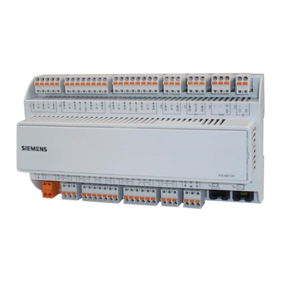
3 - DIMENSIONS 3.1 - Dimensions POL687 controller POL895 Remote control The remote control must be connected to the T_HI connector on TutorBit. The cable can be extended up to 30m. ATTENTION !!! Since the control cables are subjected to very low safety voltage (24Vdc), they must flow in conduits other than 230Vac power supplies. - Page 7 3 - DIMENSIONS Figure 3-2 - Dimensions of the expansion POL945 Figure 3-3 - Dimensions of the expansion POL955 80.5 88.4 26.5 28.2 28.2 Figure 3-4 - Dimensions of QMX3 Room sensor COSMOGAS TUTORBIT...
-
Page 8: Installation
4 - INSTALLATION 4.1 - TutorBit electrical connections - a DHW enable / disable input; - Modbus communication to the MYDENS T or AGUADENS The TutorBit controller is a system manager able to control: T models heat generators; - until 4 heater modules; - Ethernet communication to PC (WEB Server connection) - two heating zones;... - Page 9 4 - INSTALLATION Legend Corresponding Characteristics of the cables to be used and Figure Input/output description terminals on maximum electrical absorption controller POL687 “Water Heater Temperature” sensor B1; M (1) Ø 1,5 mm / 20 m Max o 100 m shielded cable; (47) (NTC 10kohm B3435) Zone 1 sensor B2;...
-
Page 10: Electrical Connections Of Pol 945 Expansion
4 - INSTALLATION 4.2 - Electrical connections of POL 945 expansion The POL 945 expansion can be used for different purposes, depending on the logical address that is set (see Section 4.4). When the logical address “1” is set, the POL 945 expansion can control: a.- An heating zone;... -
Page 11: Electrical Connections Of Pol955 Expansion
4.3 - Electrical connections of POL955 expansion The POL955 expansion is used to control only a heat pump. For this purpose, various configurable inputs and outputs have been provided (see detail in Figure 4-4), in order to adapt the controller to most of the heat pumps on the market. To properly communicate the expansion with the regulator, it is always necessary to set logical address “5”, by positioning the microswitches (Section 4.4). -
Page 12: Expansions And Logical Addresses
4 - INSTALLATION 4.4 - Expansions and logical addresses Up to 3 POL945 expansions and one POL955 expansion can be connected to the TutorBit regulator. In order to identify each POL 687 POL 945 (Zone 3) expansion, by the operating program, it is necessary to give it Slave Addresses a logical recognition address, by positioning the microswitches in each expansion (see Figure 4-5). -
Page 13: Qmx3 Room Sensor
4 - INSTALLATION 4.5 - QMX3 Room sensor The QMX3 room sensor, if combined with a mixed circuit, is able to regulate the temperature of the heating / cooling zone in a modulating way with respect to the temperature of the room where the sensor is located. -
Page 14: Installation
4 - INSTALLATION “Distributed power” configuration ATTENTION!!! If the DHW mode is “Thermostat”, the Anti- Figure 4-10 shows the application diagram of a system where legionella service cannot be completed. The installer must take all necessary precautions to prevent the legionella all the heat modules are controlled in parallel to produce heating, whereas a single module is intended to produce bacteria from growing in order to avoid seriously harming... -
Page 15: Modbus Communication With Boilers/Water Heaters
4 - INSTALLATION 4.9 - Heating / Cooling management - Heat pump Enable or not a heat pump for heating / cooling and / or DHW. To enable cooling, a heat pump must be installed as shown in Access the menu Configuration->Heat pump->HP mode the diagrams in Chapter 4.21. -
Page 16: Heating / Cooling Zones
4 - INSTALLATION 4.11 - Heating / Cooling zones Opening the room thermostat input, corresponding to that circuit, always causes a stop of the service. The heating zones can work independently to each other and The parameters for adjusting the outdoor reset can be found in various modes, which can be selected in Configuration- in Parameters->Modules->Heat. - Page 17 - FxSp-Comp.RT (Heating/Cooling at constant temperature Similarly, for cooling, the parameters for adjusting the outdoor with room sensor compensation). reset can be found in Parameters->Modules->Cool. Outdoor This mode is exactly the same as the FxSp-RT mode, the only Reset and are: difference being that if the RT is opened, the heating is not stopped but the supply temperature is reduced, corresponding - Set Minimum...
-
Page 18: Dhw Management
4 - INSTALLATION 4.12 - DHW management - “Distributed power” DHW The heating service for the hot water tank is carried out with The DHW temperature is set in Parameters->DHW->DHW the “Distributed power” mode: when DHW is requested, only setpoint. the module(s) in the Configuration->System->Module n = There are two DHW modes: DHW parameter convert(s) to load the DHW tank and when... - Page 19 4 - INSTALLATION Figure 4-10 - “Distributed power” DHW diagram Key to Figures 4-9 and 4-10 1 - Module 2 - Modbus communication connection (optional) 3 - 0-10V connection 4 - Heating zones (maximum of 3 zones) 8 - 230Vac - 24Vac transformer 9 - Thermoregulator’s outdoor temperature sensor (Outdoor Temp.) 10 - Thermoregulator 31 - Pump to load the hot water tank (Tank pump)
-
Page 20: Anti-Legionella
4 - INSTALLATION 4.12.1 - Anti-legionella 4.13 - Shuffle pump The anti-legionella function differs depending on whether the The shuffle pump is set in Configuration->System->Shuffle hot water tank is loaded only by the modules or also by the pump type and has the following selections: solar zone. -
Page 21: Rotation Of The Modules
4 - INSTALLATION 4.17 - Antifrost Solar Antifrost The solar panel is protected by an antifrost cycle. When the If you want to stop the system for a long period of time (for antifrost cycle is working, “ANF” is displayed on the main page. example, if you go on holiday), you can set the system in The antifrost cycle can be disabled by setting Configuration- antifrost. -
Page 22: Connection Of Tutorbit To Heat Pump (Hp)
4 - INSTALLATION 4.18 – Connection of TutorBit 4.18.1 - System operation with heat pump (HP) in heating to Heat Pump (HP) HP has a good operating efficiency only for certain outdoor To connect to HP it is necessary to connect a POL 955 temperatures. -
Page 23: System Operation With Heat Pump (Hp) In Cooling
4 - INSTALLATION 4.18.2 - System operation with heat pump (HP) in cooling The cooling function is activated only if the outside temperature is higher than Parameters -> Modules -> Autumn Temp. When the heat pump is running, it meets the required sensor temperature Water Heater T. -
Page 24: Room Sensor Qmx3 Model
4 - INSTALLATION 4.19 – Room sensor QMX3 model 5.- Once the ID is set, go to Configuration -> Zones -> Associate SN Circuit N = Yes for how many zones are The QMX3 room control is connected to TutorBit via the KNX there;... -
Page 25: Connection Test
4 - INSTALLATION The device restarts after 10 seconds and will show: Then press the 3 key. In the case of a good connection, the display will show “TEST DONE”: Attention! This operation restores all factory settings and is irreversible. To reconnect QMX3 it will be necessary to follow the procedure again in Section 4.19.1. -
Page 26: Connecting Tutorbit To A Personal Computer
4 - INSTALLATION 4.20 - Connecting TutorBit to a Personal computer TutorBit can be connected to a PC to display an interactive operating diagram and to easily browse through the menu (Section 6.13). To this end, proceed as follows: 1.- Connect an Ethernet cable to the “T-IP” port on the TutorBit (See Figure 4-2);... - Page 27 4 - INSTALLATION 1,5V 1,5V 1,5V 1,5V 1,2 bar 1,2 bar 1,2 bar 1,2 bar 19°C MODBUS 1 MODBUS 2 MODBUS 3 MODBUS 4 60°C 60°C 60°C 60°C 60°C 59°C State HP Signal HEAT 0-10V signal from the TutorBit Module water pressure Burner error Burner power level MODBUS address...
- Page 28 4 - INSTALLATION 45°C 45°C 45°C 45°C 45°C 45°C 45°C 45°C 45°C 45°C 70°C 7°C ∆t 55°C 60°C 63°C 42°C 41°C Measured cascade temperature sensor Hot water tank sensor measured temperature DHW enable/disable input (enabled = Green / disabled = 3 way valve opening level Red) Heating zone supply setpoint...
-
Page 29: Installation Diagrams Of Cascade Sequencer With Boiler
4 - INSTALLATION 4.21 - Installation diagrams of cascade sequencer with boiler Tutorbit can be used to create an innumerable type of systems. The most common types with the settings and the relative wiring diagram are shown below. The Legend, shown below, applies to all these diagrams. -
Page 30: Modules Mydens T With 2 Heating Zones, Dhw And Dhw Return
4 - INSTALLATION COSMOGAS TUTORBIT... - Page 31 4 - INSTALLATION COSMOGAS TUTORBIT...
-
Page 32: Heating Zone, Dhw, Dhw Ruturn, Solar And Anti-Legionella Shuffle Pump
4 - INSTALLATION COSMOGAS TUTORBIT... - Page 33 4 - INSTALLATION COSMOGAS TUTORBIT...
-
Page 34: Heating Zones, Dhw, Dhw Return, Solar And Anti-Legionella Shuffle Pump
4 - INSTALLATION COSMOGAS TUTORBIT... - Page 35 4 - INSTALLATION COSMOGAS TUTORBIT...
-
Page 36: Heating Zones, Dhw, Dhw Return, Solar And Anti-Legionella Shuffle Pump
4 - INSTALLATION COSMOGAS TUTORBIT... - Page 37 4 - INSTALLATION COSMOGAS TUTORBIT...
-
Page 38: Heating Zones, Dhw, Dhw Return, Solar, Anti-Legionella Shuffle Pump, Heat Pump For Heating And Dhw Integration
4 - INSTALLATION COSMOGAS TUTORBIT... - Page 39 4 - INSTALLATION COSMOGAS TUTORBIT...
-
Page 40: Heating Zones, Dhw, Dhw Return, Solar, Anti-Legionella Shuffle Pump And Only One Module Switch To Dhw
4 - INSTALLATION COSMOGAS TUTORBIT... - Page 41 4 - INSTALLATION COSMOGAS TUTORBIT...
-
Page 42: Heating Zones, Heat Pump With Heating And Cooling Integration
4 - INSTALLATION COSMOGAS TUTORBIT... - Page 43 4 - INSTALLATION COSMOGAS TUTORBIT...
-
Page 44: Heating Zones, Dhw, Dhw Return, Solar, 2 Tanks (One Solar And One Of The Module)
4 - INSTALLATION COSMOGAS TUTORBIT... - Page 45 4 - INSTALLATION COSMOGAS TUTORBIT...
-
Page 46: Heating Zones, Dhw, Dhw Return, 2 Tanks
4 - INSTALLATION COSMOGAS TUTORBIT... - Page 47 4 - INSTALLATION COSMOGAS TUTORBIT...
-
Page 48: Heating Zones, Dhw Produced By Aguadens-T, Dhw Return, Solar, Antilegionella Shuffle Pump And 3 Modules Dedicated To Heating
4 - INSTALLATION COSMOGAS TUTORBIT... - Page 49 4 - INSTALLATION COSMOGAS TUTORBIT...
-
Page 50: Heating Zones, Dhw, Dhw Return, Solar, 2 Tanks (1 For Solar And 1 For Boiler) And Solar Transfer Fun- Ction
4 - INSTALLATION COSMOGAS TUTORBIT... - Page 51 4 - INSTALLATION COSMOGAS TUTORBIT...
-
Page 52: Heating Circuit With Heat Pump Integration, Dhw, Dhw From Pdc, Dhw Return, Solar, 2 Tanks ( 1 Solar And 1 Boiler) And Solar Transfer Function
4 - INSTALLATION COSMOGAS TUTORBIT... - Page 53 4 - INSTALLATION COSMOGAS TUTORBIT...
- Page 54 4 - INSTALLATION COSMOGAS TUTORBIT...
-
Page 55: Installation Diagrams Of Cascade Sequencer With Water Heater
4 - INSTALLATION 4.22 - Installation diagrams of cascade sequencer with water heater Tutorbit can be used to create an innumerable type of systems. The most common types with the settings and the relative wiring diagram are shown below. The Legend, shown below, applies to all these diagrams. -
Page 56: Water Heater With Tank Without Coil, Dhw And A Dhw Return Zone
4 - INSTALLATION COSMOGAS TUTORBIT... - Page 57 4 - INSTALLATION COSMOGAS TUTORBIT...
-
Page 58: Water Heater With Tank Without Coil, Dhw, Dhw Return And Solar
4 - INSTALLATION COSMOGAS TUTORBIT... - Page 59 4 - INSTALLATION COSMOGAS TUTORBIT...
- Page 60 4 - INSTALLATION COSMOGAS TUTORBIT...
- Page 61 4 - INSTALLATION COSMOGAS TUTORBIT...
-
Page 62: Communication Protocols Towards Home Automation Systems
4 - INSTALLATION 4.23 - Communication protocols towards home automation systems TutorBit can be connected to a supervisor via the protocols: - MODBUS TCP / IP - MODBUS RTU - KNX - BACNET The MODBUS TCP / IP connection is made through the same Ethernet port. -
Page 63: Alarms And Diagnostics
5 - ALARMS AND DIAGNOSTICS 5.1 - Alarms A bell is displayed on the screen when there is an alarm (see Figure 6-2, detail 3). Proceed as follows to query an alarm: 1.- Press the “Bell” key on the main menu; 2.- Select the Alarms list menu;... - Page 64 5 - ALARMS AND DIAGNOSTICS A015 Anti-stagnation : Alarm; Solar circuit Anti-stagnation alarm; a.- Check actual solar circuit a.- Wait for the temperature temperature; to drop; b.- Check the state of the solar probe; b.- Replace the solar probe; A016- Sp 0-10V external : Low limit alarm; Low communication signal alarm (<...
-
Page 65: Bsp And Bus Lights On Tutorbit
5 - ALARMS AND DIAGNOSTICS A040 Gener. 3 Burner 3 Module 3 error alarm; Check the type of error on the generator Restore by following the 3 display; instructions provided with the generator; A041 Gener. 3 Burner 4 Module 3 error alarm; Check the type of error on the generator Restore by following the 3 display;... -
Page 66: Anti-Legionella Alarm
5 - ALARMS AND DIAGNOSTICS 5.1.3 - Anti-legionella alarm 5.2 - Degraded operation The anti-legionella alarm is the only alarm “with For the purpose of diagnostics or to solve an emergency acknowledgement”. If the system is not able to complete the situation, you can use the Diagnostics menu at any time to anti-legionella cycle, the anti-legionella alarm is displayed. -
Page 67: Use
6 - USE 6.1 - Main page When you switch on TutorBit, you automatically access the home screen that shows the status of the system. Figure 6-1 shows the main screen in its maximum configuration, with the explanation of each row. Information on the home screen Description of the contents Cosmogas Srl = company name;... -
Page 68: General Information
6 - USE Figure 6-2 - Control panel Figure 6-2 key Display; Selected parameter (highlighted) / Number of parameters displayed; Triggered alarm symbol; INFO key (N/A); “Bell” key to display the alarms menu; Rotate to browse through the menu parameters; enter the selected parameter;... -
Page 69: Access Profile
6 - USE 6.3 - Access profile 6.5 - DHW adjustment The menus on TutorBit can be displayed according to the To set the DHW, open Parameters->DHW->DHW setpoint access profile: and set the required temperature - User Profile - Installer Profile To operate the DHW according to the time programme, set - Factory Profile Parameters->DHW->DHW Action = Automatic then set the... -
Page 70: Cooling Adjustmen
6 - USE 6.7 - Cooling adjustmen 6.10 - Heating circuits time setting To deactivate or set the cooling to zones “n” (intended as “n” of any of the 5 zones) automatically (operation according to the For the heating circuits time setting, open the Parameters- time bands) or manually (operation at constant temperature) >Zones->Programme->... -
Page 71: Qmx3 Room Sensor Using
6 - USE 6.12 - QMX3 room sensor using - Key 1: Switches the display between the outdoor and room temperature; - Key 2 and 6: Room temperature setpoint adjustment; - Keys 3, 4, 5 and 8: No function; - Key 7: Selecting the room operating mode: - AUTO = Heating / Cooling according to the time slots inserted in the corresponding zone in TutorBit;... -
Page 72: Setting The Desired Room Temperatures
6 - USE 6.12.1.- Setting the desired room 6.12.2.- Time program of the heating / temperatures cooling zones served by the QMX3 room sensor To change the temperature values corresponding to Comfort / Precomfort / Reduced / Antifreeze, proceed as follows: When there is a room sensor connected to a heating / cooling zone, the time program of this circuit takes place directly on TutorBit, at the relative menu Parameters ->... -
Page 73: Tutorbit Menus
6 - USE 6.13 - Tutorbit menus Tutorbit has many parameters for setting and customising the system. The following pages show the menu with the browsing levels (shown in the “Parameters” field), the description, the access profiles, the adjustment field, the default values (from when it leaves the factory) and an empty field for the installer to note down any customisation made to the system. - Page 74 6 - USE COSMOGAS TUTORBIT...
- Page 75 6 - USE COSMOGAS TUTORBIT...
- Page 76 6 - USE COSMOGAS TUTORBIT...
- Page 77 6 - USE COSMOGAS TUTORBIT...
- Page 78 6 - USE COSMOGAS TUTORBIT...
- Page 79 6 - USE COSMOGAS TUTORBIT...
- Page 80 6 - USE COSMOGAS TUTORBIT...
- Page 81 6 - USE COSMOGAS TUTORBIT...
- Page 82 6 - USE COSMOGAS TUTORBIT...
- Page 83 6 - USE COSMOGAS TUTORBIT...
- Page 84 6 - USE COSMOGAS TUTORBIT...
- Page 85 6 - USE COSMOGAS TUTORBIT...
- Page 86 6 - USE COSMOGAS TUTORBIT...
- Page 87 6 - USE COSMOGAS TUTORBIT...
- Page 88 6 - USE COSMOGAS TUTORBIT...
- Page 89 6 - USE COSMOGAS TUTORBIT...
- Page 90 6 - USE COSMOGAS TUTORBIT...
- Page 91 6 - USE COSMOGAS TUTORBIT...
- Page 92 6 - USE COSMOGAS TUTORBIT...
- Page 93 6 - USE COSMOGAS TUTORBIT...
- Page 94 6 - USE COSMOGAS TUTORBIT...
- Page 95 6 - USE COSMOGAS TUTORBIT...
- Page 96 COSMOGAS s.r.l. Via L. da Vinci 16 - 47014 MELDOLA (FC) ITALY info@cosmogas.com www.cosmogas.com...