Table of Contents
Troubleshooting

Related Manuals for Panasonic ST4


Summary of Contents for Panasonic ST4
- Page 1 safety BEAM SENSOR instruction Manual SEN TRONIC Rugghölzli 2 Tel. +41 (0)56 222 38 18 mailbox@sentronic.com CH - 5453 Busslingen Fax +41 (0)56 222 10 12 www.sentronic.com Produkte, Support und Service...
- Page 2 The printed English and Japanese versions of this instruction manual are the original versions. The English, French, German, Italian and Spanish versions published in the Internet are copies of the original documentation and were produced by Panasonic Electric Works Europe Liability and Copyright for the Hardware This manual and everything described in it are copyrighted.
- Page 3 Important Symbols One or more of the following symbols may be used in this documentation: DANGER! The warning triangle indicates especially important safety instructions. If they are not adhered to, the results could be fatal or critical injury. CAUTION Indicates that you should proceed with caution. Failure to do so may result in injury or significant damage to instruments or their contents, e.g.
- Page 4 KEY POINTS Summarizes key points in a concise manner. SHORTCUTS Provides helpful keyboard shortcuts. EXPLANATION Provides a brief explanation of a function, e.g. why or when you should use it. next page Indicates that the text will be continued on the next page. SEN TRONIC Rugghölzli 2 Tel.
-
Page 5: Table Of Contents
2. Before Using this Device ............7 Features..................... 8 Part Description ..................9 2.2.1 Elements of the Controller ST4-C11 ............10 2.2.2 Elements of the Multifunctional Controller ST4-C12EX ......11 2.2.3 Elements of the Sensor ST4-A..............14 Protection Area ..................15 2.3.1 Sensing Range..................15 2.3.2... - Page 6 Interference Prevention Function When Using Two or More Controllers 54 Auxiliary Output ..................56 3.5.1 Auxiliary Output Operation of Controller ST4-C11........56 3.5.2 Auxiliary Output Operation of Controller ST4-C12EX ......56 3.5.3 Emission Amount Adjustment Function ...........57 Muting Function (Only for ST4-C12EX)............59 3.6.1 What Is a Muting Sensor ................60...
- Page 7 3.8.3 Control Condition of Muting Pattern No. 3 ..........70 Sensor Diagnosis Function (Only ST4-C12EX)........71 3.10 Muting Lamp Diagnosis Function (Only ST4-C12EX) ......74 4. Maintenance................75 Daily Inspection ..................76 Periodic Inspection Checklist (Every Six Months) ........77 Inspection After Maintenance ..............
- Page 8 Multifunctional Controller ST4-C12EX............97 Single-beam Sensor ST4-A□ ..............98 Branch Cable ST4-CCJ05-WY..............99 Foot Angled Mounting Bracket MS-CX-1 ..........100 Back Angled Mounting Bracket MS-ST4-3..........101 Foot Biangled Protective Mounting Bracket MS-ST4-6......102 8. Glossary of Terms.............. 103 9. Index..................105 viii SEN TRONIC Rugghölzli 2 Tel.
-
Page 9: Introduction
Chapter 1 Introduction SEN TRONIC Rugghölzli 2 Tel. +41 (0)56 222 38 18 mailbox@sentronic.com CH - 5453 Busslingen Fax +41 (0)56 222 10 12 www.sentronic.com Produkte, Support und Service... -
Page 10: Target Group
Panasonic ST4 Instruction Manual 1.1 Target Group Thank you for purchasing the PanasonicSafety Beam Sensor ST4 series (hereafter called 'this device'). Please read this instruction manual carefully and thoroughly for the correct and optimum use of this product. Kindly keep this manual in a convenient place for quick reference. -
Page 11: Safety Instructions
Panasonic ST4 Instruction Manual 1.2 Safety Instructions 1.2 Safety Instructions DANGER! Please adhere to the following safety instructions when you install and operate this device. Failure to do so can result in fatal or critical injury during unprotected use of hazardous machinery. - Page 12 Introduction Panasonic ST4 Instruction Manual Areas exposed to intense interference light such as direct sunlight Areas with high humidity where condensation is likely to occur Areas exposed to corrosive or explosive gases Areas exposed to vibration or shock at levels higher than those specified...
- Page 13 Do not run the sensor cable together with high-voltage lines or power lines or put them together in the same raceway. • In case you need to extend the cable of the ST4-A□, you can use the dedicated extension cable. The cable can be extended up to 50m (emitter and receiver, respectively).
-
Page 14: Applicable Standards/Regulations
Introduction Panasonic ST4 Instruction Manual 1.3 Applicable Standards/Regulations This device complies with the following standards and regulations. • EU Machinery Directive 98/37/EC, EMC Directive 2004/108/EC • EN 61496-1 (Type 4), EN 55011, EN 50178, EN ISO 13849 (Category 4, PLe), EN 61508-1 to 7 (SIL3) •... -
Page 15: Before Using This Device
Chapter 2 Before Using this Device SEN TRONIC Rugghölzli 2 Tel. +41 (0)56 222 38 18 mailbox@sentronic.com CH - 5453 Busslingen Fax +41 (0)56 222 10 12 www.sentronic.com Produkte, Support und Service... -
Page 16: Features
The type ST4-A□V comes with an emission amount adjuster to reduce the emission amount. • Up to six units of the ST4-A□ can be connected per controller. The controller has an automatic interference prevention function. • Wiring can be easily done by using the extension cable ST4-CCJ□ (optional) and the branch cable ST4-CCJ05-WY (optional), since the cables are connector types •... -
Page 17: Part Description
Panasonic ST4 Instruction Manual 2.2 Part Description 2.2 Part Description The ST4 system can be built up from the following parts. Which controller type you choose depends on your requirements and applications. Part name Part Controller ST4-C11 Multifunctional Controller ST4-C12EX... -
Page 18: Elements Of The Controller St4-C11
Panasonic ST4 Instruction Manual Part name Part (optional) Branch cable ST4-CCJ-WY (optional) Slit mask (optional) 2.2.1 Elements of the Controller ST4-C11 4 5 6 7 8 Identifier Function Emitter connector Connects the emitter of the ST4-A□. Receiver connector Connects the receiver of the ST4-A□. -
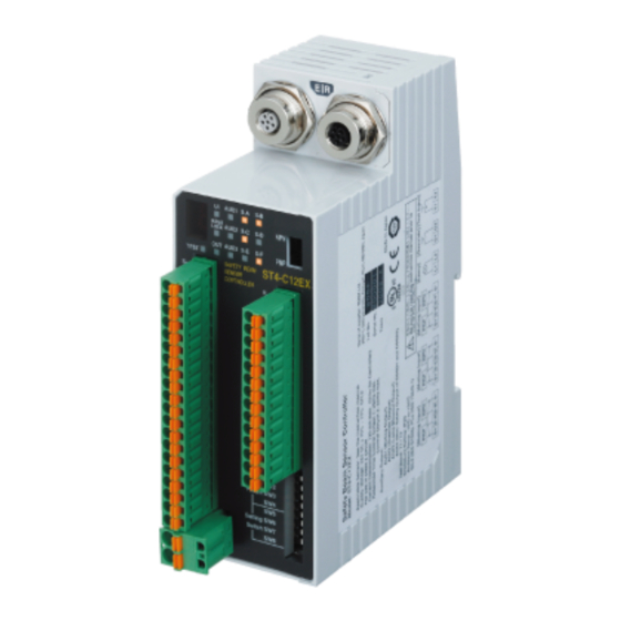
Page 19: Elements Of The Multifunctional Controller St4-C12Ex
X3 are connected: auto reset) Emission halt input terminals (Open: emission halt, Short-circuit: emission) OSSD 1 Control output (OSSD 1/2) OSSD 2 2.2.2 Elements of the Multifunctional Controller ST4-C12EX Identifier Function Emitter connector Connects the emitter of the ST4-A□. Receiver connector Connects the receiver of the ST4-A□. - Page 20 Sets the ST4-A□ into the muting state. 1 to 4 Sets effective time for muting/override (see page 59). Checks the states "beam received" and "beam interrupted" of the connected ST4-A□, or a sensor error (see "Sensor Diagnosis Function (Only ST4-C12EX)" on page 71). Unused Deactivates the muting lamp diagnosis function (see page 74).
- Page 21 Panasonic ST4 Instruction Manual 2.2 Part Description Terminal block Terminal Name Description Muting input power supply (24V) Muting input S-A (for PNP type) Muting input S-B (for NPN type) Muting input power supply (0V) Muting input power supply (24V) Muting input S-C (for PNP type)
-
Page 22: Elements Of The Sensor St4-A
Turns off when incident beam intensity is 150% or less. (Note 2) indicator (Green) NOTE 1. Only available with the ST4-A□V type. 2. The incident beam intensity that turns the control output (OSSD 1/2) to ON is regarded as 100%. SEN TRONIC Rugghölzli 2... -
Page 23: Protection Area
This example shows what a protective structure could be, where the dangerous part of a machine should be situated and how the emitter and receiver can be arranged. EXAMPLE Installing four units of the ST4-A□ Protective structure Receiver of the ST4-A□... -
Page 24: Safety Distance
The safety distance is the minimum distance that must be maintained between the ST4-A□ and the dangerous parts of the machine so that the machine can be stopped before a human body or an object can reach the dangerous parts. -
Page 25: Calculation Example For Europe
Panasonic ST4 Instruction Manual 2.3 Protection Area 2.3.2.1 Calculation Example for Europe The minimum safety distance S is calculated in accordance with EN 999 and ISO 13855 with the following equation: S = K x T + C Safety distance (mm) Minimum distance required between the sensing area surface and the dangerous parts of the machine. -
Page 26: Calculation Example For The Us
Before Using this Device Panasonic ST4 Instruction Manual = K x T + C = 1600 × (T ) + 850 = 1600 × (0.1s + 0.025s) + 850 = 1600 × 0.1s + 1600 × 0.025 + 850 = 160 + 40 + 850 = 1050 Hence, as per the calculations S is 1050mm. - Page 27 Panasonic ST4 Instruction Manual 2.3 Protection Area Example calculation of the safety distance for a "REACH OVER" application Topmost beam axis 35.434 inch (≈ 900mm) or more 11.812 inch (≈ 300mm) or less Undermost beam axis The following default values of ANSI/RIA 15.06 are used for the example calculation: Detectable minimum sensing Min.
-
Page 28: Influence Of Reflective Surfaces
Before Using this Device Panasonic ST4 Instruction Manual Detectable minimum sensing object Min. 2.52inch (≈ 64mm) and max. 23.623inch (≈ 600mm) Undermost beam axis 11.812inch (≈ 300mm) or less Topmost beam axis 47.245inch (≈ 1200mm) or more 0.5s 35.434inch (≈ 900mm) = K ×... -
Page 29: Placement Of Emitter And Receiver
Panasonic ST4 Instruction Manual 2.3 Protection Area Install this device at a distance of at least A m (provided as follows) away from reflective surfaces such as metal walls, floors, ceilings, work pieces, covers, panels or glass surfaces. Side view... - Page 30 Before Using this Device Panasonic ST4 Instruction Manual DANGER! Refer to the examples of device placement as follows and understand them thoroughly before installation. Improper placement could cause device malfunction, which can result in serious injury or death. If this device is used in multiple sets, avoid mutual interference.
-
Page 31: Connecting Multiple Sensors Heads
2.3.5 Connecting Multiple Sensors Heads You can connect up to six units of the ST4-A□ per controller. The cable length between all emitters and the controller, as well as between all receivers and the controller, must not exceed 50m, respectively. - Page 32 ST4-CCJ□ (Optional) Procedure 1. Insert the male emitter connector of the ST4-A□ (color: gray) into the female emitter connector of the controller (color: gray). 2. Insert the male receiver connector of the ST4-A□ (color: black) into the female receiver connector of the controller (color: black).
-
Page 33: Address Allocations Of The Sensor St4-A
3. Make sure to use the optional exclusive cable (ST4-CCJ□, ST4-CCJ05-WY) for wiring, and match the connector colors (gray: emitter, black: receiver). 4. After installing the ST4-A□, check that the ST4-A□ detects a part of human body before it reaches to the dangerous part of the machine, by watching the beam interruption indicator (red). - Page 34 Before Using this Device Panasonic ST4 Instruction Manual Connection example 1: No branching between the ST4-A□ and the ST4-CCJ05-WY when six units are connected Emitter of ST4-A□ Receiver of ST4-A□ Address 6 Address 6 Address 5 Address 5 Address 4...
- Page 35 Addresses are automatically allocated in the order of the arrows shown in the preceding figure. • Addresses of the ST4-A□ are allocated in the order of the numbers that are marked on the main body of ST4-CCJ05-WY (optional). SEN TRONIC Rugghölzli 2...
- Page 36 Panasonic ST4 Instruction Manual • Connect the ST4-A□s to the connector numbers 2 and 3 of the branch cable ST4-CCJ05-WY (optional). If the ST4-A□s are not connected to the connectors 2 and 3, the device will not operate properly. For an unconnected condition, the fault indicator (yellow) of ST4-C11 blinks once.
-
Page 37: Mounting And Removing
Panasonic ST4 Instruction Manual 2.4 Mounting and Removing 2.4 Mounting and Removing 2.4.1 Mounting and Removing the Controller The controller can be mounted on a 35mm width DIN rail. Procedure 1. Push the DIN rail stopper. 2. Fit the tab on the opposite side of the DIN rail stopper onto the DIN rail. -
Page 38: Mounting The Sensor St4-A
Please purchase the optional sensor mounting bracket that fits with the mounting environment. DANGER! After installing the ST4-A□, check that the ST4-A□ detects a part of human body before it reaches to the dangerous part of the machine, by watching the beam interruption indicator (red). -
Page 39: Connecting Controller And Sensor St4-A
This may result in serious injury or death. The emitter of the ST4-A□ (connector color: gray) has to be connected with the emitter connector of the controller (connector color: gray). The receiver of the ST4-A□ (connector color: black) has to be connected with the receiver connector of the controller (connector color: black). -
Page 40: Series Connection Of The Sensor St4-A
2.4.4 Series Connection of the Sensor ST4-A□ You can connect up to six units of the ST4-A□ per controller in series. When connecting several sensors, the extension cable ST4-CCJ□ (optional) and the branch cable ST4-CCJ05-WY (optional) are needed. Please purchase them separately. - Page 41 (red). Also check that ST4-A□ is installed in a proper position. The emitter of the ST4-A□ (connector color: gray) has to be connected with the emitter connector of the controller (connector color: gray). The receiver of the ST4-A□ (connector color: black) has to be connected with the receiver connector of the controller (connector color: black).
- Page 42 ST4-CCJ05-WY Fixing ring 4. Insert the connector of the second set of the ST4-A□ into connector no. 3 of the branch cable ST4-CCJ05-WY, and tighten the fixing ring. If you want to connect further sensors, insert connector no.1 of the third and fourth branch cable ST4-CCJ05-WY to the connector no.
- Page 43 Panasonic ST4 Instruction Manual 2.4 Mounting and Removing The tightening torque should be 0.7N·m or less. M5 small pan head screw To remove the sensor: Procedure 1. Loosen the fixing ring. 2. Pull out the connector by holding the fixing ring.
-
Page 44: Wiring
Before Using this Device Panasonic ST4 Instruction Manual 2.5 Wiring Read the following warnings carefully before wiring. DANGER! Switch off the power before wiring the device. All electrical wiring should conform to the regional electrical regulations and laws. The wiring should be done by engineer(s) having the required electrical knowledge. -
Page 45: I/O Circuit Diagrams
2.5.2 I/O Circuit Diagrams The following diagrams show the circuits of the controller and the wiring for different functions and parts of the system. 2.5.2.1 Circuit of Controller ST4-C11 Controller ST4-C11 PNP output Reset... -
Page 46: Circuit Of Multifunctional Controller St4-C12Ex
= Receiver side = Output polarity switch = Emission halt input NOTE KA and KB are the external devices (forcibly guided relay or magnetic contactor). 2.5.2.2 Circuit of Multifunctional Controller ST4-C12EX Multifunctional Controller ST4-C12EX PNP output Output polarity Reset PLC etc. -
Page 47: Manual And Automatic Reset
Panasonic ST4 Instruction Manual 2.5 Wiring NPN output Output polarity Reset PLC, etc. selection switch X1 X2 X3 AUX1 AUX2 AUX3 AUX4 IL+ IL- Receiver side Main circuit Emitter side S-B S- S-D S- S-F S- O1 O2 OSSD1 OSSD2... -
Page 48: Emission Halt Input Terminals
Before Using this Device Panasonic ST4 Instruction Manual 2.5.2.4 Emission Halt Input Terminals The internal circuits of the emission halt input terminals (T1 and T2) as well as the override input terminals (O1 and O2) are switched by the output polarity selection switch. -
Page 49: Connecting To The Terminal Block
• Power supply side connector (A1, A2) (ST4-C12EX only): 0.2 to 2.5mm (AWG 24 to 2.5.4 Terminal Arrangement Diagram The following tables list the terminals of the controllers ST4-C11 and ST4-C12EX. Controller ST4-C11 Terminal name Description Interference prevention terminals (downstream) For details, see "Interference Prevention Function"... - Page 50 Before Using this Device Panasonic ST4 Instruction Manual Terminal name Description Emission halt input terminals (Open: emission halt, Short-circuit: emission) Negative logic of the control output (OSSD 1/2) OSSD 1 Control output (OSSD 1/2) OSSD 2 24V DC Multifunctional Controller ST4-C12EX...
- Page 51 Panasonic ST4 Instruction Manual 2.5 Wiring Terminal Description name Override input terminals Reset input terminals: • When X1 and X2 are connected: manual reset • When X1 and X3 are connected: auto-reset Emission halt input terminals: • Open: emission halt •...
-
Page 52: Adjustment And Operation
Procedure 1. Turn ON the power supply unit of this device. 2. Check that the fault indicator (yellow) of the ST4-C11 or the fault display (red) of the ST4-C12EX is OFF. If the following error occurs, see "Troubleshooting" on page 79 and report it and possible countermeasures to the maintenance staff in charge. - Page 53 Panasonic ST4 Instruction Manual 2.6 Adjustment and Operation When adjusting the angle between the emitter and the receiver of the ST4-A□, remember where the beam interruption indicators (red) of the emitter and the receiver turn OFF (both vertically and horizontally), and adjust the beam-axis to the position roughly in the center of the range.
-
Page 54: Operation Test
Procedure 1. Turn ON the power supply unit of this sensor. 2. Check that the fault indicator (yellow) of the ST4-C11 or the fault display (red) of the ST4-C12EX are OFF. If the following error occurs, see (see "Troubleshooting" on page 79) and report it and possible countermeasures to the maintenance staff in charge. -
Page 55: Operation
In case that even if the light beam between the emitter and the receiver of the ST4-A□ is interrupted and the beam interruption indicator (red) on the emitter/receiver on the ST4-A□ does not light up, or the control output indicator (green) on the controller does not turn off, see (see "Troubleshooting" on page 79) and report the symptoms to the maintenance staff in charge. - Page 56 SEN TRONIC Rugghölzli 2 Tel. +41 (0)56 222 38 18 mailbox@sentronic.com CH - 5453 Busslingen Fax +41 (0)56 222 10 12 www.sentronic.com Produkte, Support und Service...
-
Page 57: Functions
Chapter 3 Functions SEN TRONIC Rugghölzli 2 Tel. +41 (0)56 222 38 18 mailbox@sentronic.com CH - 5453 Busslingen Fax +41 (0)56 222 10 12 www.sentronic.com Produkte, Support und Service... -
Page 58: Self-Diagnosis Function
Panasonic ST4 Instruction Manual 3.1 Self-Diagnosis Function The controllers ST4-C11 and ST4-C12EX are equipped with a self-diagnosis function. Self-diagnosis is carried out periodically during operation. In case an abnormality is detected during self-diagnosis, the sensor is immediately put in the lockout state and the control output (OSSD 1, OSSD 2) turns off. -
Page 59: Reset Operation
Install the reset switch where the staff in charge can see the whole dangerous area at all times. For manual reset, keep the following aspects in mind: • The control output (OSSD 1/2) is not turned ON automatically even if ST4-A□ receives the light beam. 120ms or more Open... -
Page 60: Auto Reset
1/2) is stopped, ensure that nothing else, such as a safety relay unit, executes an auto-restart of the system (EN 60204-1). For automatic reset, keep the following aspects in mind: • The control output (OSSD 1/2) turns on automatically when ST4-A□ receives the light beam. Beam received... -
Page 61: Emission Halt Function
The emission halt input is incorporated in the controllers ST4-C11 and ST4-C12EX. This function stops the emission process of the ST4-A□. You can select whether emission is on or halted by wiring the terminals T1 and T2 as shown in the following table. -
Page 62: Interference Prevention Function
The interference prevention function is incorporated in both controllers ST4-C11 and ST4-C12EX. 3.4.1 Interference Prevention With One Controller You can connect up to six units of the single beam sensor ST4-A□ per controller. Mutual interference can be prevented by the automatic interference prevention function incorporated into the controller. - Page 63 ST4-A□ ST4-A□ ST4-A□ ST4-C11, ST4-C12EX ST4-C11, ST4-C12EX ST4-C11, ST4-C12EX NOTE You can mix the controllers ST4-C11 and ST4-C12EX. SEN TRONIC Rugghölzli 2 Tel. +41 (0)56 222 38 18 mailbox@sentronic.com CH - 5453 Busslingen Fax +41 (0)56 222 10 12 www.sentronic.com...
-
Page 64: Auxiliary Output
Functions Panasonic ST4 Instruction Manual 3.5 Auxiliary Output The auxiliary output is a non-safety output which is incorporated in the controllers ST4-C11 and ST4-C12EX. It is reserved for non-safety-related purposes. 3.5.1 Auxiliary Output Operation of Controller ST4-C11 Terminal Auxiliary output operation Negative logic of the control output (OSSD 1/2) 3.5.2 Auxiliary Output Operation of Controller ST4-C12EX... -
Page 65: Emission Amount Adjustment Function
To cope with reflective surfaces, see "Influence of Reflective Surfaces" on page 20 . This function is incorporated in the ST4-A□V. It is used to reduce the emission amount so that the emitted beam of ST4-A□V will not be received as extraneous light from the other sensors. - Page 66 Functions Panasonic ST4 Instruction Manual DANGER! If you do not execute the following procedure, ST4-A□V cannot detect objects, which could result in serious injury or death. Procedure 1. Conduct safety checks at maximum emission to account for the effects of wall reflection.
-
Page 67: Muting Function (Only For St4-C12Ex)
3.6 Muting Function (Only for ST4-C12EX) 3.6 Muting Function (Only for ST4-C12EX) The muting function is incorporated only in the ST4-C12EX. To operate the muting function you need muting sensors (see page 60). The muting function turns the safety function of ST4-C12EX off temporarily. When the control output OSSD 1/2 is ON, this function allows the work piece to pass through the sensing area without stopping the device. -
Page 68: What Is A Muting Sensor
Functions Panasonic ST4 Instruction Manual ANSI/RIA R15.06-1999: 'for Industrial Robots and Robot Systems - Safety Requirements, 10.4.5 Muting' The muting function is active when all the conditions listed as follows are satisfied: • The control output (OSSD 1/2) is ON. - Page 69 Panasonic ST4 Instruction Manual 3.6 Muting Function (Only for ST4-C12EX) 1. The distance between muting ST4-A□ sensors A to A' and between B to Physical Muting sensor B Muting sensor A’ B' must be shorter than the whole barrier length of the object to be sensed.
- Page 70 Functions Panasonic ST4 Instruction Manual 2. The muting time can be set to 180 seconds or to have no time restriction (see page 67). 3. We recommend connecting two muting lamps in parallel. Both together should not exceed 10W. SEN TRONIC Rugghölzli 2...
-
Page 71: Override Function (Only St4-C12Ex)
The override function is incorporated only in ST4-C12EX. It forcibly turns off the safety function of ST4-C12EX. This function enables you to override the machine stop signal and to enter the muting state. It is used to restart the system smoothly without removing the objects from the production line when the sequence of operations is incorrect or in case of a power loss. - Page 72 If any of these three conditions is not satisfied or takes longer than the valid muting/override time of 60 or 600 seconds, the override function becomes inactive (see "Muting Pattern Selection Function (Only ST4-C12EX)" on page 67). NOTE SEN TRONIC Rugghölzli 2...
- Page 73 Panasonic ST4 Instruction Manual 3.7 Override Function (Only ST4-C12EX) The muting function can be used continuously even if the muting lamp diagnosis function (see page 74) is not active. However, if the muting lamp diagnosis function is not activated, perform the risk assessment by yourself according to the standards or regulations applicable for the respective region or country before using the muting function.
- Page 74 Functions Panasonic ST4 Instruction Manual 4. The total time of the reset waiting time and the override execute time is the override valid time. The override function will not be performed until the reset waiting time is passed and the override conditions are met.
-
Page 75: Muting Pattern Selection Function (Only St4-C12Ex)
3.8 Muting Pattern Selection Function (Only ST4-C12EX) The muting pattern selection function is incorporated only in ST4-C12EX. The ST4-C12EX presets the muting patterns complying with ISO 12643 (Safety requirements for graphic technology equipment and systems). The muting pattern and the valid time of the muting/override can be set with the setting switches "SW 1 to 4."... -
Page 76: Control Condition Of Muting Pattern No. 1
3.8.1 Control Condition of Muting Pattern No. 1 If you use muting pattern no. 1 together with different sets of ST4-A□, you can choose whether the muting state is active for the top-most, bottom-most or all sensor heads. To select one of these three options, you have to connect the muting input terminals as described in the following table. -
Page 77: Control Condition Of Muting Pattern No. 2
3.8.2 Control Condition of Muting Pattern No. 2 If you use muting pattern no. 2 together with different sets of ST4-A□, you can choose whether the muting state is active for the top-most, for all others except the top-most, or for all sensor heads. -
Page 78: Control Condition Of Muting Pattern No. 3
3.8.3 Control Condition of Muting Pattern No. 3 If you use muting pattern no. 3 together with different sets of ST4-A□, you can choose whether the muting state is active for the sensor heads indicated in black in the following table. To select one of these three options, you have to connect the muting input terminals as described in the following table. -
Page 79: Sensor Diagnosis Function (Only St4-C12Ex)
If ST4-A□ is in the status "beam received", the muting input indicator (orange) lights up. However, if ST4-A□ is in the status "beam interrupted" or ST4-A□ is not connected, the muting input indicator (orange) stays off. - Page 80 Functions Panasonic ST4 Instruction Manual EXAMPLE Four units of ST4-A□ (address 1 to 4) are connected and only the muting input indicators (orange) of the addresses 1, 3, and 4 light up: Error Address 4 Address 1 Address 4 Address 1...
- Page 81 Panasonic ST4 Instruction Manual 3.9 Sensor Diagnosis Function (Only ST4-C12EX) Six units of ST4-A□ (addresses 1 to 6) are connected and only the muting input indicators (orange) of addresses 1 and 2 light up Error Address 4 Address 1 Address 4...
-
Page 82: Muting Lamp Diagnosis Function (Only St4-C12Ex)
Panasonic ST4 Instruction Manual 3.10 Muting Lamp Diagnosis Function (Only ST4-C12EX) The diagnosis function of the muting lamp is incorporated only in the controller ST4-C12EX. This function checks the status of the muting lamp while muting is in progress. If the lamp is blown, the auxiliary output 3 (AUX 3) turns off. -
Page 83: Maintenance
Chapter 4 Maintenance SEN TRONIC Rugghölzli 2 Tel. +41 (0)56 222 38 18 mailbox@sentronic.com CH - 5453 Busslingen Fax +41 (0)56 222 10 12 www.sentronic.com Produkte, Support und Service... -
Page 84: Daily Inspection
The beam interruption indicators (red) on the emitter and receiver of ST4-A□ are off, and the beam emission indicator (green) on the emitter of ST4-A□ as well as the stable incident beam indicator (green) on the receiver of ST4-A□ light up when no object is present in the □... -
Page 85: Periodic Inspection Checklist (Every Six Months)
Panasonic ST4 Instruction Manual 4.2 Periodic Inspection Checklist (Every Six Months) 4.2 Periodic Inspection Checklist (Every Six Months) DANGER! Be sure to inspect the following items every six months and confirm that there is no error. Operating this device without inspection or in an error condition can result in serious injury or death. -
Page 86: Inspection After Maintenance
Maintenance Panasonic ST4 Instruction Manual 4.3 Inspection After Maintenance Under the following circumstances, perform all the inspection items mentioned in Daily Inspection List (see page 76) and Periodic Inspection List (see page 77). 1. When any part of this device needs to be replaced. -
Page 87: Troubleshooting
Chapter 5 Troubleshooting SEN TRONIC Rugghölzli 2 Tel. +41 (0)56 222 38 18 mailbox@sentronic.com CH - 5453 Busslingen Fax +41 (0)56 222 10 12 www.sentronic.com Produkte, Support und Service... -
Page 88: Troubleshooting Of Controller St4-C11
5.1 Troubleshooting of Controller ST4-C11 First of all, check the wiring, the power supply voltage and the power supply capacity. The number of blinks of the fault indicator (yellow) on ST4-C11 varies depending on the condition of error as shown in the following table. - Page 89 ST4-A□ is entering. light from entering the receiver. • Extraneous light If the extraneous light is coming from ST4-A□, error execute the interference prevention function see "Interference Prevention Function" on page In case of ST4-A□V, execute the emission amount adjustment function (see page 57) as well.
- Page 90 Make sure that the colors of the connectors connected to the emitter connector of the match: gray: emitter, black: receiver. controller, and the emitter of ST4-A□ is wrongly connected to the receiver connector of the controller. Mixed connection of emitter and receiver for series connection.
-
Page 91: Troubleshooting Of Controller St4-C12Ex
5.2 Troubleshooting of Controller ST4-C12EX First of all, check the wiring, the power supply voltage and the power supply capacity. The display of the fault display (red) on ST4-C12EX varies depending on the condition of the error as shown in the following table. - Page 92 ST4-A□ is entering. light from entering the receiver. • Extraneous light error If the extraneous light is coming from ST4-A□, execute the interference prevention function see "Interference Prevention Function" on page 54. In case of ST4-A□V, execute the emission amount adjustment function (see page 57) as well.
- Page 93 Make sure that the colors of the connectors connected to the emitter connector of the match: gray: emitter, black: receiver. controller, and the emitter of ST4-A□ is wrongly connected to the receiver connector of the controller. Mixed connection of emitter and receiver for series connection.
-
Page 94: Troubleshooting Of The Sensor St4-A
Troubleshooting Panasonic ST4 Instruction Manual 5.3 Troubleshooting of the Sensor ST4-A□ Emitter-related problems Symptom Cause Remedy Make sure that the connector is not loose. All indicators are In case of series connection, find the disconnected Failure of cable connection. OFF. -
Page 95: Specifications
Chapter 6 Specifications SEN TRONIC Rugghölzli 2 Tel. +41 (0)56 222 38 18 mailbox@sentronic.com CH - 5453 Busslingen Fax +41 (0)56 222 10 12 www.sentronic.com Produkte, Support und Service... -
Page 96: Specifications, Controller St4-C11
• Maximum load capacity: 1µF (with or without load) • Load wiring resistance: 3Ω or less Output operation • ON when all beams of the connected ST4-A□s are received. • OFF when one or more beams of the connected ST4-A□s are interrupted... - Page 97 2Ω or less. 2. Complies with these standards only when the controller is used in combination with the single-beam sensor ST4-□. SEN TRONIC Rugghölzli 2 Tel. +41 (0)56 222 38 18 mailbox@sentronic.com...
-
Page 98: Specifications, Controller St4-C12Ex
• Maximum load capacity: 1µF (with or without load) • Load wiring resistance: 3Ω or less Output operation • ON when all beams of the connected ST4-A□s are received. • OFF when one or more beams of the connected ST4-A□s are interrupted (except during muting) - Page 99 400mA or less, the wiring resistance between the controller and the power supply should be 2Ω or less. 2. Complies with these standards only when the controller is used in combination with the single-beam sensor ST4-□. SEN TRONIC Rugghölzli 2 Tel.
-
Page 100: Specifications, Sensor St4-A
(Note 2) IEC 61508-1 to 7 (SIL3), IEC 62061 (SIL3) NOTE 1. Features encoded in the model no. on the name plate of the product: ST4-A1- x -J x x Emission amount adjuster With V: incorporated Without V: not incorporated Cable length: 02: 0.2m, 01: 0.1m... -
Page 101: Options
You receive 1 set (2 pieces: one for emitter, one for receiver). The emitter cable has a gray connector; the receiver cable has a black connector. Model No. Cable length Remarks Used to connect multiple units of the ST4-A□. ST4-CCJ05-WY 0.5m Y type connector 5-core shielded cable 6.4.3 Foot Angled Mounting Bracket... -
Page 102: Back Angled Mounting Bracket
Specifications Panasonic ST4 Instruction Manual 6.4.4 Back Angled Mounting Bracket You receive 1 set (2 pieces) including M3 screws with washers (length 12mm). Model No. Remarks MS-ST4-3 Used to mount at the back side. 6.4.5 Foot Biangled Protective Mounting Bracket You receive 1 set (2 pieces) including M5 screws with washers (length 12mm). -
Page 103: Dimensions
Chapter 7 Dimensions SEN TRONIC Rugghölzli 2 Tel. +41 (0)56 222 38 18 mailbox@sentronic.com CH - 5453 Busslingen Fax +41 (0)56 222 10 12 www.sentronic.com Produkte, Support und Service... -
Page 104: Controller St4-C11
Dimensions Panasonic ST4 Instruction Manual 7.1 Controller ST4-C11 Unit: mm 54.1 48.7 67.3 11.4 4 × 6 = 24 (99) = Suitable for 35mm width DIN rail SEN TRONIC Rugghölzli 2 Tel. +41 (0)56 222 38 18 mailbox@sentronic.com CH - 5453 Busslingen Fax +41 (0)56 222 10 12 www.sentronic.com... -
Page 105: Multifunctional Controller St4-C12Ex
Panasonic ST4 Instruction Manual 7.2 Multifunctional Controller ST4-C12EX 7.2 Multifunctional Controller ST4-C12EX Unit: mm 54.1 38.4 31.1 34.1 67.3 (99) = Suitable for 35mm width DIN rail SEN TRONIC Rugghölzli 2 Tel. +41 (0)56 222 38 18 mailbox@sentronic.com CH - 5453 Busslingen Fax +41 (0)56 222 10 12 www.sentronic.com... -
Page 106: Single-Beam Sensor St4-A
Thru-hole thread (32) Cable ø 4.7mm Unit: mm NOTE Indicates the position of the emission amount adjuster on the ST4-A□V. SEN TRONIC Rugghölzli 2 Tel. +41 (0)56 222 38 18 mailbox@sentronic.com CH - 5453 Busslingen Fax +41 (0)56 222 10 12 www.sentronic.com... -
Page 107: Branch Cable St4-Ccj05-Wy
Panasonic ST4 Instruction Manual 7.4 Branch Cable ST4-CCJ05-WY 7.4 Branch Cable ST4-CCJ05-WY Unit: mm (50) (ø9) (23) ø 5,2 thru-hole thread (ø9) (25) (27) (ø9) (527) SEN TRONIC Rugghölzli 2 Tel. +41 (0)56 222 38 18 mailbox@sentronic.com CH - 5453 Busslingen Fax +41 (0)56 222 10 12 www.sentronic.com... -
Page 108: Foot Angled Mounting Bracket Ms-Cx-1
Dimensions Panasonic ST4 Instruction Manual 7.5 Foot Angled Mounting Bracket MS-CX-1 Unit: mm 5 12 14° 7° 42.5 t 1.2 t 1,2 12.5 Material: SUS304 (Stainless steel) SEN TRONIC Rugghölzli 2 Tel. +41 (0)56 222 38 18 mailbox@sentronic.com CH - 5453 Busslingen Fax +41 (0)56 222 10 12 www.sentronic.com... -
Page 109: Back Angled Mounting Bracket Ms-St4-3
Panasonic ST4 Instruction Manual 7.6 Back Angled Mounting Bracket MS-ST4-3 7.6 Back Angled Mounting Bracket MS-ST4-3 Unit: mm t 1.2 7 ° R25.4 25.4 14 30 R25.4 10.5 7 ° Material: SUS304 (Stainless steel) SEN TRONIC Rugghölzli 2 Tel. +41 (0)56 222 38 18 mailbox@sentronic.com... -
Page 110: Foot Biangled Protective Mounting Bracket Ms-St4-6
Dimensions Panasonic ST4 Instruction Manual 7.7 Foot Biangled Protective Mounting Bracket MS-ST4-6 Unit: mm t 1.5 25.4 40 58 70 Material: SUS304 (Stainless steel) SEN TRONIC Rugghölzli 2 Tel. +41 (0)56 222 38 18 mailbox@sentronic.com CH - 5453 Busslingen Fax +41 (0)56 222 10 12 www.sentronic.com... -
Page 111: Glossary Of Terms
Glossary of Terms Control output (OSSD) Output Signal Switching Device. A component of the light curtain that turns off when light of the light curtain is blocked. EMC Directive On the one hand, the directive relating to electromagnetic compatibility (EMC) governs the electromagnetic emissions of this equipment in order to ensure that, when used as intended, such equipment does not disturb radio, telecommunication or other equipment. - Page 112 Glossary of Terms Panasonic ST4 Instruction Manual These are defined as components which are placed on the market "to fulfill a safety function when in use and the failure or malfunctioning of which endangers the safety or health of exposed persons".
-
Page 113: Index
Interference........3, 15, 21 Index Interference prevention function .10, 11, 54 Interlock ..........51, 52 Interlock function....10, 11, 51, 52 Address allocations.........25 Adjustment..........44 Alignment (vertical and horizontal) ..44 Maintenance ........76, 78 Aperture angle ........20 Manual reset ...........51 Auto-reset .........52, 53 Maximum cable length......23, 92 Auxiliary Output ........56 Maximum response time ....16, 17, 18 Mounting procedure....29, 30, 31, 32... - Page 114 Index Panasonic ST4 Instruction Manual Self-diagnosis function......50 Sensing area...........15 Sensing height ........15 Sensing range.........15 Sensor Correct installation..15, 44, 46 Sensor extension in series connection ...32 Slit mask ..........94 Specifications......60, 88, 90, 92 Standards..........6 Terminal arrangement ......41 Test ............46 Wiring........37, 38, 39, 40 SEN TRONIC Rugghölzli 2...
- Page 115 SEN TRONIC Rugghölzli 2 Tel. +41 (0)56 222 38 18 mailbox@sentronic.com CH - 5453 Busslingen Fax +41 (0)56 222 10 12 www.sentronic.com Produkte, Support und Service...
- Page 116 Addendum to Declaration of Conformity (DoC) We, Panasonic Electric Works SUNX Co., Ltd. of 2431-1, Ushiyama-cho, Kasugai, Aichi 486-0901, Japan comprehensively declare, regardless of previous corporate name, trade name, brand name, and/or brand logo listed below: The enclosed DoC remains unchanged valid unless it is revised with the present corporate name, trade name, brand name, and/or brand logo.
- Page 117 Record of changes Manual No. Date Description of Changes MEUEN-ST4-V1 January 2010 1st edition SEN TRONIC Rugghölzli 2 Tel. +41 (0)56 222 38 18 mailbox@sentronic.com CH - 5453 Busslingen Fax +41 (0)56 222 10 12 www.sentronic.com Produkte, Support und Service...