Siemens UH50 Series Configuration Instructions
Static heat- and cold meter
Hide thumbs
Also See for UH50 Series:
- Installation instructions manual (127 pages) ,
- Operating instructions manual (95 pages) ,
- Manual (41 pages)
Table of Contents
Advertisement
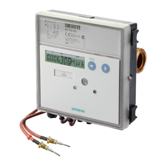
Static Heat- and Cold Meter UH50
Configuration Instructions
Static meter for Heating- and Cooling systems
UH50 ULTRAHEAT
UH50 ULTRACOLD
UH50 FLOW SENSOR
Version of firmware: 5.15 and higher
Ultraheat / Ultracold UH50
UH 106-101k
®
®
Subject to change without prior notice
issue: January 2010
UH 106-101k
Page 1 / 15
Advertisement
Table of Contents

Related Manuals for Siemens UH50 Series


Summary of Contents for Siemens UH50 Series
- Page 1 Static Heat- and Cold Meter UH50 issue: January 2010 Configuration Instructions UH 106-101k Static meter for Heating- and Cooling systems ® UH50 ULTRAHEAT ® UH50 ULTRACOLD UH50 FLOW SENSOR Version of firmware: 5.15 and higher Ultraheat / Ultracold UH50 Subject to change without prior notice UH 106-101k Page 1 / 15...
-
Page 2: Safety Information
Meter for measurement of flow and energy in a heat or cold circuit with water using the ultrasonic principle. Important properties are: • Non-wearing due to non-moving parts • Measuring range of flow 1:100 according to EN 1434, 1:1000 total range •... - Page 3 Large meters with threaded joint alternative mounting option m³/h G / DN m³/h mbar m³/h m³/h G ¾ DN20 G ¾ qp m³/h PN bar DN20 16 / 25 G 1¼ B G 1¼ B G 1¼ B DN20 G 1¼ G 2 B DN25 G 1¼...
-
Page 4: Installation
Mounting as a cold meter Installation When mounting a cold meter or combined Based on the dimension drawings, choose a heat/cold meter, make sure the black cover on the mounting location with sufficient clearance. Mount measuring tube is oriented to the side or downward the volume measuring unit between two shut-off (because of water condensation). - Page 5 Service loop (selection) Service button *) LOOP LCD button 1 advances the display to the next loop. After the last loop, the user loop (LOOP 0) appears again. LCD button 2 displays the content of the selected LCD- LCD- button 1 service loop.
-
Page 6: Resolution Of The Display
Resolution of the display $ /+ & 1 kWh $ /+ & MWh *) 0,001 MWh 0,01 MWh 1 MJ GJ *) 0,001 GJ 0,01 GJ 0,1 GJ m³/h 0,001 m³/h 0,01 m³/h m³ 0,01 m³ 0,1 m³ After the last display, the previously selected set day 2,5 3,5 15 25 is displayed again. -
Page 7: Permissible Combinations Of Modules
110 V or 230 V alternating voltage Permissible combinations of modules Voltage 85..121 V AC 196..253 V AC Type Safety class II Pulse AM = Analog Frequency 50 / 60 Hz module module Line voltage max. 10% of the nom. MB;... - Page 8 The pulse module permits the output of pulses that Pulses for quantity of energy, volume, tariff can be derived from the quantity of energy, the register volume, tariff register 1 or tariff register 2. Two Period duration > 200 ms channels are available whose functions can be Pulse duration 100 ms conducting...
- Page 9 The CL module can be used to set up a point-to- The analog module converts a selectable measured point link enabling the meter to be read remotely, for value of the meter into an analog output signal example, at the front door. (2 output signals, channel 1, channel 2).
-
Page 10: Error Messages
Supplied quantity of energy (tariff T7) In tariff register 1, a quantity of energy is summated that is calculated from the flow temperature (instead of from the temperature difference). Returned quantity of energy (tariff T8) The contents of the tariff registers are displayed in In tariff register 1, a quantity of energy is summated the user loop after the quantity of energy. -
Page 11: Log Functions
Log functions Data logger (optional) Logbook The data logger permits the archiving of data that the In the internal logbook, metrologically relevant user can select from a predefined set of values. The events (errors, states, actions) are stored in data logger contains four archives whose 8 channels chronological order with their time of occurrence. -
Page 12: Order Codes (Type Number Key)
Order codes (type number key) Nominal flowrate 1.5 m³/h, length 130mm, nominal Order codes for label plate data pressure PN16, connection G 1 1. Type of meter and mounting location Code Nominal flowrate 1.5 m³/h, length 130mm, nominal Heat meter for two wire temperature measurement pressure PN25, connection G 1 and for mounting in return Nominal flowrate 2.5 m³/h, length 130mm, nominal... - Page 13 Dial plate for Uzbekistan (Russian) Analog module in slot2 5. Manufacturer's label Code M-Bus module G4 in slot2 Logo SIEMENS CL-module in slot2 6. Sensor type and method of connection Code M-bus 30s module in slot2 Flow sensor (without temperature sensors)
- Page 14 Internet at www.siemens.com/sbt WZR-NE module WZU-AM Communication modules Code Analog module WZU-AM Siemens AG CL-Module WZU-CL Building Technologies M-Bus module acc. to DIN 1434-3 (G2- generation 2 – recommended until WZU-MB meter FW 5.14) Please contact our next sales office...
- Page 15 Ultraheat / Ultracold UH50 Configuration Instructions UH 106-101k Page 15 / 15...