Table of Contents
Advertisement
Quick Links
Advertisement
Table of Contents

Related Manuals for Siemens SIMADYN D T400


Summary of Contents for Siemens SIMADYN D T400
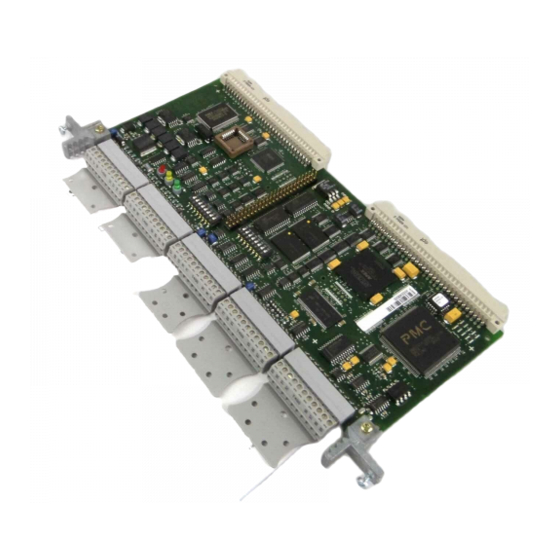
- Page 1 SIMADYN D Brief Description T400 Technology Module Edition 09.99...
- Page 2 T400 Technology Module 09.98 T400 Technology Module 04.00 Copyright © SIEMENS AG 2000 All rights reserved Disclaimer of liability The reproduction, transmission or use of this document or its We have checked the contents of this Manual to ensure that they coincide with the described hardware and software.
-
Page 3: Table Of Contents
Contents Definitions.......................... 2 Danger and warning information ..................2 1. Product description ...................... 3 2. Installation ........................4 2.1. Installing the module..................4 2.1.1. SRT400..................... 4 2.1.2. Electronics box in the MASTERDRIVE / DC MASTER ...... 4 2.2. Connections..................... 5 3. -
Page 4: Definitions
The sales contract contains the entire obligation of Siemens. The warranty contained in the contract between the parties is the sole warranty of Siemens. Any statements contained herein do not create new warranties nor modify the existing warranty. -
Page 5: Product Description
The T400 is always used in the drives and in the SRT400, together with the MASTERDRIVES or DC MASTER communications module, for example, CB1, SCB as well as the ADB carrier module with the communications modules inserted in it, for example, CBP2 (PROFIBUS-DP), CBC (CAN), CBD (DeviceNet). Siemens AG Edition 04.00 SIMADYN D Hardware Brief Description... -
Page 6: Installation
♦ Carefully locate the new module onto the guide rails and insert it fully into the electronics box. ♦ Tighten the module retaining screws above and below the handles. Edition 04.00 Siemens AG SIMADYN D Hardware Brief Description... -
Page 7: Connections
MASTER DRIVES Dual- Dual- Communic- or DC-MASTER Port- Port- ations module basic drive e.g. CB1, ADB Datei: T400-io.dsf Note: All of the grounds are connected with one another and the electronics ground. Siemens AG Edition 04.00 SIMADYN D Hardware Brief Description... - Page 8 Absolute encoder 1: data- Absolute encoder 1: clock+ Absolute encoder 1: clock- Either absolute encoder 2 or serial interface 2 can be used. The selection is made when configuring the software using CFC. Edition 04.00 Siemens AG SIMADYN D Hardware Brief Description...
- Page 9 Ser. interface 2: Tx (Rx)-RS485- 2 or 4 wire Absolute encoder 2: clock- Either absolute value encoder 2 or serial interface 2 can be used. The selection is made when configuring the software using CFC. Siemens AG Edition 04.00 SIMADYN D Hardware Brief Description...
-
Page 10: Technical Data
32 Kbyte permanent change memory • NOVRAM for data save at voltage-off for up to 10 configurable values (real type) • Cache memory: 4 Kbyte program, 4 Kbyte data • Clock cycle (external/internal): 32/32 MHz Edition 04.00 Siemens AG SIMADYN D Hardware Brief Description... -
Page 11: General Data
Max. +/- 10 mA Resolution 12 bit (4.88mV) Linearity error < 1 bit Absolute accuracy +/- 3 bit Short-circuit protection to ground Voltage rate-of-rise of the Approx. 4.2 V/µs output Delay time 3.5 µs Siemens AG Edition 04.00 SIMADYN D Hardware Brief Description... - Page 12 Switching frequency 5 kHz for ohmic loads Signal level for 0 signal Max. 0.1 V for 1 signal Power supply voltage - 0.3 V Switching delay Max. 70 µs (0V to 24V) Edition 04.00 Siemens AG SIMADYN D Hardware Brief Description...
-
Page 13: Incremental Encoder With Coarse- And Fine Pulse Evaluation
Zero pulse evaluation The zero pulse evaluation can be parameterized and is dependent on the direction of rotation, i.e. the same encoder position is identified independent of the actual direction of rotation. Siemens AG Edition 04.00 SIMADYN D Hardware Brief Description... -
Page 14: Pulse Encoder 2
The terminating resistors are switched-out in the OFF position; they are switched-in in the ON position. The switch settings can only be changed when the module is withdrawn. They are not accessible when the module is inserted. Edition 04.00 Siemens AG SIMADYN D Hardware Brief Description... -
Page 15: Useable Pulse Encoder Types
0 signal < -0.2 V for 1 signal > 0.2 V Input current Approx. 2 mA Pulse frequency Max. 1.5 MHz (track frequency) Can be configured per software (function Input filter block) Siemens AG Edition 04.00 SIMADYN D Hardware Brief Description... -
Page 16: Absolute Value Encoder
USS protocol. If the USS protocol is set, it is no longer possible to realize online visualization with CFC or service-IBS (service-start-up)! Switch S1 / 8 RS485 (2 wire) for USS protocol (bus termination, refer to 3.7.3) RS232 for service / start-up Edition 04.00 Siemens AG SIMADYN D Hardware Brief Description... -
Page 17: Connecting Cable To The Pc
3.7.4. Download switch S1/7 Switch S1 / 7 User program inhibited, only download possible. Standard operation This function will only be available from D7-SYS V4.0 R07/98, and version K of the T400. Siemens AG Edition 04.00 SIMADYN D Hardware Brief Description... -
Page 18: Diagnostic Leds
5 Hz initialization error steady light system error Data transfer to the yellow flashes: OK basic drive Data transfer to the green dark or steady light: faulted communications module Edition 04.00 Siemens AG SIMADYN D Hardware Brief Description... -
Page 19: Troubleshooting
+49 9131 98 1603 email: hotline.simadyn@erlf.siemens.de The SIMADYN D Hotline can be accessed from 8.00 to 17.00, Monday to Friday. Outside these times, you can use the telephone answering machine, fax or email. Siemens AG Edition 04.00 SIMADYN D Hardware Brief Description... -
Page 20: Parameterization
This limitation must be taken into account, if frequent write accesses, e.g. from a PLC via PROFIBUS or USS are used, e.g. with continuos commands to ‘store permanently in EEPROM’. For continuos changes the command ‘store temporary in RAM’ should be use. Edition 04.00 Siemens AG SIMADYN D Hardware Brief Description... -
Page 21: Configuring
In comparison to the configuring for the T400, when porting, only the function blocks for the input, output and communication interfaces have to be adapted to the appropriate SIMADYN D modules. Siemens AG Edition 04.00 SIMADYN D Hardware Brief Description... -
Page 22: Freely Configuring The T400
The configured software is then compiled by the CFC graphic configuring interface, and downloaded into the T400. Edition 04.00 Siemens AG SIMADYN D Hardware Brief Description... - Page 23 6DD1903-0EA0). It describes the basic steps in configuring a T400. The function blocks are described in the SIMADYN D documentation (on CD: 6DD1987-0AA2, on paper: 6DD1987-1AB2) and in the online help of D7-SYS. Siemens AG Edition 04.00 SIMADYN D Hardware Brief Description...
-
Page 24: Manufacturer's Declaration
Manufacturer’s declaration 7. Manufacturer’s declaration Edition 04.00 Siemens AG SIMADYN D Hardware Brief Description... - Page 25 Manufacturer’s declaration Siemens AG Edition 04.00 SIMADYN D Hardware Brief Description...
-
Page 26: Esd Guidelines
Modules may only be placed down on conductive surfaces (desktop with ESD surface, conductive ESD foam rubber, ESD packing bags, ESD transport containers, cardboard- or paper surfaces). Modules may not be brought close to data terminals, monitors or television sets. Edition 04.00 Siemens AG SIMADYN D Hardware Brief Description... -
Page 27: Measuring And Making Changes On Esd Modules
The necessary ESD protective measures are clearly shown in the following diagram. a = conductive flooring surface d = ESD coat/jacket b = ESD desk = ESD chain c = ESD shoes f = grounding connection for the cabinets Siemens AG Automatisation & Drives Postfach 3269, D-91050 Erlangen...