
Related Manuals for Siemens FDOOT271


Summary of Contents for Siemens FDOOT271
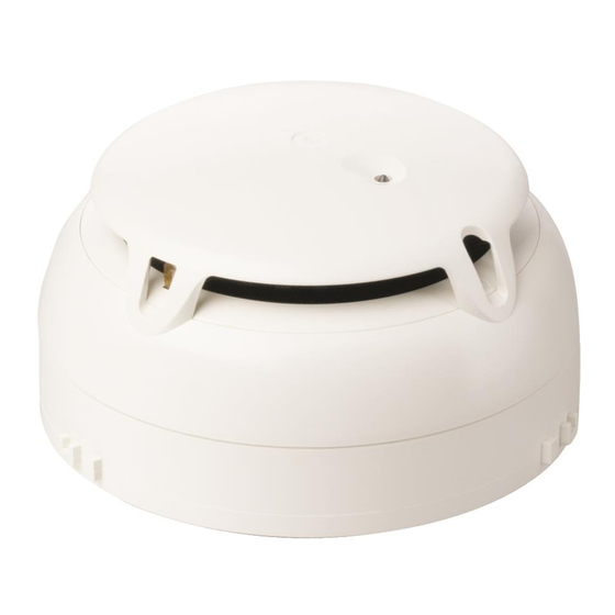
- Page 1 FDOOT271, FDB271 Radio fire detector, detector base Mounting Smart Infrastructure A6V10227637_j_en_-- 2020-03-31...
- Page 2 All rights created by patent grant or registration of a utility model or design patent are reserved. Issued by: Siemens Switzerland Ltd. Smart Infrastructure Global Headquarters Theilerstrasse 1a CH-6300 Zug Tel. +41 58 724-2424 www.siemens.com/buildingtechnologies Edition: 2020-03-31 Document ID: A6V10227637_j_en_-- © Siemens Switzerland Ltd, 2012 2 | 22 A6V10227637_j_en_--...
-
Page 3: Table Of Contents
About this document................. Applicable documents ................Mounting / Installation................Required space ..................Detector base FDB271 ................Installing the radio fire detector FDOOT271..........Detector locking device FDBZ293 ............Designation plate FDBZ291 ..............Detector dust cap FDZ291 ............... Detector base seal RS720................ Establishing factory settings .............. - Page 4 4 | 22 A6V10227637_j_en_--...
-
Page 5: About This Document
You will find information on how to integrate the radio fire detector into a radio cell in document A6V10227639 'Technical manual Radio gateway FDCW241'. Intended use The radio fire detector FDOOT271 may only be used in a detector base FDB271 and together with a radio gateway FDCW241 in a fire detection system FS20/ FS720. -
Page 6: Mounting / Installation
Mounting / Installation Required space 2 Mounting / Installation 2.1 Required space ● Upon insertion of the detector, the detector base is stressed by compression, tension and torsion. The fixing must thus be designed accordingly. ● Detector bases must be placed flat on the ceiling. ●... -
Page 7: Detector Base Fdb271
Mounting / Installation Detector base FDB271 2.2 Detector base FDB271 The detector base must be securely connected to the substructure. Screw the detector base securely onto the substructure using two screws. 46 mm 90 mm Figure 2: Mounting the detector base 1 Detector base 2 Screws with max. Ø... -
Page 8: Installing The Radio Fire Detector Fdoot271
Mounting / Installation Installing the radio fire detector FDOOT271 2.3 Installing the radio fire detector FDOOT271 The action of inserting the radio fire detector into the detector base activates it; the detector then logs on to other radio devices immediately. Therefore, start from the radio gateway and work outwards to install the individual radio fire detectors. - Page 9 Mounting / Installation Installing the radio fire detector FDOOT271 5. Make sure that the holder (3) latches into place correctly. When the battery connector is connected, the internal alarm indicator lights up red for 5 seconds. After a further 10 seconds, the radio fire detector signals that it is not installed on the detector base and the internal alarm indicator flashes.
-
Page 10: Detector Locking Device Fdbz293
Mounting / Installation Detector locking device FDBZ293 2.4 Detector locking device FDBZ293 The detector can be protected against theft with the detector locking device FDBZ293. Figure 4: Mounting of detector locking device FDBZ293 1 Detector base 4 Detector 2 Set screw with a hexagon socket 5 Allen key 3 Hole 1. -
Page 11: Designation Plate Fdbz291
Mounting / Installation Designation plate FDBZ291 2.5 Designation plate FDBZ291 Designation plate FDBZ291 is used to assign a location address to the detector. 1. Label the designation plate. 2. Slide the designation plate into the detector base from the side. FDBZ291 FDB271 Figure 5: Installing the designation plate 1 Designation plate 2 Detector base A6V10227637_j_en_--... -
Page 12: Detector Dust Cap Fdz291
Mounting / Installation Detector dust cap FDZ291 2.6 Detector dust cap FDZ291 During the construction phase the detector may be covered with a detector dust cap FDZ291 to protect it from dust and dirt. FDZ291 Figure 6: Mounting / removal of detector dust cap FDZ291 Detector Detector dust cap Removing detector dust cap by turning it to the right... -
Page 13: Detector Base Seal Rs720
Mounting / Installation Detector base seal RS720 2.7 Detector base seal RS720 ● Use the detector base seal RS720 to install point detectors in wet rooms. Protection category: IP42. ● Not compatible with designation plate FDBZ291. Installing the detector base seal 1. NOTICE! Excessively large holes in the detector base seal will impair the potential protection category. -
Page 14: Establishing Factory Settings
Mounting / Installation Establishing factory settings 2.8 Establishing factory settings All existing settings are deleted and reset to the factory settings. Figure 8: Establishing factory settings 1 Internal alarm indicator 2 'new' opening with button To create the factory settings on the radio fire detector, proceed as follows: The radio fire detector is being supplied with power. -
Page 15: Details For Ordering
Details for ordering Radio fire detector FDOOT271 3 Details for ordering 3.1 Radio fire detector FDOOT271 ● For the SWING radio fire detection system ● Attached to detector base FDB271 ● Power supplied by battery pack BAT3.6-10 ● Can be configured using MCL-USB adapter (radio) FDUZ227 with SWING tool FXS2061 ●... -
Page 16: Detector Locking Device Fdbz293
Details for ordering Detector locking device FDBZ293 3.4 Detector locking device FDBZ293 ● For protection against device theft ● Hinders unauthorized access to devices ● Compatible with: – Point detectors from the 'Sinteso' product line – Alarm sounder FDS221 – Alarm sounder with supplementary optical indication FDS229 –... -
Page 17: Detector Base Seal Rs720
Details for ordering Detector base seal RS720 3.7 Detector base seal RS720 ● For mounting in wet rooms ● Protection category IP42 ● Compatible with: – Detector base (collective) DB110 – Detector base (collective) DB110x – Detector base (collective) DB110xx –... -
Page 18: Specifications
Specifications Technical data 4 Specifications 4.1 Technical data You will find information on approvals, CE marking, and the relevant EU directives for this device (these devices) in the following document(s); see 'Applicable documents' chapter: ● Document A6V10271323 Device characteristics Response sensitivity 2.3…12 %/m Compensation speed ≤1/45 voltage increase for detection/h... - Page 19 Specifications Technical data Standards European standards ● EN 54-5 ● EN 54-7 ● EN 54-25 ● EN 54-29 ● EN 300220-2 ● EN 301489-3 ● EN 60950-1 A6V10227637_j_en_-- 19 | 22...
-
Page 20: Dimensions
Specifications Dimensions 4.2 Dimensions Radio fire detector FDOOT271 with detector base FDB271 4.3 Environmental compatibility and disposal This equipment is manufactured using materials and procedures which comply with current environmental protection standards as best as possible. More specifically, the following measures have been undertaken: ●... - Page 21 A6V10227637_j_en_-- 21 | 22...
- Page 22 © Siemens Switzerland Ltd, 2012 Issued by Siemens Switzerland Ltd Technical specifications and availability subject to change without notice. Smart Infrastructure Global Headquarters Theilerstrasse 1a CH-6300 Zug +41 58 724 2424 www.siemens.com/buildingtechnologies A6V10227637_j_en_--...