Advertisement
Available languages
Available languages
Quick Links
SIMATIC NET
Montageanleitung für/
Assembly Instructions for
SIMATIC NET
PROFIBUS
SpliTConnect System
Nachfolgend finden Sie Informationen in deutscher Sprache.
This document contains information in English.
A5E03375783A-03
© SIEMENS AG 2018
Änderungen vorbehalten
Subject to change
6GK1905-0AA00
Stand / Dated / 10.2018
Seite 3
Page 10
Advertisement

Related Manuals for Siemens SIMATIC NET PROFIBUS SpliTConnect 6GK1905-0AA00


Summary of Contents for Siemens SIMATIC NET PROFIBUS SpliTConnect 6GK1905-0AA00
- Page 1 Stand / Dated / 10.2018 Montageanleitung für/ Seite 3 Assembly Instructions for Page 10 SIMATIC NET PROFIBUS SpliTConnect System Nachfolgend finden Sie Informationen in deutscher Sprache. This document contains information in English. A5E03375783A-03 © SIEMENS AG 2018 Änderungen vorbehalten Subject to change...
-
Page 2: Wichtiger Hinweis
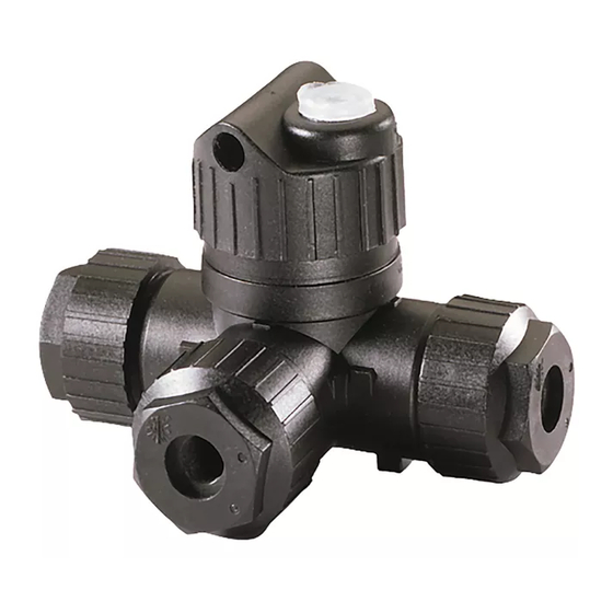
The Purchase Agreement contains the complete and exclusive obligations of Siemens. Any statements contained in this documentation do not create new warranties or restrict the existing warranty. We would further point out that, for reasons of clarity, these assembly instrucions cannot deal with every possible problem arising from the use of this device. - Page 3 Montageanleitung für SIMATIC NET PROFIBUS SpliTConnect System SpliTConnect System, Abbildung Abbildungsnmmer Bezeichnung Bestell-Nr Terminator Ex 6GK1905-0AD00 a) SpliTConnect Tap 6GK1905-0AA00 b) Kontaktierelement c) Kabelanschluss oder Blindstopfen Terminator 6GK1905-0AE00 Coupler 6GK1905-0AC00 (zur einfachen Verbindung von 2 SpliTConnect Taps) M12 Outlet 6GK1905-0AB10 (für lösbare Verbindungen mit M12 Jack) M12 Jack 6GK1905-0AF00...
- Page 4 Montageanleitung für SIMATIC NET PROFIBUS SpliTConnect System SpliTConnect System, Lieferumfang (6GK1905-0DA00) Anzahl Bezeichnung Abbildungsnummer SpliTConnact Tap Kontaktierelement Mutter M22 Zugentlastung Dichtung Schirmkontaktierelement Litzenhalter Dichtscheibe SpliTConnect Clip siehe Abbildung (Seite 3) Hinweis Vom Zubehör des SpliTConnect Systems (mit Ausnahme des Terminator Ex) besteht keine Zündgefahr und ist somit nicht Bestandteil der Zündschutzart „Eigensicherheit“.
- Page 5 Montageanleitung für SIMATIC NET PROFIBUS SpliTConnect System Vorsicht Montage Die Montage von Komponenten des SpliTConnect Tap Systems darf nur an Bussegmenten erfolgen, die nicht in Betrieb sind. Andernfalls kann es zu Unfällen oder zu Funktionsstörungen kommen. Das SpliTConnect Tap System ist nur für die Verwendung mit den SIMATIC NET PROFIBUS FC Process Cable bestimmt (Bestellnummer 6XV1830-5EH10, 6XV1830-5FH10).
- Page 6 Montageanleitung für SIMATIC NET PROFIBUS SpliTConnect System Montage des SpliTConnect Tap 1. Schrauben Sie das Kontaktier- 2. Isolieren Sie die Leitung mit Hilfe 3. Halten Sie die Abisoliermaße element (2) los und ziehen Sie des FastConnect Stripping ein. es vom SpliTConnect Tap (1) Tool Achtung! Die Adern dürfen nicht abisoliert werden.
- Page 7 Montageanleitung für SIMATIC NET PROFIBUS SpliTConnect System Montage nicht benutzter Ausgänge 1. Schließen Sie nicht benutzte Ausgänge mit Mutter (3), Dichtung (5). Dichtscheibe (8), Schirmkontaktierelement (6) und Litzenhalter (7) Achten Sie dabei auf die Reihenfolge. Montage auf einer Fläche oder Hutschiene 1.
- Page 8 Montageanleitung für SIMATIC NET PROFIBUS SpliTConnect System Montage des SpliTConnect M12 Outlet 1. Schrauben Sie das SpliTConnect M12 Outlet (11) auf einen freien Leitungsabgang eines SpliTConnect Tap (1) auf. Achtung! Das Kontaktierelement (2) muss demontiert sein 2. Schrauben Sie das Kontaktierelement (2) auf den komplett bestückten SpliTConnect Tap (1) auf.
- Page 9 Montageanleitung für SIMATIC NET PROFIBUS SpliTConnect System Technische Daten des SpliTConnect System Elektrische Daten Gemäß PROFIBUS-Spezifikation IEC 61158-2 Datenrate 31,25 kbit/s Anschlusstechnik Schneidklemmtechnik Kontaktierhäufigkeit 4 mal Kabeldurchführung Erdanschluss Schutzart IP67 Gehäusewerkstoff PBT mit 10% GF + 10% CF Schockbeanspruchung 30g / 11ms Schwingbeanspruchung 10 …...
- Page 10 Assembly Instructions for SIMATIC NET PROFIBUS SpliTConnect System SpliTConnect System, schematic Figure number Name Order no. Terminator Ex 6GK1905-0AD00 a) SpliTConnect Tap 6GK1905-0AA00 b) Contacting element c) Cable connector or dummy plug Terminator 6GK1905-0AE00 Coupler 6GK1905-0AC00 (for single connection of 2 SpliTConnect taps) M12 Outlet 6GK1905-0AB10 (for pluggable connections with M12 jack)
- Page 11 Assembly Instructions for SIMATIC NET PROFIBUS SpliTConnect System SpliTConnect System, components of the product (6GK1905-0DA00) Number Name Number in schematic SpliTConnect Tap Contacting element Nut M22 Strain relief Seal Shield contact element Strand holder Sealing washer SpliTConnect Clip refer figure (page 10) Note The accessories of the SpliTConnect system (with the exception of the Terminator Ex) do not represent any ignition risk and are therefore not included in the type of protection "intrinsic safety".
- Page 12 Assembly Instructions for SIMATIC NET PROFIBUS SpliTConnect System Caution Assembly Components of the SpliTConnect tap system must only be assembled in bus segments that are not operational. Otherwise accidents or functional disruptions are possible. The SpliTConnect tap system is intended only for use with the SIMATIC NET PROFIBUS FC process cable (order number 6XV1830-5EH10, 6XV1830-5FH10).
- Page 13 Assembly Instructions for SIMATIC NET PROFIBUS SpliTConnect System Assembling the SpliTConnect tap 1. Unscrew the contacting element 2. Strip the cable with the 3. Keep to the stripping lengths. (2) and pull it away from the FastConnect stripping Caution! The wires must not be SpliTConnect tap (1).
- Page 14 Assembly Instructions for SIMATIC NET PROFIBUS SpliTConnect System Assembling unused outputs 1. Close unused outputs with nut (3), seal (5), sealing washer (8), shield contact element (6) and strand holder (7). Make sure they are fitted in the correct order. Installation on a surface or DIN rail 1.
- Page 15 Assembly Instructions for SIMATIC NET PROFIBUS SpliTConnect System Fitting the SpliTConnect M12 outlet 1. Screw the SpliTConnect M12 Outlet (11) onto a free cable outlet of a SpliTConnect tap (1). Caution! The contacting element (2) must first be removed 2. Screw the contacting element (2) onto the completely assembled SpliTConnect tap (1).
- Page 16 Assembly Instructions for SIMATIC NET PROFIBUS SpliTConnect System Technical specifications of the SpliTConnect system Electrical data Complying with PROFIBUS Specification IEC 61158-2 Data rate 31.25 Kbps Connector technology Insulation piercing technique Contacting cycles 4 times Cable feedthrough Ground connection Degree of protection IP67 Housing material PBT with 10% GF + 10% CF...