
Related Manuals for Huawei TaiShan 2280 V2


Summary of Contents for Huawei TaiShan 2280 V2
-
Page 1: User Guide
TaiShan 2280 V2 Server V100R001 User Guide Issue Date 2019-07-01 HUAWEI TECHNOLOGIES CO., LTD. - Page 2 Notice The purchased products, services and features are stipulated by the contract made between Huawei and the customer. All or part of the products, services and features described in this document may not be within the purchase scope or the usage scope. Unless otherwise specified in the contract, all statements, information, and recommendations in this document are provided "AS IS"...
-
Page 3: About This Document
2280 V2, and how to install an OS, replace parts, and install, remove, configure, and troubleshoot the server. You can perform installation, removal, power-on, power-off, basic configuration, OS installation, parts replacement, and troubleshooting of the TaiShan 2280 V2 by referring to this document. Intended Audience... -
Page 4: Change History
NOTE is used to address information not related to personal injury, equipment damage, and environment deterioration. Change History Issue Date Description 2019-07-01 This issue is the first official release. Issue 01 (2019-07-01) Copyright © Huawei Technologies Co., Ltd. -
Page 5: Table Of Contents
3.6 Removing the Chassis Cover............................37 3.7 Installing the Chassis Cover............................37 3.8 Removing a Fan Module.............................. 38 3.9 Installing a Fan Module..............................39 3.10 Removing the Air Duct...............................40 3.11 Installing the Air Duct..............................42 Issue 01 (2019-07-01) Copyright © Huawei Technologies Co., Ltd. - Page 6 5.3 Drive..................................... 87 5.3.1 Removing a Drive..............................87 5.3.2 Installing a Drive............................... 88 5.4 AC PSU..................................89 5.5 PCIe Card on a Riser Card............................91 5.6 Screw-in RAID Controller Card...........................92 5.7 Supercapacitor................................94 Issue 01 (2019-07-01) Copyright © Huawei Technologies Co., Ltd.
- Page 7 12 Preventing Electrostatic Discharge..................138 12.1 Operation Instructions.............................. 138 12.2 ESD Wrist Strap................................139 13 Product Specifications......................140 13.1 Technical Specifications............................140 13.2 Environmental Specifications...........................142 13.3 Physical Specifications............................. 144 13.4 PSU Specifications..............................145 14 Common Operations.......................146 Issue 01 (2019-07-01) Copyright © Huawei Technologies Co., Ltd.
- Page 8 14.5 Logging In to the Server over a Network Port Using PuTTY..................159 15 Support and Other Resources....................162 15.1 Technical Support..............................162 A Appendix............................164 A.1 Logical Structure............................... 164 A.2 Glossary..................................165 A.3 Acronyms and Abbreviations............................ 166 Issue 01 (2019-07-01) Copyright © Huawei Technologies Co., Ltd.
-
Page 9: Overview
1 Overview Overview The TaiShan 2280 V2 server is a 2 U 2-socket rack server developed based on Huawei Kunpeng 920 processors. It features high-performance computing, large-capacity storage, low power consumption, easy management, and easy deployment and is ideal for Internet, distributed storage, cloud computing, Big Data, and enterprise services. -
Page 10: Components
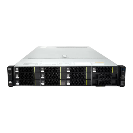
2.10 Riser Cards and PCIe Slots 2.11 Fan Modules 2.12 Physical Structure 2.1 Front Panel Components Figure 2-1 shows the components on the front panel of a server with 12 x 3.5-inch drives. Issue 01 (2019-07-01) Copyright © Huawei Technologies Co., Ltd. - Page 11 Figure 2-3 Components on the front panel of a server with 8 x 2.5-inch SAS/SATA drives and 12 x 2.5-inch NVMe SSDs Drive Filler panel VGA port USB 3.0 port Label plate with an SN label Issue 01 (2019-07-01) Copyright © Huawei Technologies Co., Ltd.
-
Page 12: Port Type
Description SN ID (two characters), which is 21. Material identification code (eight characters), that is, processing code. Vendor code (two characters). The value 10 indicates Huawei and other values indicate outsourcing vendors. Issue 01 (2019-07-01) Copyright © Huawei Technologies Co., Ltd. -
Page 13: Front Panel Indicators And Buttons
4 Fault diagnostic LED 5 FlexIO presence indicators (1 and 2) Figure 2-6 shows the indicators and buttons on the front panel of a server with 25 x 2.5- inch drives. Issue 01 (2019-07-01) Copyright © Huawei Technologies Co., Ltd. - Page 14 Table 2-3 Indicators and buttons on the front panel Silkscre Indicator/ State Description Button Fault l ---: The server is operating normally. diagnostic l Error code: A server component is faulty. Issue 01 (2019-07-01) Copyright © Huawei Technologies Co., Ltd.
- Page 15 1 and 2: The numbers 1 and 2 respectively represent the presence two FlexIOs. indicators (1 l Steady green: The FlexIO is properly connected. and 2) l Off: The FlexIO is faulty or not in use. Issue 01 (2019-07-01) Copyright © Huawei Technologies Co., Ltd.
-
Page 16: Rear Panel Components
FlexIO 1 or 2 is not hot-swappable. If you need to replace it, power off the server. Table 2-4 Ports on the rear panel Port Type Quantit Description VGA port DB15 The VGA port is connected to a terminal, such as a monitor or KVM. Issue 01 (2019-07-01) Copyright © Huawei Technologies Co., Ltd. -
Page 17: Rear Panel Indicators
2.4 Rear Panel Indicators Figure 2-9 shows the indicators on the rear panel of the server. Figure 2-9 Rear panel indicators 1 PSU indicator 2 GE electrical port connection status indicator Issue 01 (2019-07-01) Copyright © Huawei Technologies Co., Ltd. -
Page 18: Flexio
Blinking green at 4 Hz: under online PSU firmware upgrade. l Off: No AC power is supplied. 2.5 FlexIO For details about FlexIOs supported by the server, see the Intelligent Computing Compatibility Checker. Issue 01 (2019-07-01) Copyright © Huawei Technologies Co., Ltd. -
Page 19: Mainboard And Ibmc Card Connectors
Steady green: The network port is indicator properly connected. l Off: The network port is not connected. 2.6 Mainboard and iBMC Card Connectors Figure 2-11 shows connectors on the mainboard and iBMC card. Issue 01 (2019-07-01) Copyright © Huawei Technologies Co., Ltd. - Page 20 19 Front drive backplane power signal connector 20 Front drive backplane power signal connector 2 (J5) 1 (J47) 21 Left mounting ear connector (J92) 22 Rear drive backplane 3 low-speed signal connector (J67) Issue 01 (2019-07-01) Copyright © Huawei Technologies Co., Ltd.
-
Page 21: Drive Backplane Connectors
Figure 2-13 Backplane for 12 x 3.5-inch drives in Expander mode (BOM 03024MSG) 1 Indicator signal cable connector (J32) 2 mini-SAS HD connector (PORT A/J28) 3 mini-SAS HD connector (PORT B/J29) 4 mini-SAS HD connector (REAR PORT/J31) Issue 01 (2019-07-01) Copyright © Huawei Technologies Co., Ltd. - Page 22 7 Indicator signal cable connector (J41) Power connector (J37) 9 Slimline connector (PORT 2A/J21) 10 Slimline connector (PORT 2B/J32) Figure 2-16 shows connectors on the backplane for two 3.5-inch rear drives. Issue 01 (2019-07-01) Copyright © Huawei Technologies Co., Ltd.
- Page 23 2.5-inch rear drives. Figure 2-18 Backplane for four 2.5-inch rear drives (BOM 03025VYV) 1 Power connector (REAR BP POWR3/J24) 2 Slimline A connector (SLIMLINE A/J8) Issue 01 (2019-07-01) Copyright © Huawei Technologies Co., Ltd.
-
Page 24: Dimm Slot Locations
2.9.1 Drive Slot Numbers Figure 2-20 shows the drive slot numbers of a server with 12 x 3.5-inch drives in Expander mode. Figure 2-20 Server with 12 x 3.5-inch drives in Expander mode Issue 01 (2019-07-01) Copyright © Huawei Technologies Co., Ltd. - Page 25 Table 2-8 Drive slot numbers of a server with 25 x 2.5-inch drives in Expander mode Physical Slot Number Slot Number Identified Slot Number Identified by iBMC by RAID Controller Disk40 Issue 01 (2019-07-01) Copyright © Huawei Technologies Co., Ltd.
- Page 26 : 4 (NVMe SSDs) Server with 12 x 12 (SAS/SATA 1. I/O module 2: 2 (SAS/SATA CPU over 3.5-inch drives in drives) drives) pass-through 2. I/O module 3 : 4 (NVMe mode SSDs) Issue 01 (2019-07-01) Copyright © Huawei Technologies Co., Ltd.
-
Page 27: Sas/Sata Drive Indicators
Blinking at 1 Hz The data on the secondary drive is being rebuilt. Steady on A member drive in the RAID array is removed. Steady on Steady on The drive is faulty. Issue 01 (2019-07-01) Copyright © Huawei Technologies Co., Ltd. -
Page 28: Nvme Ssd Indicators
Figure 2-29, and Figure 2-30 show riser cards supported by I/O modules 1 and 2 in a TaiShan 2280 V2. The riser card shown in Figure 2-26 can be installed in I/O module 1 or 2. It provides PCIe slots 1 to 3 when installed in I/O module 1 and PCIe slots 4 to 6 when installed in I/O module 2. - Page 29 I/O module 2. NOTE l This card must be used together with the power cable provided by Huawei. l Only slots 2 and 5 support full-height full-length dual-width GPUs. Figure 2-27 Riser card 2 (one x8 slot and one x16 slot)
- Page 30 I/O module 2 by default. When installed in I/O module 1, it occupies PCIe slots 1 to 3 and only slot 3 (x8) is available. When installed in I/O module 2, it occupies PCIe slots 4 to 6 and only slot 6 (x8) is available. Issue 01 (2019-07-01) Copyright © Huawei Technologies Co., Ltd.
- Page 31 Figure 2-31 provides PCIe slots 7 and 8 Figure 2-31 Riser card 6 (two x8 slots) When installed in I/O module 3, the riser card shown in Figure 2-32 provides PCIe slot Issue 01 (2019-07-01) Copyright © Huawei Technologies Co., Ltd.
- Page 32 Figure 2-32 Riser card 7 (one x16 slot) Figure 2-33 shows the rear PCIe slots of the TaiShan 2280 V2. Figure 2-33 PCIe slots I/O module 1 provides slots 1 to 3, I/O module 2 provides slots 4 to 6, and I/O module 3 provides slots 7 and 8.
- Page 33 3-slot PRM: x8 Slot l Single-slot Port 80/08/0 83/00/0 Full-height PRM: N/A half-length l 2-slot PRM: x8 l Single-slot Slot Port 80/0C/0 84/00/0 Full-height PRM: x16 half-length l 2-slot PRM: x8 Issue 01 (2019-07-01) Copyright © Huawei Technologies Co., Ltd.
-
Page 34: Fan Modules
The fan speed can be adjusted. In normal cases, the fans run at the minimum speed. If the server temperature increases, the speed will increase accordingly. Figure 2-34 shows the fan modules. Issue 01 (2019-07-01) Copyright © Huawei Technologies Co., Ltd. -
Page 35: Physical Structure
TaiShan 2280 V2 Server User Guide 2 Components Figure 2-34 Fan modules 2.12 Physical Structure Figure 2-35 shows the components of a server with 12 drives. Issue 01 (2019-07-01) Copyright © Huawei Technologies Co., Ltd. - Page 36 I/O modules 1, 2, and 3 can be drive modules or riser modules. The preceding figure is for reference only. l CPUs are integrated on the mainboard and cannot be replaced independently. Issue 01 (2019-07-01) Copyright © Huawei Technologies Co., Ltd.
-
Page 37: Basic Operations
PSUs. To change the value of System State Upon Power Supply, log in to the iBMC WebUI and choose Power > Power Control. Issue 01 (2019-07-01) Copyright © Huawei Technologies Co., Ltd. -
Page 38: Powering Off The Server
2.2 Front Panel Indicators and Buttons. Power off the server using the iBMC WebUI. Log in to the iBMC WebUI. For details, see 4.6.4 Logging In to the iBMC WebUI. Choose Power > Power Control. Issue 01 (2019-07-01) Copyright © Huawei Technologies Co., Ltd. -
Page 39: Removing The Server And Guide Rails
Step 2 Power off the server. For details, see 3.2 Powering Off the Server. Step 3 Disconnect all power cables and signal cables from the server. Step 4 Remove the server. Issue 01 (2019-07-01) Copyright © Huawei Technologies Co., Ltd. - Page 40 Pull out the server from the cabinet along the guide rails away. See (2) in Figure 3-1. Place the removed server on an ESD platform. Step 5 Remove the screws that secure a guide rail. See Figure 3-2. Figure 3-2 Removing an L-shaped guide rail Issue 01 (2019-07-01) Copyright © Huawei Technologies Co., Ltd.
-
Page 41: Removing The Server And Adjustable Guide Rails
Step 6 Remove the two plugs from the middle square holes on both ends. See (2) in Figure 3-4. Step 7 Slightly lift the guide rail, retract it from the square holes, and take it out. See (3) and (4) in Figure 3-4. Issue 01 (2019-07-01) Copyright © Huawei Technologies Co., Ltd. -
Page 42: Removing Cables From A Psu
PSU is operating properly and its power rating is greater than or equal to the power rating of the server. Step 4 Undo the velcro strap that secures the power cable. See Figure 3-5. Issue 01 (2019-07-01) Copyright © Huawei Technologies Co., Ltd. -
Page 43: Connecting Cables To A Psu
Step 5 Remove the power cable from the PSU to be replaced. See Figure 3-6. Figure 3-6 Removing a power cable ----End 3.5 Connecting Cables to a PSU Step 1 Wear an ESD wrist strap. For details, see 12 Preventing Electrostatic Discharge. Issue 01 (2019-07-01) Copyright © Huawei Technologies Co., Ltd. - Page 44 Figure 3-8 Securing a power cable Step 4 Log in to the iBMC WebUI, and check whether the new component is normal. For details, see TaiShan Rack Server iBMC User Guide. ----End Issue 01 (2019-07-01) Copyright © Huawei Technologies Co., Ltd.
-
Page 45: Removing The Chassis Cover
Step 1 Wear an ESD wrist strap. For details, see 12 Preventing Electrostatic Discharge. Step 2 Aligning the cover with the fixing slots on chassis walls, put it down and close the handle. See (1) and (2) in Figure 3-10. Issue 01 (2019-07-01) Copyright © Huawei Technologies Co., Ltd. -
Page 46: Removing A Fan Module
Server. Step 3 Remove the power cables. For details, see 3.4 Removing Cables from a PSU. Step 4 Remove the server. For details, see 3.3 Removing the Server and Guide Rails. Issue 01 (2019-07-01) Copyright © Huawei Technologies Co., Ltd. -
Page 47: Installing A Fan Module
Step 7 Insert the fan module along the guide rails into the slot until you hear a click. Check that the fan cable connector is securely inserted into the mainboard connector. See Figure 3-12. Issue 01 (2019-07-01) Copyright © Huawei Technologies Co., Ltd. -
Page 48: Removing The Air Duct
12 Preventing Electrostatic Discharge. Step 2 Power off the server. For details, see 3.2 Powering Off the Server. Step 3 Remove the power cables. For details, see 3.4 Removing Cables from a PSU. Issue 01 (2019-07-01) Copyright © Huawei Technologies Co., Ltd. - Page 49 Step 7 If the server is configured with a supercapacitor, disconnect the supercapacitor from the RAID. See Figure 3-13. Figure 3-13 Removing the supercapacitor cable Step 8 Lift the air duct according to the signs on the air duct. See Figure 3-14. Issue 01 (2019-07-01) Copyright © Huawei Technologies Co., Ltd.
-
Page 50: Installing The Air Duct
Step 8 Align the positioning pins on the air duct with the fixing holes on the chassis according to the instructions on the air duct. Vertically place the air duct downwards. See Figure 3-15. Issue 01 (2019-07-01) Copyright © Huawei Technologies Co., Ltd. - Page 51 Step 10 If a server is configured with a full-height full-length riser card tray, you need to install the full-height full-length riser card tray. For details, see 3.13 Installing a Riser Card Tray. Issue 01 (2019-07-01) Copyright © Huawei Technologies Co., Ltd.
-
Page 52: Removing A Riser Card Tray
Step 6 For riser module 1 or 2, remove the screw that secures the riser card tray and lift the tray. See Figure 3-17 Figure 3-18. Figure 3-17 Removing the riser card tray of riser module 1 Issue 01 (2019-07-01) Copyright © Huawei Technologies Co., Ltd. - Page 53 Step 7 For riser module 3, remove the screw that secures the upper riser card tray and lift the tray. Figure 3-19. Then remove the lower riser card tray. See Figure 3-20. Figure 3-19 Removing the upper riser card tray of riser module 3 Issue 01 (2019-07-01) Copyright © Huawei Technologies Co., Ltd.
- Page 54 Step 10 Place the removed PCIe cards and riser card tray in ESD bags. Step 11 If you do not want to install another riser card tray immediately, install a filler panel. See Figure 3-22, Figure 3-23, or Figure 3-24. Issue 01 (2019-07-01) Copyright © Huawei Technologies Co., Ltd.
- Page 55 TaiShan 2280 V2 Server User Guide 3 Basic Operations Figure 3-22 Installing a filler panel (1) Figure 3-23 Installing a filler panel (2) Issue 01 (2019-07-01) Copyright © Huawei Technologies Co., Ltd.
-
Page 56: Installing A Riser Card Tray
3.3 Removing the Server and Guide Rails. Step 5 Remove the chassis cover. For details, see 3.6 Removing the Chassis Cover. Step 6 Remove the filler panel. See Figure 3-25, Figure 3-26, or Figure 3-27. Issue 01 (2019-07-01) Copyright © Huawei Technologies Co., Ltd. - Page 57 TaiShan 2280 V2 Server User Guide 3 Basic Operations Figure 3-25 Removing a filler panel (1) Figure 3-26 Removing a filler panel (2) Issue 01 (2019-07-01) Copyright © Huawei Technologies Co., Ltd.
- Page 58 5.5 PCIe Card on a Riser Card. Step 9 For riser module 1 or 2, place the riser card tray in the slot and tighten the screw. See Figure 3-28 Figure 3-29. Issue 01 (2019-07-01) Copyright © Huawei Technologies Co., Ltd.
- Page 59 TaiShan 2280 V2 Server User Guide 3 Basic Operations Figure 3-28 Installing the riser card tray of riser module 1 Figure 3-29 Installing the riser card tray of riser module 2 Issue 01 (2019-07-01) Copyright © Huawei Technologies Co., Ltd.
- Page 60 Figure 3-30 Installing the lower riser card tray of riser module 3 Figure 3-31 Installing the upper riser card tray of riser module 3 Step 11 Install the chassis cover. For details, see 3.7 Installing the Chassis Cover. Issue 01 (2019-07-01) Copyright © Huawei Technologies Co., Ltd.
- Page 61 3.1 Powering On the Server. Step 15 Log in to the iBMC WebUI, and check whether the new component is normal. For details, see TaiShan Rack Server iBMC User Guide. ----End Issue 01 (2019-07-01) Copyright © Huawei Technologies Co., Ltd.
-
Page 62: Setup
The server draws in cool air from the front of the cabinet and exhausts hot air from the rear. Therefore, the front and rear of the cabinet must be well ventilated for optimal heat dissipation. Figure 4-1 shows the direction of heat dissipation. Issue 01 (2019-07-01) Copyright © Huawei Technologies Co., Ltd. -
Page 63: Temperature And Humidity Requirements
Complies with International Electrotechnical Commission 297 (IEC 297). Air filters installed on cabinet doors. AC power supplied from the rear of the cabinet. 4.2 Unpacking the Chassis Step 1 Check that the packaging is in good condition. Issue 01 (2019-07-01) Copyright © Huawei Technologies Co., Ltd. -
Page 64: Installing Optional Parts
4.4.1 Installing with L-Shaped Guide Rails L-shaped guide rails are designed for Huawei cabinets. The TaiShan 2280 V2 servers are stackable when L-shaped guide rails are used. Step 1 Install the floating nuts. Determine the installation positions according to the cabinet device installation plan. - Page 65 Step 2 Install the L-shaped guide rails. Position a guide rail horizontally in contact with the mounting bars in the cabinet. Tighten the screws to secure the guide rail. See Figure 4-4. Issue 01 (2019-07-01) Copyright © Huawei Technologies Co., Ltd.
- Page 66 When the two mounting ears of the server come into contact with the mounting bars on the cabinet, tighten their captive screws to secure the server. See (2) in Figure 4-5. Issue 01 (2019-07-01) Copyright © Huawei Technologies Co., Ltd.
-
Page 67: Installing With Adjustable Guide Rails
Adjustable guide rails are for a cabinet with a depth of 543.5 mm to 848.5 mm (21.40 in. to 33.41 in.) between the front and rear mounting bars. The TaiShan 2280 V2 servers are stackable onto adjustable guide rails. Step 1 Install the adjustable guide rails. -
Page 68: Connecting External Cables
30 mm (1.18 in.) when you lay out the cables in parallel. If you cannot identify cables according to the cable labels, attach an engineering label to each cable. Issue 01 (2019-07-01) Copyright © Huawei Technologies Co., Ltd. -
Page 69: Connecting Cables To A Mouse, Keyboard, And Vga Port
Step 4 Connect the DB15 connector on the VGA cable to the VGA port on the front or rear panel of the server and tighten the two screws. Step 5 Connect the other end of the VGA cable to the VGA port on the monitor and tighten the two screws. Issue 01 (2019-07-01) Copyright © Huawei Technologies Co., Ltd. -
Page 70: Connecting A Network Cable
The minimum bend radius of a network cable is 4 cm (1.57 in.). Check that the cable insulation layer is intact. Ensure that cables are routed for easy maintenance and capacity expansion. Issue 01 (2019-07-01) Copyright © Huawei Technologies Co., Ltd. -
Page 71: Connecting A Usb Device
4.5.4 Connecting a USB Device Step 1 Wear an ESD wrist strap. For details, see 12 Preventing Electrostatic Discharge. Step 2 Connect a USB device to a USB port on the server. See Figure 4-10. Issue 01 (2019-07-01) Copyright © Huawei Technologies Co., Ltd. -
Page 72: Connecting A Serial Cable
Procedure Step 1 Wear an ESD wrist strap. For details, see 12 Preventing Electrostatic Discharge. Step 2 Plug the connector into the serial port. See Figure 4-11. Issue 01 (2019-07-01) Copyright © Huawei Technologies Co., Ltd. -
Page 73: Connecting Power Cables
Ground cable The TaiShan 2280 V2 server does not provide a separate ground port. It is grounded through the ground cable of a power cable. Ensure that the power cables of the PSUs are in good contact. -
Page 74: Initial Configuration
User name: Administrator data l Password: Admin@9000 password BIOS data Password Admin@9000 iBMC U-Boot Password Admin@9000 data 4.6.2 Configuration Process Figure 4-12 shows the initial configuration process of the TaiShan 2280 V2. Issue 01 (2019-07-01) Copyright © Huawei Technologies Co., Ltd. - Page 75 Check that the server version information is correct. l Check that no alarm is generated for the server. Change the initial l Change the iBMC user name and password for the server. passwords. l Change the U-Boot password. Issue 01 (2019-07-01) Copyright © Huawei Technologies Co., Ltd.
-
Page 76: Querying The Management Network Port Ip Address
Step 2 Connect a monitor via VGA cable. Step 3 Restart the OS. Step 4 When the screen shown in Figure 4-13 is displayed, press Delete or F4 to enter the BIOS Setup screen. Issue 01 (2019-07-01) Copyright © Huawei Technologies Co., Ltd. - Page 77 The default password for logging in to the BIOS is Admin@9000. Step 6 Choose Advanced > IPMI iBMC Configuration > IBMC Config, and press Enter. The IBMC Config screen is displayed. See Figure 4-14 Figure 4-15. Issue 01 (2019-07-01) Copyright © Huawei Technologies Co., Ltd.
- Page 78 TaiShan 2280 V2 Server User Guide 4 Setup Figure 4-14 IBMC Config screen 1 Figure 4-15 IBMC Config screen 2 ----End Issue 01 (2019-07-01) Copyright © Huawei Technologies Co., Ltd.
-
Page 79: Logging In To The Ibmc Webui
If the message "There is a problem with this website's security certificate" is displayed, click Continue to this website (not recommended). l If the system displays the Security Alert dialog box indicating a certificate error, click Yes. Issue 01 (2019-07-01) Copyright © Huawei Technologies Co., Ltd. -
Page 80: Checking The Server
If the login is successful, the Information Summary page is displayed, showing the user name in the upper right corner. ----End 4.6.5 Checking the Server Check the TaiShan 2280 V2 in the sequence shown in Figure 4-18. The method to be used depends on the actual situation. - Page 81 For details, see 4.6.6 Changing Initial Passwords. Choose System > Firmware Upgrade, and view the version information, as shown Figure 4-19. Check that the TaiShan 2280 V2 versions meet site requirements. Issue 01 (2019-07-01) Copyright © Huawei Technologies Co., Ltd.
- Page 82 The SSH service is enabled by default. If the SSH service is disabled, enable it by choosing Configuration > Services on the iBMC WebUI. View the TaiShan 2280 V2 version information. Check that the TaiShan 2280 V2 versions meet site requirements. iBMC:/->ipmcget -d ver ------------------- iBMC INFO ------------------- IPMC CPU: Hi1710 IPMI Version: 2.0...
-
Page 83: Changing Initial Passwords
TaiShan 2280 V2 BIOS Version: BIOS version of the TaiShan 2280 V2 Active iBMC Version: active iBMC version of the TaiShan 2280 V2 Backup iBMC Version: backup iBMC version of the TaiShan 2280 V2 Query the health status of the TaiShan 2280 V2. - Page 84 – Lowercase letters: a to z – Uppercase letters: A to Z – Digits: 0 to 9 Cannot be the same as the user name or user name in reverse order. ----End Issue 01 (2019-07-01) Copyright © Huawei Technologies Co., Ltd.
- Page 85 Erasing Flash..done Erased 1 sectors Writing to Flash... done . done Protected 1 sectors password be changed successfully. Step 10 Run the following command to exit U-Boot: boot ----End Issue 01 (2019-07-01) Copyright © Huawei Technologies Co., Ltd.
-
Page 86: Configuring Raid
TaiShan Server RAID Controller Card User Guide. ----End 4.6.8 Configuring the BIOS Figure 4-23 shows the process for configuring the BIOS. NOTE For details, see the TaiShan V2 Server BIOS Parameter Reference. Issue 01 (2019-07-01) Copyright © Huawei Technologies Co., Ltd. -
Page 87: Restart The Server
Step 3 Select Reset. The system displays "Are you sure to perform this operation?" Step 4 Click Yes. The server restarts. Step 5 Press Delete on the startup screen shown in Figure 4-24. Issue 01 (2019-07-01) Copyright © Huawei Technologies Co., Ltd. - Page 88 The system will be locked if incorrect passwords are entered three consecutive times. Restart the server to unlock it. ----End Set the server boot priority Step 1 Press ← and → to switch to the Boot screen, as shown in Figure Boot screen. Issue 01 (2019-07-01) Copyright © Huawei Technologies Co., Ltd.
- Page 89 The Save Configuration&Exit dialog box is displayed. Step 5 Select Yes and press Enter. ----End Set the BIOS password Step 1 Press ← or → to select the Security menu, as shown in Figure 4-26. Issue 01 (2019-07-01) Copyright © Huawei Technologies Co., Ltd.
-
Page 90: Installing An Os
The server is compatible with different types of OSs. Use the Intelligent Computing Compatibility Checker to check compatible OSs. The installation method varies according to the OS type. For details, see the installation guide of each OS. Issue 01 (2019-07-01) Copyright © Huawei Technologies Co., Ltd. -
Page 91: Optional Part Installation
Read relevant installation procedures before installing multiple components to streamline identical steps. Wait until overheating devices have cooled down before touching them to avoid injury. Properly ground the server before installation to avoid damage to electronic components from electrostatic discharge. Issue 01 (2019-07-01) Copyright © Huawei Technologies Co., Ltd. -
Page 92: Front Bezel (Optional)
The front bezel is unlocked when delivered, and the key is in the inner side of the front bezel. Figure 5-1 Unlocking the front bezel Step 3 Press the securing button and remove the front bezel. See Figure 5-2. Issue 01 (2019-07-01) Copyright © Huawei Technologies Co., Ltd. -
Page 93: Installing The Front Bezel
Step 2 Hook the front bezel onto the side of the left mounting ear, and press the button to secure it to the chassis. See Figure 5-3. NOTE The front bezel is optional and can be selected as required. Issue 01 (2019-07-01) Copyright © Huawei Technologies Co., Ltd. - Page 94 5 Optional Part Installation Figure 5-3 Installing the front bezel Step 3 Lock the front bezel by turning the key counterclockwise and remove the key. See Figure 5-4. Figure 5-4 Locking the front bezel Issue 01 (2019-07-01) Copyright © Huawei Technologies Co., Ltd.
-
Page 95: Drive
For details, see 5.2.1 Removing the Front Bezel. Step 3 Press the ejector release button on the drive. See (1) in Figure 5-5. The ejector lever automatically ejects. Figure 5-5 Removing a drive Issue 01 (2019-07-01) Copyright © Huawei Technologies Co., Ltd. -
Page 96: Installing A Drive
Step 4 Take a spare drive out of its ESD bag. Step 5 Fully open the ejector lever and push the drive into the chassis along the guide rails as far as it will go. See (1) in Figure 5-6. Issue 01 (2019-07-01) Copyright © Huawei Technologies Co., Ltd. -
Page 97: Ac Psu
Ground equipment before powering it on. Otherwise, high leakage current may cause equipment damage. Step 1 Wear an ESD wrist strap. For details, see 12 Preventing Electrostatic Discharge. Step 2 Remove the PSU filler. See Figure 5-7. Issue 01 (2019-07-01) Copyright © Huawei Technologies Co., Ltd. - Page 98 3.5 Connecting Cables to a PSU. Step 6 Log in to the iBMC WebUI, and check whether the new component is normal. For details, see TaiShan Rack Server iBMC User Guide. ----End Issue 01 (2019-07-01) Copyright © Huawei Technologies Co., Ltd.
-
Page 99: Pcie Card On A Riser Card
Step 8 Take a spare PCIe card out of its ESD bag. Step 9 Insert the PCIe card into a PCIe slot. See (1) in Figure 5-10. Step 10 Close the latch. See (2) in Figure 5-10. Issue 01 (2019-07-01) Copyright © Huawei Technologies Co., Ltd. -
Page 100: Screw-In Raid Controller Card
Supercapacitor. Step 8 Take a spare RAID controller card out of its ESD bag. Step 9 Determine the position for installing the RAID controller card on the mainboard. See Figure 5-11. Issue 01 (2019-07-01) Copyright © Huawei Technologies Co., Ltd. - Page 101 3.13 Installing a Riser Card Tray. Step 14 Install the chassis cover. For details, see 3.7 Installing the Chassis Cover. Step 15 Install the server. For details, see 4.4 Installing the Server on Guide Rails. Issue 01 (2019-07-01) Copyright © Huawei Technologies Co., Ltd.
-
Page 102: Supercapacitor
Step 7 Place the supercapacitor downwards and exert even force to install it in the tray. Ensure that the supercapacitor is secured by the latches. See Figure 5-13. Figure 5-13 Installing a supercapacitor Step 8 Secure the supercapacitor to the air duct. See Figure 5-14. Issue 01 (2019-07-01) Copyright © Huawei Technologies Co., Ltd. - Page 103 Step 9 Connect the cable of the supercapacitor to the RAID controller card. See Figure 5-15. Figure 5-15 Connecting the supercapacitor cable Step 10 Install the chassis cover. For details, see 3.7 Installing the Chassis Cover. Issue 01 (2019-07-01) Copyright © Huawei Technologies Co., Ltd.
-
Page 104: Dimm
(See Maximum operating speed in the following tables.) Table 5-1 RDIMM parameters Item Specifications Rank Dual rank Rated speed (MT/s) 2933 Rated voltage (V) Operating voltage (V) Maximum number of DDR4 DIMMs in a server Issue 01 (2019-07-01) Copyright © Huawei Technologies Co., Ltd. -
Page 105: Memory Subsystem Architecture
(MT/s) channel Two DIMMs per 2666 channel 5.8.2 Memory Subsystem Architecture The TaiShan 2280 V2 provides 32 DDR4 DIMM slots. Each CPU supports eight channels. Table 5-2 lists channels for each CPU. Table 5-2 Channels Channel DIMM CPU 1... - Page 106 If the processors in a server are configured with different number of DIMMs, the DIMMs are not evenly configured for processors. Figure 5-16 shows DIMM installation rules. Issue 01 (2019-07-01) Copyright © Huawei Technologies Co., Ltd.
-
Page 107: Dimm Ranks
DIMM to the system. The LRDIMM buffer also isolates the electrical loading of the DRAM from the system to allow for faster operation. These two changes provide a higher memory operating speed compared with quad-rank RDIMMs. Issue 01 (2019-07-01) Copyright © Huawei Technologies Co., Ltd. -
Page 108: Dimm Identification
Maximum memory speed l 2999 MT/s CAS latency l P: 15-15-15 l T: 17-17-17 DIMM type l R: RDIMM l L: LRDIMM 5.8.5 Memory Protection Supports the following memory protection technologies: Issue 01 (2019-07-01) Copyright © Huawei Technologies Co., Ltd. -
Page 109: Dimm Installation Rules
Step 6 Remove the air duct. For details, see 3.10 Removing the Air Duct. Step 7 Take a spare DIMM out of the DIMM box. Step 8 Open the two fixing clips of the DIMM slot. See Figure 5-18. Issue 01 (2019-07-01) Copyright © Huawei Technologies Co., Ltd. - Page 110 3.1 Powering On the Server. Step 15 Log in to the iBMC WebUI, and check whether the new component is normal. For details, see TaiShan Rack Server iBMC User Guide. ----End Issue 01 (2019-07-01) Copyright © Huawei Technologies Co., Ltd.
-
Page 111: Flexio
Step 7 Insert the FlexIO into the slot and push it into the chassis until it cannot be pushed any further. Check whether the captive screw is securely attached to the rear panel. See (1) in Figure 5-21. Issue 01 (2019-07-01) Copyright © Huawei Technologies Co., Ltd. -
Page 112: Rear Drive Module
12 Preventing Electrostatic Discharge. Step 2 Power off the server. For details, see 3.2 Powering Off the Server. Step 3 Remove the power cables. For details, see 3.4 Removing Cables from a PSU. Issue 01 (2019-07-01) Copyright © Huawei Technologies Co., Ltd. - Page 113 The following figure uses rear drive assembly 1 as an example. Figure 5-22 Installing a rear drive assembly Step 8 Determine the positions of the drives in the rear drive module. See Figure 5-23. Install all drives in the drive module. Issue 01 (2019-07-01) Copyright © Huawei Technologies Co., Ltd.
-
Page 114: X 2.5-Inch Rear Drive Assembly
3.6 Removing the Chassis Cover. Step 6 Take the spare drive assembly out of its ESD bag. Step 7 Install the rear drive assembly in the chassis and tighten the screws. See Figure 5-24. Issue 01 (2019-07-01) Copyright © Huawei Technologies Co., Ltd. - Page 115 Cover. Step 11 Install the server. For details, see 4.4 Installing the Server on Guide Rails. Step 12 Connect the power cables. For details, see 3.5 Connecting Cables to a PSU. Issue 01 (2019-07-01) Copyright © Huawei Technologies Co., Ltd.
- Page 116 3.1 Powering On the Server. Step 14 Log in to the iBMC WebUI, and check whether the new component is normal. For details, see TaiShan Rack Server iBMC User Guide. ----End Issue 01 (2019-07-01) Copyright © Huawei Technologies Co., Ltd.
-
Page 117: Software And Hardware Compatibility
Do not use incompatible components. Otherwise, the server may fail to work properly. The technical support and warranty do not cover faults caused by incompatible components. For details about the software and hardware supported by the TaiShan 2280 V2, see the Intelligent Computing Compatibility Checker. -
Page 118: Internal Cabling
In this chapter, the screw-in RAID controller card is used to illustrate cable connections, which are the same for connecting a PCIe plug-in RAID controller card. Huawei Part Number A Huawei part number uniquely identifies a server component. You can find the number on a component or component package. Figure 7-1 shows a cable label with the part number 04151201. -
Page 119: Internal Cabling For A Server With 12 X 3.5-Inch Drives In Expander Mode
Huawei Part Number Signal cable for connecting the mainboard (J6030) to the 04052311 right mounting ear plate Signal cable for connecting the mainboard (J92) to the left 04080650 mounting ear plate Issue 01 (2019-07-01) Copyright © Huawei Technologies Co., Ltd. - Page 120 Huawei Part Number Indicator signal cable for connecting the mainboard (J93) to 04051923 the front drive backplane (J1) Power cable for connecting the mainboard (J5) to the front 04152703 drive backplane (J24) Issue 01 (2019-07-01) Copyright © Huawei Technologies Co., Ltd.
- Page 121 04051018 backplane to PORT A of the RAID controller card SAS cable for connecting PORT B (J29) of the front drive 04051018 backplane to PORT B of the RAID controller card Issue 01 (2019-07-01) Copyright © Huawei Technologies Co., Ltd.
- Page 122 PSU side in the chassis. The cable length limit prevents cable connection errors on the rear drive backplane. If this cable is incorrectly connected, a drive error alarm is generated on the iBMC WebUI. Issue 01 (2019-07-01) Copyright © Huawei Technologies Co., Ltd.
-
Page 123: Internal Cabling For A Server With 12 X 3.5-Inch Drives In Pass-Through Mode
Huawei Part Number Signal cable for connecting the mainboard (J6030) to the 04052311 right mounting ear plate Signal cable for connecting the mainboard (J92) to the left 04080650 mounting ear plate Issue 01 (2019-07-01) Copyright © Huawei Technologies Co., Ltd. - Page 124 Huawei Part Number Indicator signal cable for connecting the mainboard (J93) to 04080550-002 the front drive backplane (J6) Power cable for connecting the mainboard (J5) to the front 04152145-004 drive backplane (J1) Issue 01 (2019-07-01) Copyright © Huawei Technologies Co., Ltd.
- Page 125 I/O module 2 to PORT B (J4) of the front drive backplane SAS cable for connecting PORT C of the riser card on rear 04051916-015 I/O module 2 to PORT C (J5) of the front drive backplane Issue 01 (2019-07-01) Copyright © Huawei Technologies Co., Ltd.
- Page 126 Figure 7-9 Rear drive backplane cabling Table 7-9 Rear drive backplane cabling Description Huawei Part Number Power cable for connecting the mainboard (J9) to the drive 04150448-001 backplane for I/O module 2 (J1) Issue 01 (2019-07-01) Copyright © Huawei Technologies Co., Ltd.
-
Page 127: Internal Cabling For A Server With 25 X 2.5-Inch Drives In Expander Mode
Huawei Part Number Signal cable for connecting the mainboard (J6030) to the 04052311 right mounting ear plate Signal cable for connecting the mainboard (J92) to the left 04080650 mounting ear plate Issue 01 (2019-07-01) Copyright © Huawei Technologies Co., Ltd. - Page 128 Huawei Part Number Indicator signal cable for connecting the mainboard (J93) 04051923 to the front drive backplane (J1) Power cable for connecting the mainboard (J5) to the front 04152703 drive backplane (J24) Issue 01 (2019-07-01) Copyright © Huawei Technologies Co., Ltd.
- Page 129 SAS cable for connecting PORT A (J28) of the drive 04051020 backplane to PORT A of the RAID controller card SAS cable for connecting PORT B (J29) of the drive 04051020 backplane to PORT B of the RAID controller card Issue 01 (2019-07-01) Copyright © Huawei Technologies Co., Ltd.
- Page 130 PSU side in the chassis. The cable length limit prevents cable connection errors on the rear drive backplane. l If this cable is incorrectly connected, a drive error alarm is generated on the iBMC WebUI. Issue 01 (2019-07-01) Copyright © Huawei Technologies Co., Ltd.
-
Page 131: Internal Cabling For A Server With 8 X 2.5-Inch Sas/Sata Drives And 12 X 2.5-Inch Nvme Ssds
Huawei Part Number Signal cable for connecting the mainboard (J6030) to the 04052311 right mounting ear plate Signal cable for connecting the mainboard (J92) to the left 04080650 mounting ear plate Issue 01 (2019-07-01) Copyright © Huawei Technologies Co., Ltd. - Page 132 Huawei Part Number Indicator signal cable for connecting the mainboard (J93) 04080588 to the front drive backplane (J41) Power cable for connecting the mainboard (J5) to the front 04152704 drive backplane (J37) Issue 01 (2019-07-01) Copyright © Huawei Technologies Co., Ltd.
- Page 133 04051916-015 backplane to PORT A of the RAID controller card SAS cable for connecting PORT B (J16) of the front drive 04051916-015 backplane to PORT B of the RAID controller card Issue 01 (2019-07-01) Copyright © Huawei Technologies Co., Ltd.
- Page 134 Slimline cables to PORT 1A, PORT 1B, and PORT 1C. l When connecting Slimline cables, connect the shorter cables, and then connect the longer ones. l To facilitate operations, remove the backplane before removing the power cables. Issue 01 (2019-07-01) Copyright © Huawei Technologies Co., Ltd.
-
Page 135: Internal Cabling For A Server With I/O Module 3
Signal cable for connecting Slimline A (J52) of the 04052304 mainboard to Slimline A (J8) of the rear drive backplane Power cable for connecting the mainboard (J12) to the 04052302 rear drive backplane (J24) Issue 01 (2019-07-01) Copyright © Huawei Technologies Co., Ltd. -
Page 136: Software And Configuration Utilities
OS. The BIOS also supports the advanced configuration and power interface (ACPI) and hot swap setting. Huawei Kunpeng 920 platform server is a patented BIOS product with independent intellectual property rights. It supports customization and provides a variety of in-band and out-of-band configuration functions as well as high scalability. -
Page 137: Ibmc
TaiShan V2 Server BIOS Parameter Reference. 8.2 iBMC The iBMC is a Huawei proprietary intelligent management system that remotely manages servers. The iBMC complies with Intelligent Platform Management Interface (IPMI) standards. It provides various functions, including keyboard, video, and mouse (KVM) redirection, text console redirection, remote virtual media, and reliable hardware monitoring and management. -
Page 138: Upgrading The System
8.3 Upgrading the System NOTE Upgrade server drivers, firmware, and management software as needed. Obtaining Upgrade Packages and Documents Obtain the upgrade package from http://e.huawei.com/en/. NOTE For details about download URLs, contact your service representative. Upgrading Firmware or Management Software Upgrade the drive backplane, LCD firmware, mainboard CPLD, drive backplane CPLD, and riser card CPLD on the iBMC WebUI. -
Page 139: Troubleshooting
If a fault occurs on a server, collect logs for fault diagnosis. Fault diagnosis Fault diagnosis rules and tools help Huawei technical support engineers and maintenance engineers to analyze and rectify faults according to alarms and hardware fault symptoms. Software and firmware upgrade Software and firmware upgrade packages can be downloaded by server model and installed as needed. -
Page 140: Battery
Step 6 Remove the drive module (as shown in Figure 10-1) or the riser module above the battery. For details about how to remove the riser module, see 3.12-Removing a Riser Card Tray. Issue 01 (2019-07-01) Copyright © Huawei Technologies Co., Ltd. - Page 141 TaiShan 2280 V2 Server User Guide 10 Battery Figure 10-1 Removing the rear drive module Step 7 Pull up the right end of the battery and remove it from the slot. See Figure 10-2. Issue 01 (2019-07-01) Copyright © Huawei Technologies Co., Ltd.
-
Page 142: Installing The Battery
Step 6 Remove the drive module (as shown in Figure 10-3) or the riser module above the battery. For details about how to remove the riser module, see 3.12-Removing a Riser Card Tray. Issue 01 (2019-07-01) Copyright © Huawei Technologies Co., Ltd. - Page 143 Step 8 Hold the battery with the side marked with text facing upwards, insert the left end of the battery into the slot, and gently press down the battery until it is properly installed in the slot. Figure 10-4. Issue 01 (2019-07-01) Copyright © Huawei Technologies Co., Ltd.
- Page 144 Rails. Step 12 Connect the power cables. For details, see 3.5 Connecting Cables to a PSU. Step 13 Power on the server. For details, see 3.1 Powering On the Server. ----End Issue 01 (2019-07-01) Copyright © Huawei Technologies Co., Ltd.
-
Page 145: Warranty And Safety
11 Warranty and Safety Warranty and Safety 11.1 Maintenance and Warranty 11.2 Safety 11.1 Maintenance and Warranty For details, see Maintenance & Warranty. 11.2 Safety For details, see Huawei Server Safety Information. Issue 01 (2019-07-01) Copyright © Huawei Technologies Co., Ltd. -
Page 146: Preventing Electrostatic Discharge
Both ends of an ESD wrist strap must be in good contact. One end contacts your bare skin, and the other is securely inserted into the ESD jack in the chassis. For details, see 12.2 ESD Wrist Strap. Issue 01 (2019-07-01) Copyright © Huawei Technologies Co., Ltd. -
Page 147: Esd Wrist Strap
Step 2 Tighten the ESD wrist strap to ensure that it is in good contact with your bare skin. Step 3 Insert the ground terminal of the ESD wrist strap into the ESD jack in a cabinet or chassis. ----End Issue 01 (2019-07-01) Copyright © Huawei Technologies Co., Ltd. -
Page 148: Product Specifications
DIMMs of different specifications (such as the capacity, bit width, rank, and height) cannot be installed on one server. That is, all DIMMs on one server must have the same BOM number. Issue 01 (2019-07-01) Copyright © Huawei Technologies Co., Ltd. - Page 149 The PCIe slots support Huawei-developed Atlas 300 AI accelerator cards to implement fast and efficient processing and reasoning, and image identification and processing. NOTE For details about the PCIe card models supported by the TaiShan 2280 V2, use the Intelligent Computing Compatibility Checker. Port l Two USB 3.0 ports and one VGA port on the front panel...
-
Page 150: Environmental Specifications
Operating humidity: 8% to 90% non-condensing) l Storage humidity: 5% to 95% l Long-term storage humidity: 30% to 69% l Maximum change rate: 20%/h Air volume ≥ 204 cubic feet per minute (CFM) Issue 01 (2019-07-01) Copyright © Huawei Technologies Co., Ltd. - Page 151 – LWAd: 6.08 Bels – LpAm: 45.2 dBA l Operating: – LWAd: 7.0 Bels – LpAm: 53 dBA NOTE Actual sound levels generated during operation vary depending on server configuration, load, and ambient temperature. Issue 01 (2019-07-01) Copyright © Huawei Technologies Co., Ltd.
-
Page 152: Physical Specifications
– Cabinet depth: ≥ 1000 mm (39.37 in.) l Requirements for guide rail installation: – L-shaped guide rails: apply only to Huawei cabinets. – Adjustable guide rails: apply to a cabinet with a distance of 543.5 mm to 848.5 mm (21.40 in. to 33.41 in.) between the front and rear mounting bars. -
Page 153: Psu Specifications
2000 W (input voltage: 220 V AC to 240 V AC) l 1800 W (input voltage: 180 V DC to 200 V DC) l 2000 W (input voltage: 200 V DC to 300 V DC) Issue 01 (2019-07-01) Copyright © Huawei Technologies Co., Ltd. -
Page 154: Common Operations
Step 1 Log in to the iBMC WebUI. For details, see 4.6.4 Logging In to the iBMC WebUI. Step 2 On the menu bar, choose Remote Console. The Remote Console page is displayed, as shown in Figure 14-1. Issue 01 (2019-07-01) Copyright © Huawei Technologies Co., Ltd. - Page 155 HTML5 Integrated Remote Console (Shared): allows two local users or five VNC users to access and manage the server at a time. The users can see each other's operations. Issue 01 (2019-07-01) Copyright © Huawei Technologies Co., Ltd.
- Page 156 TaiShan 2280 V2 Server User Guide 14 Common Operations Figure 14-2 Real-time operation console (Java) Figure 14-3 Real-time operation console (HTML5) ----End Issue 01 (2019-07-01) Copyright © Huawei Technologies Co., Ltd.
-
Page 157: Logging In To The Ibmc Cli
To set the serial port through the iBMC CLI, do as follows: Log in to the iBMC CLI over SSH. Run the following command to change the serial port direction: ipmcset -d serialdir -v <option> Issue 01 (2019-07-01) Copyright © Huawei Technologies Co., Ltd. - Page 158 Step 2 Use a serial cable to connect the terminal serial port and the server serial port. Step 3 Open HyperTerminal and set the following parameters: Bits per second: 115200 Data bits: 8 Parity: None Stop bits: 1 Flow control: None Figure 14-4 shows the port settings. Issue 01 (2019-07-01) Copyright © Huawei Technologies Co., Ltd.
-
Page 159: Logging In To The Server Using The Irc
The IP address configured and the iBMC management network port IP address must be on the same network segment. Step 2 Double-click KVM.exe. A dialog box similar to the one shown in Figure 14-5 is displayed. Issue 01 (2019-07-01) Copyright © Huawei Technologies Co., Ltd. - Page 160 Figure 14-6 Security risk information Step 5 Perform any of the following operations based on the actual situation: Click Yes to open the IRC. Click No to return to the login interface. Issue 01 (2019-07-01) Copyright © Huawei Technologies Co., Ltd.
- Page 161 Step 3 Run the chmod 777 KVM.sh command to set the permission for the IRC. Step 4 Run ./KVM.sh to start the IRC. A dialog box similar to the one shown in Figure 14-8 is displayed. Issue 01 (2019-07-01) Copyright © Huawei Technologies Co., Ltd.
- Page 162 Click Import CA to import the CA certificate (*.cer, *.crt, or *.pem). After the CA certificate is imported, the security risk dialog box will no longer be displayed. The IRC of the server is displayed, as shown in Figure 14-10. Issue 01 (2019-07-01) Copyright © Huawei Technologies Co., Ltd.
- Page 163 Step 3 Run the chmod 777 KVM.sh command to set the permission for the IRC. Step 4 Run ./KVM.sh to start the IRC. A dialog box similar to the one shown in Figure 14-11 is displayed. Issue 01 (2019-07-01) Copyright © Huawei Technologies Co., Ltd.
- Page 164 Information shown in Figure 14-12 is displayed. Figure 14-12 Security risk information Step 7 Perform any of the following operations based on the actual situation: Click Yes to open the IRC. Issue 01 (2019-07-01) Copyright © Huawei Technologies Co., Ltd.
-
Page 165: Logging In To The Server Over A Serial Port Using Putty
PuTTY of an earlier version may cause server login failures. You are advised to use PuTTY of the latest version. Procedure Step 1 Double-click PuTTY.exe. The PuTTY Configuration window is displayed. Issue 01 (2019-07-01) Copyright © Huawei Technologies Co., Ltd. - Page 166 COMn indicates a serial port number, and its value is an integer. Figure 14-14 PuTTY Configuration - Serial Step 4 In the navigation tree, choose Session. Step 5 Select Serial under Connection type, as shown in Figure 14-15. Issue 01 (2019-07-01) Copyright © Huawei Technologies Co., Ltd.
-
Page 167: Logging In To The Server Over A Network Port Using Putty
The login method described in this chapter applies to components that support SSH access, for example, iBMC and OS. Use PuTTY to remotely log in to the server over a local area network (LAN) and configure and maintain the server. Issue 01 (2019-07-01) Copyright © Huawei Technologies Co., Ltd. - Page 168 The PuTTY Configuration window is displayed, as shown in Figure 14-16. Figure 14-16 PuTTY Configuration window Step 3 In the navigation tree, choose Session. Step 4 Set the login parameters. The parameters are described as follows: Issue 01 (2019-07-01) Copyright © Huawei Technologies Co., Ltd.
- Page 169 If an incorrect user name or password is entered, you must set up a new PuTTY session. Step 6 Enter the user name and password. If the login is successful, the server host name is displayed on the left of the prompt. ----End Issue 01 (2019-07-01) Copyright © Huawei Technologies Co., Ltd.
-
Page 170: Support And Other Resources
Base. Huawei Technical Support If a fault persists after taking the above measures, contact technical support at your local Huawei office. If a local Huawei office is not available, contact Huawei technical support as follows: Enterprise customers: Send emails to support_e@huawei.com... - Page 171 TaiShan 2280 V2 Server User Guide 15 Support and Other Resources Send emails to support@huawei.com or visit Global TAC Information. Issue 01 (2019-07-01) Copyright © Huawei Technologies Co., Ltd.
-
Page 172: A Appendix
The screw-in RAID controller card connects to CPU 1 through PCIe buses, and to the drive backplanes through SAS signal cables. The drive backplanes support various local storage configurations. The iBMC is based on the Huawei Hi1710 management chip and provides a VGA port, management network port, and debugging serial port. Issue 01 (2019-07-01) -
Page 173: Glossary
The front-most or rear most element of a server, which serves to mount components, such as handles, indicators, and ports, and also seals the front of the chassis for airflow and electromagnetic compatibility (EMC). Issue 01 (2019-07-01) Copyright © Huawei Technologies Co., Ltd. -
Page 174: Acronyms And Abbreviations
1 U = 44.45 mm = 1.75 in. A.3 Acronyms and Abbreviations alternating current BIOS Basic Input/Output System Baseboard Management Controller command-line interface direct current Issue 01 (2019-07-01) Copyright © Huawei Technologies Co., Ltd. - Page 175 Hypertext Transfer Protocol Secure iBMC Intelligent Baseboard Management Controller International Electrotechnical Commission IOPS input/output operations per second Internet Protocol IPMB Intelligent Platform Management Bus IPMI Intelligent Platform Management Interface keyboard, video, and mouse Issue 01 (2019-07-01) Copyright © Huawei Technologies Co., Ltd.
- Page 176 Restriction of the Use of Certain Hazardous Substances in Electrical and Electronic Equipment Serial Attached Small Computer System Interface SATA Serial Advanced Technology Attachment SNMP Simple Network Management Protocol Serial Over LAN solid-state drive Issue 01 (2019-07-01) Copyright © Huawei Technologies Co., Ltd.
- Page 177 Trans Flash Module TFTP Trivial File Transfer Protocol Trusted Platform Module UEFI Unified Extensible Firmware Interface unit identification light Underwriter Laboratories Inc. universal serial bus Video Graphics Array VLAN virtual local area network Issue 01 (2019-07-01) Copyright © Huawei Technologies Co., Ltd.