Siemens SINUMERIK 828D PPU Series Manual
Hide thumbs
Also See for SINUMERIK 828D PPU Series:
- Manual (230 pages) ,
- Software and hardware service manual (246 pages)
Table of Contents
Advertisement
Quick Links
SINUMERIK
SINUMERIK 828D
PPU
Manual
Valid for: SINUMERIK 828D PPU 24x.3 BASIC PPU
26x.3 PPU 28x.3
01/2014
6FC5397-2DP40-3BA3
Preface
Safety notes
System description
Application planning
Installing
Rules for permitted topologies
Interface description
Connectable components
Technical data
Spare parts and accessories
Appendix
1
2
3
4
5
6
7
8
9
A
Advertisement
Table of Contents

Related Manuals for Siemens SINUMERIK 828D PPU Series


Summary of Contents for Siemens SINUMERIK 828D PPU Series
- Page 1 Preface Safety notes System description SINUMERIK Application planning SINUMERIK 828D Installing Rules for permitted topologies Manual Interface description Connectable components Technical data Spare parts and accessories Appendix Valid for: SINUMERIK 828D PPU 24x.3 BASIC PPU 26x.3 PPU 28x.3 01/2014 6FC5397-2DP40-3BA3...
- Page 2 Note the following: WARNING Siemens products may only be used for the applications described in the catalog and in the relevant technical documentation. If products and components from other manufacturers are used, these must be recommended or approved by Siemens. Proper transport, storage, installation, assembly, commissioning, operation and maintenance are required to ensure that the products operate safely and without any problems.
-
Page 3: Preface
Siemens content: MDM (www.siemens.com/mdm) Training For information about the range of training courses, refer to: ● SITRAIN (www.siemens.com/sitrain) - training courses from Siemens for automation products, systems and solutions ● SinuTrain (www.siemens.com/sinutrain) - training software for SINUMERIK FAQs You can find Frequently Asked Questions in the Service&Support pages under Product... - Page 4 Technical support Country-specific telephone numbers for technical support are provided in the Internet under "Contact" (www.siemens.com/automation/service&support). EC Declaration of Conformity The EC declaration of conformity for the EMC directive can be found in the Internet (http:// support.automation.siemens.com/WW/view/de/10805517/134200).
-
Page 5: Table Of Contents
Table of contents Preface.................................3 Safety notes..............................9 Danger notices..........................9 ESD notices..........................11 System description.............................13 Controller features........................13 PPU version 24x.3 BASIC......................15 PPU versions 26x.3 and 28x.3....................18 Operator controls and display elements..................21 Type plate............................22 System overview.........................24 Connectable components......................26 Ordering data..........................27 CompactFlash Cards........................29 2.9.1 CompactFlash card system......................29 2.9.2 Inserting the system CompactFlash Card...................30 2.9.3... - Page 6 Table of contents Topology example without Safety Integrated functions...............59 Topology example with Safety Integrated functions..............63 Interface description...........................67 Interface overview........................67 Power supply connection......................69 6.2.1 Requirements for the power supply.....................69 6.2.2 Connecting the power supply......................71 Ethernet............................71 PLC I/O Interface based on PROFINET ..................73 6.4.1 Addressing the I/O modules......................75 Digital inputs/outputs........................76...
- Page 7 Table of contents 7.4.4 Technical specifications......................153 7.4.5 Spare parts and accessories.....................154 Mini handheld unit........................154 7.5.1 Description..........................154 7.5.2 Mounting............................157 7.5.3 Connecting..........................160 7.5.4 Parameterization........................162 7.5.5 Technical data ..........................163 7.5.6 Spare parts and accessories.....................164 PP 72/48D PN...........................166 7.6.1 Description..........................166 7.6.2 Mounting............................169 7.6.3 Connecting..........................171 7.6.3.1 X1 power supply........................172 7.6.3.2...
- Page 8 Table of contents 9.2.1 Principle of operation.........................229 9.2.2 Configuration..........................230 SENTRON PAC3200/PAC4200....................233 SITOP power supply.........................235 Terminal strip converter......................236 Appendix..............................237 Abbreviations..........................237 Documentation overview SINUMERIK 828D................239 Index.................................241 Manual, 01/2014, 6FC5397-2DP40-3BA3...
-
Page 9: Safety Notes
Safety notes Danger notices The following notices are intended firstly for your personal safety and secondly to prevent damage occurring to the product described or any connected devices and machines. Non- observance of the warnings can result in severe personal injury or property damage. DANGER Qualified personnel Only appropriately qualified personnel may commission/start-up SINUMERIK equipment. - Page 10 DANGER Carrying out of repairs Repairs to devices that we have supplied may only be carried out by Siemens Customer Service or by repair centers authorized by Siemens. When replacing parts or components, only use those parts that are included in the spare parts list.
-
Page 11: Esd Notices
Safety notes 1.2 ESD notices ESD notices NOTICE Handling ESD modules: The modules contain electrostatically sensitive devices. Discharge yourself of electrostatic energy before touching the components. The easiest way to do this is to touch a conductive, grounded object immediately beforehand (for example, bare metal parts of control cabinet or the protective ground contact of a socket outlet). -
Page 13: System Description
System description Controller features Features The SINUMERIK 828D is a tailor-made CNC solution for milling and turning machines in the medium performance range. SINUMERIK 828D is a panel-based CNC (panel processing unit). A CNC, PLC, operator panel and axis control for six drives (standard) are combined in a single unit. This design provides a high degree of robustness by eliminating the need for hardware interfaces between the CNC electronics board and the operator panel. - Page 14 System description 2.1 Controller features ● PPU 240.3 BASIC (vertical operator panel) ● PPU 241.3 BASIC (horizontal operator panel) ● PPU 260.3 (vertical operator panel) ● PPU 261.3 (horizontal operator panel) ● PPU 280.3 (vertical operator panel) ● PPU 281.3 (horizontal operator panel) Quantity structure The following table shows the quantity structures for the different control versions: Function...
-
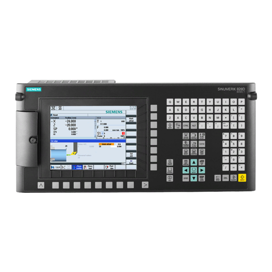
Page 15: Ppu Version 24X.3 Basic
System description 2.2 PPU version 24x.3 BASIC PPU version 24x.3 BASIC Front side of the PPU 24x.3 BASIC Manual, 01/2014, 6FC5397-2DP40-3BA3... - Page 16 System description 2.2 PPU version 24x.3 BASIC ① ⑩ Front cover ② Menu back key ③ Alphabetic key group ④ Control key group ⑤ Hotkey group ⑥ Cursor key group ⑦ Numerical block ⑧ Menu forward key ⑨ 3/8" threads for additional components ⑪...
- Page 17 System description 2.2 PPU version 24x.3 BASIC Rear side of the PPU 24x.3 BASIC ① ② X122, X132 Digital inputs/outputs, drive ③ ④ X242, X252 Digital inputs/outputs for NC; controller of the analog spindle (X252) ⑤ X143 Handwheels ⑥ M, T2, T1, T0 Measuring sockets ⑦...
-
Page 18: Ppu Versions 26X.3 And 28X.3
System description 2.3 PPU versions 26x.3 and 28x.3 PPU versions 26x.3 and 28x.3 Front of the PPU versions 26x.3 and 28x.3 Manual, 01/2014, 6FC5397-2DP40-3BA3... - Page 19 System description 2.3 PPU versions 26x.3 and 28x.3 ① Front cover ② Menu back key ③ Alphabetic key group ④ Control key group ⑤ Hotkey group ⑥ Cursor key group ⑦ Numerical block ⑧ Menu forward key ⑨ 3/8" threads for additional components ⑩...
- Page 20 System description 2.3 PPU versions 26x.3 and 28x.3 Rear of the PPU versions 26x.3 and 28x.3 ① ② X122, X132 Digital inputs/outputs, drive ③ ④ X242, X252 Digital inputs/outputs for NC; controller of the analog spindle (X252) ⑤ X143 Handwheels ⑥...
-
Page 21: Operator Controls And Display Elements
System description 2.4 Operator controls and display elements Operator controls and display elements TFT color display The TFT color display has a diagonal size of 10.4" (PPU 26x.3/28x.3) or 8.4" (PPU 24x.3). The resolution is 800 x 600 pixels. The softkeys are arranged in an 8 + 8 layout; this makes the CNC easy to operate using only a very small number of menu levels. -
Page 22: Type Plate
System description 2.5 Type plate Function corresponds to PC Function corresponds to PC key function key function Home CTRL key Page up ALT key Page down Delete Cursor up Insert Cursor left Enter Cursor right Cursor down 5 (in numeric key group) A ... - Page 23 System description 2.5 Type plate Figure 2-5 Horizontal PPU type plate Figure 2-6 Vertical PPU type plate Note MAC addresses The MAC addresses printed on the type plate of the PPU are required for configuring the PLC I/O Interface communications networks based on PROFINET and Industrial Ethernet. There is a similar situation for the machine control panels and the I/O modules.
-
Page 24: System Overview
System description 2.6 System overview System overview Configuration with four axes (basic configuration) The following configuration shows a typical example with SINAMICS S120 booksize: Figure 2-7 Configuration example 1: Basic configuration with four axes Manual, 01/2014, 6FC5397-2DP40-3BA3... - Page 25 System description 2.6 System overview Configuration with S120 Combi and six axes The following configuration shows the maximum expansion stage with SINAMICS S120 Combi: Figure 2-8 Configuration example 2: Maximum expansion stage with six axes and with Safety Integrated Manual, 01/2014, 6FC5397-2DP40-3BA3...
-
Page 26: Connectable Components
System description 2.7 Connectable components Connectable components Component overview The following components can be connected to the PPU: ● Machine Control Panel MCP 310C PN, MCP 483C PN Contains the keys and switches required for the operation of a machine (turning or milling machine). -
Page 27: Ordering Data
System description 2.8 Ordering data Ordering data Ordering data of the components SINUMERIK 828D is generally marketed in sales packages with drives, motors and accessories. For orders, please contact your local Siemens sales representative. Table 2-1 Components Designation Article number Panel Processing Unit without system software ●... - Page 28 System description 2.8 Ordering data Spare parts Table 2-2 Spare parts Designation Article number Set of tensioners (9 units) 6FC5248-0AF14-0AA0 CompactFlash card (empty), 2 GB 6FC5313-5AG00-0AA2 Front flap with fastening 6FC5348-2AA00-0AA0 Accessories Table 2-3 Accessories Designation Article number SENTRON PAC3200 Power Monitoring Device 7KM2112-0BA00-3AA0 SENTRON PAC4200 Power Monitoring Device 7KM4212-0BA00-3AA0...
-
Page 29: Compactflash Cards
System description 2.9 CompactFlash Cards CompactFlash Cards 2.9.1 CompactFlash card system Overview The PPU has two slots for CompactFlash cards: ● The slot for the user CompactFlash card is located at the front behind the front flap. ● The slot for the system CompactFlash card with the system software is at the rear. CompactFlash card with system software The system CompactFlash card is shipped in a bootable condition. -
Page 30: Inserting The System Compactflash Card
System description 2.9 CompactFlash Cards ● Only use memory cards that have been approved by Siemens for use with SINUMERIK. Even though SINUMERIK follows general industry standards for memory cards, it is possible that memory cards from some manufacturers will not function perfectly in this device or are not completely compatible with it (you can obtain information on compatibility from the memory card manufacturer or supplier). - Page 31 System description 2.9 CompactFlash Cards Figure 2-9 Mounting position Replacing the system CompactFlash card CAUTION Electrostatic Device (ESD) Before you touch a CompactFlash card, discharge yourself at the cabinet or at the ground terminal. The CompactFlash cards may only be inserted or removed when the control unit is disconnected from the power supply.
-
Page 32: Compactflash Card For User Data
System description 2.9 CompactFlash Cards 4. Pull out the CompactFlash card sideways. ③ 5. Gently insert the new CompactFlash card into slot until it clicks into place. ② 6. Re-attach the metal cover by first guiding it in backward, then tilting into the end position ①... - Page 33 System description 2.9 CompactFlash Cards Inserting the CompactFlash card To correctly insert the CompactFlash card in the slot, note the position the edge (arrow) in the figure below: Figure 2-10 Direction to insert the user CompactFlash card Manual, 01/2014, 6FC5397-2DP40-3BA3...
-
Page 35: Application Planning
Application planning Secondary electrical conditions 3.1.1 Protective Separation as per EN 61800-5-1 Protective separation of the interfaces Note By using an extra-low voltage, all interfaces have protective separation according to Class DVC A (SELV/PELV). 3.1.2 Grounding concept Components The SINUMERIK 828D system consists of a number of individual components which have been designed so that the system complies with the appropriate EMC and safety standards. - Page 36 Application planning 3.1 Secondary electrical conditions Shielded signal cable with reference ground Motor Encoder Equipotential bonding conductor Protective connection (via metal design or green-yellow protective conductors) Figure 3-1 Grounding concept The following rules apply for external cable cross sections: ● PA cross-section ≥ 10 mm ●...
-
Page 37: Ri Suppression Measures
However, if the system cannot operate without them, then the cable shields must be connected at both ends. Furthermore, the non-Siemens device must be connected to the controller via an equipotential bonding cable. Cable definitions The following cables are permissible: ●... - Page 38 Application planning 3.1 Secondary electrical conditions ● If signal lines cannot be routed a sufficient distance away from other cables, they must be installed in grounded cable ducts (metal). ● The clearance (interference injection area) between the following lines must be kept to a minimum: –...
-
Page 39: Climatic And Mechanical Environmental Conditions
Application planning 3.2 Climatic and mechanical environmental conditions Climatic and mechanical environmental conditions 3.2.1 Ambient conditions Observing the ambient conditions The controller is tested for compliance with the ambient conditions specified below. Fault-free operation is only ensured if: ● These ambient conditions are maintained when storing, transporting and operating the equipment. -
Page 40: Operating Conditions
Application planning 3.2 Climatic and mechanical environmental conditions Relative humidity 5 ... 95% 10 ... 100% Permissible change in max. 0.1% / min (≙ 6% / h) relative humidity Averaged over 5 min Assuming a direct change in the specified air temperatures 3.2.3 Operating Conditions Note... -
Page 41: Recycling And Disposal
The user must consider interference radiation for the complete system. Particular attention should be paid to cabling. Please contact your sales representative for assistance and support. If compliance with limit value class C2 is required, please contact your local Siemens sales partner. Note Please see the relevant SINAMICS documentation for EMC notes on how to deal with line filters and reactors. -
Page 43: Installing
Installing Installation notes PPU modules may only be installed in housings, cabinets or in isolated electrical business establishments. Housings, cabinets, or isolated electrical business establishments may only be accessed by trained or authorized personnel. DANGER Risk of electric shock The entire system must be voltage-free when mounting or wiring the SINUMERIK 828D. Components in the control cabinet The SINAMICS components and the axis expansion modules are installed in a control cabinet. - Page 44 Installing 4.1 Mounting positions Installation of the horizontal PPU variant ① Mounting frame Figure 4-1 Clearance for ventilation and cables in the horizontal PPU Manual, 01/2014, 6FC5397-2DP40-3BA3...
- Page 45 Installing 4.1 Mounting positions Panel cutout of the horizontal PPU variant ① Mounting frame ② Seal area ③ Pressure point for tensioners Figure 4-2 Horizontal PPU panel cutout Manual, 01/2014, 6FC5397-2DP40-3BA3...
- Page 46 Installing 4.1 Mounting positions ① Mounting frame ② Tensioner (10 parts) ③ Seal ④ Shield contact ⑤ Grounding screw M5 ⑥ Interfaces Figure 4-3 Horizontal PPU mounting Manual, 01/2014, 6FC5397-2DP40-3BA3...
- Page 47 Installing 4.1 Mounting positions Installation of the vertical PPU variant ① Mounting frame Figure 4-4 Clearance for ventilation and cables in the vertical PPU Manual, 01/2014, 6FC5397-2DP40-3BA3...
- Page 48 Installing 4.1 Mounting positions Panel cutout of the vertical PPU variant ① Mounting frame ② Pressure point for tensioners ③ Seal area Figure 4-5 Vertical PPU panel cutout Manual, 01/2014, 6FC5397-2DP40-3BA3...
- Page 49 Installing 4.1 Mounting positions ① Mounting frame ② Tensioner (10 parts) ③ Seal ④ Shield contact ⑤ Grounding screw M5 ⑥ Interfaces Figure 4-6 Installation of the vertical PPU variant Manual, 01/2014, 6FC5397-2DP40-3BA3...
-
Page 50: Dimension Drawings
Installing 4.2 Dimension drawings Dimension drawings PPU horizontal Figure 4-7 Horizontal PPU dimensioning Manual, 01/2014, 6FC5397-2DP40-3BA3... - Page 51 Installing 4.2 Dimension drawings PPU vertical Figure 4-8 Vertical PPU dimensioning Manual, 01/2014, 6FC5397-2DP40-3BA3...
-
Page 53: Rules For Permitted Topologies
Rules for permitted topologies Topology rules for S120 Combi Topology rules for DRIVE-CLiQ There are fixed DRIVE-CLiQ topology rules for the S120 Combi. These rules must be observed. If these rules are violated, then a corresponding alarm is displayed. Assigning the DRIVE-CLiQ interfaces Table 5-1 Assigning the DRIVE-CLiQ interfaces on the S120 Combi DRIVE-CLiQ interface... -
Page 54: Topology Rules For S120 Booksize
Rules for permitted topologies 5.2 Topology rules for S120 Booksize DRIVE-CLiQ interface Connection with X201 Remains empty X202 Motor encoder for feedrate 2nd expansion axis (via Sensor Module) Double Motor Module X200 X101 of the PPU X201 Remains empty X202 Motor encoder for feedrate 1st expansion axis X203 Motor encoder for feedrate 2nd expansion axis... - Page 55 Rules for permitted topologies 5.2 Topology rules for S120 Booksize ● The computing power of the respective Control Unit ● The set processing and communication cycles In addition to the binding wiring rules that must be observed, some additional recommendations as well as topology examples for DRIVE-CLiQ wiring are provided in the PPU manual.
- Page 56 Rules for permitted topologies 5.2 Topology rules for S120 Booksize ● The following applies to the booksize format: – In the servo control and vector U/f control operating modes, only one Line Module may be connected to the Control Unit. In the vector control operating mode, a maximum of three further Line Modules may be connected in parallel (i.e.
- Page 57 Rules for permitted topologies 5.2 Topology rules for S120 Booksize ● The sampling times (p0115[0] and p4099) of all components that are connected to a DRIVE- CLiQ line must be divisible by one another with an integer result. If the current controller sampling time on a DO has to be changed to another pattern that does not match the other DOs on the DRIVE-CLiQ line, the following options are available: –...
-
Page 58: Topology Rules For Safety Integrated Functions
Rules for permitted topologies 5.3 Topology rules for Safety Integrated functions Note If an additional encoder is connected to a Motor Module, it is assigned to this drive as encoder 2 in the automatic configuration. At a Double Motor Module, an encoder at X201 is assigned to the 2nd feedrate as 2nd measuring system. -
Page 59: Topology Example Without Safety Integrated Functions
Rules for permitted topologies 5.4 Topology example without Safety Integrated functions Number Port 1 at the PPU Port 2 at the PPU Port 3 at the PPU Example in the figure: of axes X100 X101 X102 1 x LM 1 x TM54F 1 x NX10.3 Topology with SINAMICS 4 x MoMo... - Page 60 Rules for permitted topologies 5.4 Topology example without Safety Integrated functions Topology for the maximum configuration with SINAMICS S120 booksize and six axes Figure 5-4 DRIVE-CLiQ wiring without NX Manual, 01/2014, 6FC5397-2DP40-3BA3...
- Page 61 Rules for permitted topologies 5.4 Topology example without Safety Integrated functions Topology for the maximum configuration with SINAMICS S120 booksize and eight axes Figure 5-5 DRIVE-CLiQ wiring with NX Manual, 01/2014, 6FC5397-2DP40-3BA3...
- Page 62 Rules for permitted topologies 5.4 Topology example without Safety Integrated functions Topology with SINAMICS S120 chassis and SINAMICS S120 booksize and eight axes Figure 5-6 DRIVE-CLiQ wiring with NX Manual, 01/2014, 6FC5397-2DP40-3BA3...
-
Page 63: Topology Example With Safety Integrated Functions
Rules for permitted topologies 5.5 Topology example with Safety Integrated functions Topology example with Safety Integrated functions Note Additional notes on Safety Integrated functions are available under: SINAMICS S120 Safety Integrated Function Manual. Topology with SINAMICS S120 booksize and six plus two axes Figure 5-7 DRIVE-CLiQ wiring with Safety Integrated functions and NX Manual, 01/2014, 6FC5397-2DP40-3BA3... - Page 64 Rules for permitted topologies 5.5 Topology example with Safety Integrated functions Topology with SINAMICS S120 booksize and five plus three axes Figure 5-8 DRIVE-CLiQ wiring with Safety Integrated functions and NX Note Please note the following conditions for the examples below: 1.
- Page 65 Rules for permitted topologies 5.5 Topology example with Safety Integrated functions Topology with SINAMICS S120 chassis and SINAMICS S120 booksize and six axes Figure 5-9 DRIVE-CLiQ wiring with Safety Integrated functions and without NX Manual, 01/2014, 6FC5397-2DP40-3BA3...
- Page 66 Rules for permitted topologies 5.5 Topology example with Safety Integrated functions Topology with SINAMICS S120 chassis and SINAMICS S120 booksize and eight axes Figure 5-10 Example with Safety Integrated functions and with NX Note You can find an example with SINAMICS S120 Combi and Safety Integrated functions under Controller features (Page 13) or in the SINAMICS S120 Combi Manual.
-
Page 67: Interface Description
Interface description Interface overview Requirement DANGER Risk of electric shock The entire system must be voltage-free when mounting or wiring the SINUMERIK 828D. Manual, 01/2014, 6FC5397-2DP40-3BA3... - Page 68 Interface description 6.1 Interface overview Connection options The overview below shows the interfaces and their connection possibilities: Terminal Module SINUMERIK 828D Article number TM54F PPU 240.3/PPU 241.3 Pre-assembled cable PPU 260.3/PPU 261.3 PPU 280.3/PPU 281.3 SINAMICS S120 DRIVE-CLiQ cable X100 see MOTION-CONNECT (see Catalog NC 61) DRIVE-CLiQ X101...
-
Page 69: Power Supply Connection
Interface description 6.2 Power supply connection Note If your axis grouping contains a Smart Line Module without DRIVE-CLiQ (5 kW or 10 kW), you must assign the Smart Line Module enabling signal to the X122.1 digital input on the PPU. Definition The abbreviations used in "Signal type"... - Page 70 Interface description 6.2 Power supply connection Table 6-2 Input voltage specification Parameter Values Typ. power consumption 1.2 A Max. power consumption 2.5 A Max. starting current 4.4 A PPU only (processor, memory, etc.) PPU with full load (USB, handwheels) DANGER Risk of lightning strike In the case of supply lines >...
-
Page 71: Connecting The Power Supply
Interface description 6.3 Ethernet 6.2.2 Connecting the power supply Cable specification DANGER Protective separation The 24 V direct voltage must be configured as an extra-low-voltage with protective separation - DVC A or PELV. The required 24 VDC load power supply is wired to the screw-type terminal block (X1). Use flexible cables with a cross-section of 0.25 to 2.5 mm (or AWG 23 to AWG 13) for wiring the power supply according to the maximum occurring current. - Page 72 Interface description 6.3 Ethernet The interfaces are designed for operation in full-duplex mode; in other words, the ports can be used for the sending as well as for the receiving of data packets. The ports are connected as an Ethernet terminal with 10/100 Mbit: ●...
-
Page 73: Plc I/O Interface Based On Profinet
Interface description 6.4 PLC I/O Interface based on PROFINET PLC I/O Interface based on PROFINET Pin assignment PN1, PN2 Signal name Signal type Meaning Transmit data + Transmit data - Receive data + N.C. Not assigned N.C. Not assigned Receive data - N.C. - Page 74 Interface description 6.4 PLC I/O Interface based on PROFINET LED displays on the rear For diagnostic purposes, the RJ45 sockets are each equipped with a green and a yellow LED. This allows the following information on the respective port to be displayed: Name Color Status...
-
Page 75: Addressing The I/O Modules
Interface description 6.4 PLC I/O Interface based on PROFINET Name Color Status Meaning Lights up NC in stop mode: ● When booting, if NC Ready is not yet available ● Critical fault (power off/on necessary) Yellow Cyclic flashing NC operation Yellow Lights up Accessing the CompactFlash card. -
Page 76: Digital Inputs/Outputs
Interface description 6.5 Digital inputs/outputs I/O module Device name IP address Input addresses Output addresses PN/PN coupler * pn-pn-coupler20 96 … 111 96 … 111 External machine control panel mcp-pn64 112 … 125 112 … 121 Reserved 126 … 131 122 ... - Page 77 Interface description 6.5 Digital inputs/outputs Signal name Meaning MEXT2 Ground for pins 1...6 P24EXT1 +24 V power supply IO12 DI/DO12 Digital input/output 12 IO13 DI/DO13 Digital input/output 13 MEXT1 Ground for pins 9, 10, 12, 13 IO14 DI/DO14 Digital input/output 14 IO15 DI/DO15 Digital input/output 15...
- Page 78 Interface description 6.5 Digital inputs/outputs X242 pin assignment Signal name NC variable Meaning Not connected Not connected DIN1 $A_IN[1] Digital NC input 1 DIN2 $A_IN[2] Digital NC input 2 DIN3 $A_IN[3] Digital NC input 3 DIN4 $A_IN[4] Digital NC input 4 MEXT4 Ground for pins 3...6 P24EXT3...
- Page 79 Interface description 6.5 Digital inputs/outputs Signal name NC variable Meaning DOUT12 ● Without analog spindle: Digital NC output 12 ● With analog spindle: Travel direction of the analog spindle (in accordance with MD30134 $MA_IS_UNIPOLAR_OUT PUT) MEXT3 Ground for pins 9, 10, 12, 13 The following assignment applies to the terminals: ●...
- Page 80 Interface description 6.5 Digital inputs/outputs 3. Wire the digital outputs of the interface for connection of the actuators. 4. Insert the cable into the corresponding screw terminal. References More information about digital inputs/outputs can be found in: Basic Functions Function Manual, "PLC for SINUMERIK 828D" (P4) Manual, 01/2014, 6FC5397-2DP40-3BA3...
-
Page 81: Terminal Connection Diagram
Interface description 6.5 Digital inputs/outputs 6.5.1 Terminal connection diagram The following figure shows the terminal connection diagram for the digital inputs/outputs of a PPU. Figure 6-4 Terminal connection diagram for digital inputs/outputs Manual, 01/2014, 6FC5397-2DP40-3BA3... -
Page 82: Example: Connecting An Inductive Proximity Switch (Beros)
Interface description 6.5 Digital inputs/outputs 6.5.2 Example: Connecting an inductive proximity switch (BEROs) Boundary conditions When connecting a BERO the following rules must be observed: ● BEROs can always be connected to each input. ● Because both the DI input terminals as well as the parameterizable DI/DO terminals are isolated, the ground of the supply must be connected to the associated M terminal. -
Page 83: Technical Data
Interface description 6.5 Digital inputs/outputs 6.5.3 Technical data Note An open input is interpreted as "low". Note Terminals MEXT1 ... MEXT4 must be connected for the digital inputs/outputs to function. This can be done as follows: ● Connect the ground reference of the digital inputs. ●... -
Page 84: Drive-Cliq
Interface description 6.6 DRIVE-CLiQ Parameter Value As output: Voltage 18 V to 30 V Load current per output, maximum 0.5 A Load current per connector, maximum Signal propagation times L → H: 50 μs H → L: 200 μs Galvanic isolation Yes: The reference potential is terminal1M/1P24 (24 V Digital outputs Table 6-8... - Page 85 Interface description 6.6 DRIVE-CLiQ DRIVE-CLiQ interfaces are used to connect SINAMICS S120 components to the PPU. The following rules apply: ● Topology rules for S120 Combi (Page 53) ● Topology rules for S120 Booksize (Page 54) ● Topology rules for Safety Integrated functions (Page 58) ●...
-
Page 86: Sinamics Components
Interface description 6.6 DRIVE-CLiQ 6.6.2 SINAMICS components Components with DRIVE-CLiQ As a rule, all SINAMICS components approved for SINUMERIK 828D can be connected using DRIVE-CLiQ. Component Description NX10.3 Axis expansion module Active / Basic / Smart Line Line Modules provide the central power supply to the DC link. Modules Booksize / Chassis Single / Double Motor Modules Motor Modules draw their power from the DC link to supply the... -
Page 87: Handwheel
Interface description 6.7 Handwheel Handwheel Pin assignment Table 6-9 X143 pin assignment Signal name Meaning 5 VDC power supply Ground Handwheel pulses track A, channel 1 Handwheel pulses track A (negated), channel 1 Handwheel pulses track B, channel 1 Handwheel pulses track B (negated), channel 1 5 VDC power supply Ground Handwheel pulses track A, channel 2... - Page 88 Interface description 6.7 Handwheel Connection diagram Possible connection types for handwheels are shown in the following diagram. Figure 6-6 Connecting a handwheel with different data transfer types Max. two electronic handwheels can be connected to connector X143 on the rear of the PPU. The handwheel must meet the following requirements: Manual, 01/2014, 6FC5397-2DP40-3BA3...
-
Page 89: Usb
Interface description 6.8 USB ● Transmission procedure: Differential or non-symmetrical signal transfer ● Signals: – Differential signal transfer (RS422): For each track a signal and a negated signal – Non-symmetrical signal transfer: For each track, a 5 V TTL signal ●... -
Page 90: Rs 232 Serial Interface
Interface description 6.9 RS 232 serial interface Cable specification Features Variants Connector type: USB socket - type A Version: USB 2.0 Current carrying capacity: 0.5 A per connector Max. data transmission rate 12 Mbit/s Max. cable length Note The 5 V power supply is designed to be short-circuit proof. RS 232 serial interface Pin assignment Table 6-11... - Page 91 Interface description 6.9 RS 232 serial interface Feature Version Article number 6FX8002-1AA11-1□□0 Max. cable length Manual, 01/2014, 6FC5397-2DP40-3BA3...
-
Page 93: Connectable Components
Connectable components MCP 483C PN Description The MCP 483C PN machine control panel enables user-friendly operation of the machine functions. It can be used with a SINUMERIK 828D control for machine-level operation of milling and turning machines. All keys are designed with replaceable caps for machine-specific adaptations. The key caps can be freely inscribed using laser. -
Page 94: Operator Controls And Display Elements
Connectable components 7.1 MCP 483C PN 7.1.1 Operator controls and display elements Operator controls (front) ① Emergency-Stop button ② Installation locations for control devices (d = 16 mm) ③ Reset button ④ Program control ⑤ Operating modes, machine functions ⑥ User keys T1 to T15 ⑦... - Page 95 Connectable components 7.1 MCP 483C PN Emergency Stop circuit Figure 7-2 Emergency Stop circuit EMERGENCY STOP Press the red Emergency-Stop button in emergencies when ● people are at risk. ● there is the danger of a machine or workpiece being damaged. As a rule, when operating the Emergency-Stop button, all drives are brought to a standstill with max.
- Page 96 Connectable components 7.1 MCP 483C PN Display elements (rear) ① ④ Ground terminal Detail for ② Feed override X30 ③ Spindle override X31 ④ PLC I/O Interface X20/X21 connections ⑤ Slot for emergency stop ⑥ Installation locations for additional control devices (d = 16 mm) ⑦...
-
Page 97: Mounting
Connectable components 7.1 MCP 483C PN Name Designation Color Description Flashes 0.5 Hz: System software running, RUN state PNFault Not lit: Module is operating without errors; data exchange with all configured IO devices is running. Lit: Serious bus fault; only output when one of the following errors is detected for the ports: ●... -
Page 98: Connecting
Connectable components 7.1 MCP 483C PN Figure 7-4 Panel cutout of MCP 483C PN MCP 483C PN dimension drawing Figure 7-5 MCP 483C PN dimensions 7.1.3 Connecting Securing the cables Two equivalent connections (Fast Ethernet) are available for establishing the PLC I/O Interface communication network based on PROFINET. - Page 99 Connectable components 7.1 MCP 483C PN The Ethernet cables are not included in the scope of delivery. When connecting the machine control panel to the SINUMERIK 828D, please use the preassembled SINAMICS DRIVE-CLiQ signal cables; from a technical point of view, these are also suitable for use with PROFINET. NOTICE Damage to cables Make sure that all cables are routed so that they do not come into contact with chafing edges.
- Page 100 Connectable components 7.1 MCP 483C PN Table 7-1 Assignment of connectors X20, X21 Signal name Signal type Meaning Transmit + Transmit - Receive + N.C. Not assigned N.C. Not assigned Receive - N.C. Not assigned N.C. Not assigned Rotary switch: Feed override X30 / spindle override X31 Connector designation: X30/X31 Connector type: 2 x 5-pin plug connector, according to EN 60603-13 with coding Table 7-2...
- Page 101 Connectable components 7.1 MCP 483C PN Optional customer buttons IN (X51 / X52 / X55) Only switches (passive inputs) may be connected via the X51, X52 and X55 connectors. X51 and X52 are typically used for connecting illuminated pushbuttons. The lamps in the buttons are activated via X53 and X54.
- Page 102 Connectable components 7.1 MCP 483C PN Optional customer buttons OUT (X53 / X54) The short-circuit-proof outputs X53/X54 are provided to control lamps in the buttons. Lamps with 24 V and 1.2 W per output are recommended. Figure 7-7 Main circuit diagram for input circuit for X53 and X54 CAUTION Do not connect any relays, valves or other inductive loads.
- Page 103 Connectable components 7.1 MCP 483C PN X60 handwheel Via X60, you can connect 1 handwheel either with TTL or difference signals. Note The handwheel is supplied by the MCP module with 5 V / 100 mA. An external power supply is not permitted.
-
Page 104: Parameterization
Connectable components 7.1 MCP 483C PN Switch S2 Switch position: "ON" is at the top. Table 7-9 Switch S2 is set as delivered Meaning PLC I/O Interface PROFINET address "0" The two switches S2-9 and S2-10 must remain set to "ON". The switches S2-1 to S2-8 define the PROFINET address. - Page 105 Connectable components 7.1 MCP 483C PN Byte Bit7 Bit6 Bit5 Bit4 Bit3 Bit2 Bit1 Bit0 EB115 Keyswitch Feedrate override Single E (2 D (2 C (2 B (2 A (2 RESET position 1 block EB116 Direction keys Keyswitch Axis selection Rapid 4.
- Page 106 Connectable components 7.1 MCP 483C PN Output image Table 7-13 Output image MCP 483C PN Byte Bit7 Bit6 Bit5 Bit4 Bit3 Bit2 Bit1 Bit0 AB112 Machine function Operating mode 1000 INC 100 INC 10 INC 1 INC TEACH IN AUTO AB113 Machine function Feed...
-
Page 107: Technical Data
Connectable components 7.1 MCP 483C PN Assignment of the inputs (I) and outputs (O) to the keys and LEDs Figure 7-9 Inputs and outputs of the MCP 483C PN keyboard 7.1.5 Technical data MCP 483C PN Parameter Value Input voltage 24 V DC Power consumption, max. -
Page 108: Spare Parts And Accessories
Connectable components 7.1 MCP 483C PN Parameter Value Temperature limits: ● Storage in acc. with EN 60721-3-1 -25 °C ... 55 °C ● Transportation (in transportation packaging) -25 °C ... 55 ºC in acc. with EN 60721-3-2 0 ... 45 ºC (front) ●... - Page 109 Connectable components 7.1 MCP 483C PN Name Description Article number ntity Rotary switch for Override feedrate / rapid traverse electronic 6FC5247–0AF13–1AA0 feed rotary switch 1x23G, T=32, cap, knob, pointer, feedrate and rapid-traverse dials Set of tensioners Set of tensioners for supplementary operator 6FC5248–0AF14–0AA0 components with 2.5 mm profile, 20mm length Table 7-15...
- Page 110 Connectable components 7.1 MCP 483C PN 5. Remove the connector at the end of the rotary switch cable from the socket. 6. Remove the rotary switch. ① Nut of the collet ② Rotary knob ③ ④ Rotary switch shaft ⑤ Fastening nut ⑥...
-
Page 111: Mcp 310C Pn
Connectable components 7.2 MCP 310C PN ② 8. Place the cover on the rotary knob and snap it into position. ⑦ 9. Fold and fasten the connecting cable as shown in the figure on the right. ① O-ring Detail diagram of the connector ②... - Page 112 Connectable components 7.2 MCP 310C PN The machine control panel is mounted from the rear with special tension jacks supplied with the panel. Operator controls ● Operating mode and function keys: – 49 keys with assigned LEDs – Direction keys for milling machines with rapid traverse override (key covers for direction keys for turning machines are supplied) –...
-
Page 113: Operator Controls And Display Elements
Connectable components 7.2 MCP 310C PN 7.2.1 Operator controls and display elements Operator controls ① Operating modes and machine functions ② 16 customer keys ③ Spindle control ④ Slot for EMERGENCY STOP button or override switch for the spindle control ⑤... - Page 114 Connectable components 7.2 MCP 310C PN Mounting slots for control devices WARNING Warning of damage ⑥ Do not chip out the openings for mounting control devices ; drill them to the required width. Key caps All keys of the MCP 310C PN come with changeable key caps. Refer to the following table for the additional replacement key caps provided for lathes in the accessories pack: Key cap Symbol number...
- Page 115 Connectable components 7.2 MCP 310C PN ① Slot for Emergency-Stop button or spindle override ② Power supply interface X10 ③ X60 connection for handwheel, X61 reserved ④ Switch for setting the handwheel signal type ⑤ Switch S2 ⑥ LEDs ⑦ Ethernet cable strain relief ⑧...
-
Page 116: Mounting
Connectable components 7.2 MCP 310C PN LEDs for status display Table 7-17 LEDs Name Designation Color Description PowerOK Green Lit: Power supply ok PNSync Green Lit: System software running, STOP state Flashes 0.5 Hz: System software running, RUN state PNFault Not lit: Module is operating without errors;... - Page 117 Connectable components 7.2 MCP 310C PN Tension jacks The machine control panel is attached using 6 tension jacks (tightening torque, 0.5 Nm). Figure 7-14 Panel cut-out for the machine control panel MCP 310C PN Dimension drawing ① In the sealing area ②...
-
Page 118: Connecting
Connectable components 7.2 MCP 310C PN 7.2.3 Connecting Securing the cables Two equivalent connections (Fast Ethernet) are available for establishing the PLC I/O Interface communication network based on PROFINET. Two cable ties are included in the scope of delivery. You use these to secure the Ethernet cables on the cover plate at the rear of the machine control panel. - Page 119 Connectable components 7.2 MCP 310C PN Signal name Signal type Meaning 24 V potential 24 V ground SHIELD Shield connection PLC I/O Interface pin assignment Connector designation: X20, X21 Connector type: RJ45 socket Table 7-18 Assignment of connectors X20, X21 Signal name Signal type Meaning...
- Page 120 Connectable components 7.2 MCP 310C PN Optional customer buttons IN (X51 / X52 / X55) Only switches (passive inputs) may be connected via the X51, X52 and X55 connectors. X51 and X52 are typically used for connecting illuminated pushbuttons. The lamps in the buttons are activated via X53 and X54.
- Page 121 Connectable components 7.2 MCP 310C PN Optional customer buttons OUT (X53 / X54) The short-circuit-proof outputs X53/X54 are provided to control lamps in the buttons. Lamps with 24 V and 1.2 W per output are recommended. Figure 7-17 Main circuit diagram for input circuit for X53 and X54 CAUTION Do not connect any relays, valves or other inductive loads.
- Page 122 Connectable components 7.2 MCP 310C PN X60 handwheel Via X60, you can connect 1 handwheel either with TTL or difference signals. Note The handwheel is supplied by the MCP module with 5 V / 100 mA. An external power supply is not permitted.
-
Page 123: Parameterization
Connectable components 7.2 MCP 310C PN Switch S2 Switch position: "ON" is at the top. Table 7-26 Switch S2 is set as delivered Meaning PLC I/O Interface PROFINET address "0" The two switches S2-9 and S2-10 must remain set to "ON". The switches S2-1 to S2-8 define the PROFINET address. - Page 124 Connectable components 7.2 MCP 310C PN Byte Bit7 Bit6 Bit5 Bit4 Bit3 Bit2 Bit1 Bit0 EB115 Keyswitch Keyswitch Feedrate override E (2 D (2 C (2 B (2 A (2 RESET position 2 position 1 EB116 Direction keys Rapid traverse EB117 EB118 Unassigned customer keys...
- Page 125 Connectable components 7.2 MCP 310C PN Output image Table 7-30 Output image MCP 310C PN Byte Bit7 Bit6 Bit5 Bit4 Bit3 Bit2 Bit1 Bit0 AB112 * NC Spindle Single Stop Spindle - 100% Spindle + block AUTO AB113 Spindle * Spindle Spindle RESET Teach...
-
Page 126: Technical Data
Connectable components 7.2 MCP 310C PN Assignment of the inputs (I) and outputs (O) to the keys and LEDs Figure 7-19 Inputs and outputs of the MCP 310C PN keyboard 7.2.5 Technical data MCP 310C PN Parameter Value Input voltage 24 V DC Power consumption, max. -
Page 127: Spare Parts And Accessories
Connectable components 7.2 MCP 310C PN Parameter Value Temperature limits: ● Operation in acc. with EN 60721-3-3 0 ... 45 ºC (front) 0 to 55 °C (rear) ● Storage in acc. with EN 60721-3-1 -25 °C ... 55 °C ● Transportation (in transportation packaging) in acc. - Page 128 Connectable components 7.2 MCP 310C PN Name Description Amoun Article number Override Spindle/rapid traverse override, electronic 6FC5247–0AF12–1AA0 rotary switch 1x16G, T=24, cap, knob, Spindle rotary pointer, spindle and rapid-traverse dials switch Override Override feedrate / rapid traverse electronic 6FC5247–0AF13–1AA0 rotary switch 1x23G, T=32, cap, knob, Feed rotary switch pointer, feedrate and rapid-traverse dials Key cap...
- Page 129 Connectable components 7.2 MCP 310C PN 5. Remove the connector at the end of the rotary switch cable from the socket. 6. Remove the rotary switch. ① Nut of the collet ② Rotary knob ③ ④ Rotary switch shaft ⑤ Fastening nut ⑥...
-
Page 130: Mcp Interface Pn
Connectable components 7.3 MCP Interface PN ② 8. Place the cover on the rotary knob and snap it into position. ⑦ 9. Fold and fasten the connecting cable as shown in the figure on the right. ① O-ring Detail diagram of the connector ②... - Page 131 Connectable components 7.3 MCP Interface PN You can connect the following operator controls to the interface: ● 80 single keys ● 64 LEDs ● Handwheel ● 2 override switches The following inputs/outputs are also available: ● 9 digital inputs (5 V) ●...
- Page 132 Connectable components 7.3 MCP Interface PN Display ① Type plate ② Terminal strips / connectors for operator controls ③ Diagnostic LEDs ④ PROFINET interface X2 (Industrial Ethernet 100 Mbit/s) ⑤ PROFINET interface X3 (Industrial Ethernet 100 Mbit/s) ⑥ Grounding screw M5 for potential equalization connection ⑦...
-
Page 133: Mounting
Connectable components 7.3 MCP Interface PN Name Function Status Meaning H501 BUS_SYNC Does not light No PROFINET communication. Lights up PROFINET is synchronized (STOP state). Flashes (0.5 PROFINET is synchronized (RUN state). H502 BUS_FAULT Lights up PROFINET group fault. H505 Temperature alarm (red) Lights up At least one temperature limit is being exceeded. -
Page 134: Connection
Connectable components 7.3 MCP Interface PN 7.3.2 Connection Position of the interfaces Figure 7-24 MCP Interface PN interfaces Interface overview 24 VDC power supply PROFINET interface PROFINET interface Interface for rotary switch feed override Interface for rotary switch spindle override X40/X41 Digital inputs (24 V) X51 / X52 / X55... - Page 135 Connectable components 7.3 MCP Interface PN Rotary switch: Feed override X30 / spindle override X31 Connector designation: X30/X31 Connector type: 2 x 5-pin plug connector, according to EN 60603-13 with coding Table 7-31 Assignment of connector X30 / X31 Signal name Signal type Meaning N.C.
- Page 136 Connectable components 7.3 MCP Interface PN Signal name Type Meaning DI125.4 24 V input 2 Ground Table 7-33 X41 pin assignments Signal name Type Meaning DI125.5 24 V input 3 DI125.6 24 V input 4 DI125.7 24 V input 5 Ground Table 7-34 Technical data for X40, X41...
- Page 137 Connectable components 7.3 MCP Interface PN Figure 7-26 Block diagram X51, X52, X55 Connector designation: X51, X52, X55 Connector type: 4-pin plug connector Special feature: No galvanic isolation Max. cable length: 0.6 m Table 7-35 Assignment of connector X51 Signal name Type Meaning DI124.0...
- Page 138 Connectable components 7.3 MCP Interface PN Table 7-38 Technical data for X51, X52, X55 Parameter Value Voltage: Nominal: 0 V to 5 V Permissible: -3 V to 30 V Typical current consumption: 0.2 mA at 5 VDC -0.3 mA at 0 VDC Signal level (including ripple): High signal level: 2.3 V to 5 V Low signal level: 0 V to 1 V...
- Page 139 Connectable components 7.3 MCP Interface PN Table 7-39 Assignment of connector X53 Signal name Type Meaning DO120.3 24 V output 3 (group 1) DO120.4 24 V output 4 (group 1) DO120.5 24 V output 5 (group 1) Ground Table 7-40 Assignment of connector X54 Signal name Type...
- Page 140 Connectable components 7.3 MCP Interface PN Parameter Value Per output at 100% simultaneity of all 15 outputs: 0.15 A UL certified rating Each output: 24 V / 0.15 A general, resistive load 24 V / 3.6 W lamp load 24 V / 0.15 A coil load Handwheel X60 / X62 Via X60, you can connect 1 handwheel either with TTL or difference signals.
- Page 141 Connectable components 7.3 MCP Interface PN Signal name Type Meaning N.C. Not assigned N.C. Not assigned Connector designation: Connector type: 12-pin plug connector Special feature: No galvanic isolation Max. cable length: Table 7-46 Assignment of connector X62 Signal name Type Meaning P5HW 5 V power supply...
- Page 142 Connectable components 7.3 MCP Interface PN Figure 7-28 Schematic circuit diagram X111 Note LED brightness The setting of the LED brightness can be implemented by an additional external resistor connected in series. Connector designation: X111, X112, X113, X114 Connector type: 40-pin plug connector Special feature: No galvanic isolation, with interlock...
- Page 143 Connectable components 7.3 MCP Interface PN Signal name Type Signal name Type DI113.7 DO113.7 DI120.0 DI120.1 DI120.2 DI120.3 Reserved Reserved Table 7-48 Assignment of connector X112 Signal name Type Signal name Type Ground Ground DI114.0 DO114.0 DI114.1 DO114.1 DI114.2 DO114.2 DI114.3 DO114.3 DI114.4...
- Page 144 Connectable components 7.3 MCP Interface PN Signal name Type Signal name Type DI117.3 DO117.3 DI117.4 DO117.4 DI117.5 DO117.5 DI117.6 DO117.6 DI117.7 DO117.7 DI121.0 DI121.1 DI121.2 DI121.3 Reserved Reserved Table 7-50 Assignment of connector X114 Signal name Type Signal name Type Ground Ground DI118.0...
- Page 145 Connectable components 7.3 MCP Interface PN Table 7-52 Technical data of the outputs of X111 to X114 Parameter Value Voltage: 0 V to 5 V (depending on the load) Typical load current (without external 8 mA at LED flow voltage = 2.3 V series resistor): 15 mA at short-circuit Switch S1, S2...
-
Page 146: Parameter Assignment
Connectable components 7.3 MCP Interface PN 7.3.3 Parameter assignment The specifications for assigning input and output bytes listed in the tables are set as standard addresses in the PLC by setting the following machine data: MD12986 PLC_DEACT_IMAGE_LADDR_IN[6] = -1 Standard input image Table 7-56 MCP Interface PN input image Byte... - Page 147 Connectable components 7.3 MCP Interface PN Temperature in °C Representation in byte EB126 0xFF 0xFB Input image of the handwheels Table 7-58 Input image for handwheel data Byte Bit7 Bit6 Bit5 Bit4 Bit3 Bit2 Bit1 Bit0 EB m + 0 Handwheel 1 counter status (16-bit signed, low-order byte equals byte m + 0) EB m + 1...
-
Page 148: Technical Data
Connectable components 7.4 Electronic handwheel 7.3.4 Technical data MCP Interface PN Parameter Value Input voltage 24 VDC Power consumption, max. ● Board 2.4 W ● Handwheels 2 x 0.9 W ● Lamps 54 W (15 x 3.6 W) ● LEDs 4 W (80 x 0.05 W) ●... - Page 149 Connectable components 7.4 Electronic handwheel makes for an extremely precise incremental process. The axis selected via the control can be positioned so that the axes are parallel. The portable handwheel offers a PPR count of 100 S/ ① Handwheel ② Spiral connection cable ③...
- Page 150 Connectable components 7.4 Electronic handwheel Manual, 01/2014, 6FC5397-2DP40-3BA3...
-
Page 151: Mounting
Connectable components 7.4 Electronic handwheel 7.4.2 Mounting Dimensions of the electronic handheld handwheel Figure 7-30 Front view and side view Additional options Optionally, the handheld electronic handwheel can be stored in a screw-on holder. The holder is mounted using three M4 screws (included in the scope of delivery). See also: Mini handheld unit, Chapter "Mounting (Page 157)"... -
Page 152: Connection
Connectable components 7.4 Electronic handwheel 7.4.3 Connection Electrical connection diagram The handheld handwheel is connected via a flange socket using the spiral connection cable. You will find article numbers for the recommended flange socket in Chapter Spare parts and accessories (Page 154). Note If a connected handwheel triggers pulses while in the idle position or when there is only minimal contact, connect it the opposite way round to what is stated on the label. -
Page 153: Technical Specifications
Connectable components 7.4 Electronic handwheel 7.4.4 Technical specifications Handheld electronic handwheel Parameter Value Operating voltage 5 VDC ± 5% Current consumption Max. 80 mA Limit frequency 10 kHz Number of pulses 100 S/R Displacement of phase A to B, typical 90°... -
Page 154: Spare Parts And Accessories
Connectable components 7.5 Mini handheld unit 7.4.5 Spare parts and accessories Accessories The following components are available as accessories for the handheld electronic handwheel: Component Description Article number Flange socket 9-pin flange socket 6FC9341-1AQ Holder including three M4 screws 6FX2006-1BG70 Mini handheld unit 7.5.1 Description... - Page 155 Connectable components 7.5 Mini handheld unit ① EMERGENCY STOP button ② Selection switch for five axes and neutral position ③ Enabling button, two channels, three positions ④ Handwheel ⑤ Rapid traverse key for high-speed travel with traversing keys or handwheel ⑥...
- Page 156 Connectable components 7.5 Mini handheld unit Table 7-60 Coding of axis selection switch Connector X1 Switch position Function Pin 8 Pin 9 Pin 10 Mini HHU not connected No axis selected Z axis selected X axis selected Y axis selected Axis 4 selected Axis 5 selected ●...
-
Page 157: Mounting
Connectable components 7.5 Mini handheld unit 7.5.2 Mounting Dimensions of the mini handheld unit Figure 7-32 Dimension drawing of the mini HHU Manual, 01/2014, 6FC5397-2DP40-3BA3... - Page 158 Connectable components 7.5 Mini handheld unit Installing the connection kit Procedure: 1. Transfer the hole pattern to the wall of the controller housing. Figure 7-33 Hole pattern for mounting 2. Insert the connection wires through the large drill hole into the controller housing. 3.
- Page 159 Connectable components 7.5 Mini handheld unit Additional options Optionally, you can use the following brackets for connection of the mini HHU: ● Angle box An angle box is available as an option, which permits the cable outlet direction to be rotated through 90°.
-
Page 160: Connecting
Connectable components 7.5 Mini handheld unit 7.5.3 Connecting Connection diagram overview A connection kit that must be ordered separately is required for connection of the mini HHU. This connection kit contains a flange socket made of metal for installation in the control housing on the machine and a terminating connector for overriding the EMERGENCY STOP circuit when the handheld unit is not connected. - Page 161 Connectable components 7.5 Mini handheld unit Circuit diagram 4x2x0,56mm² 5x2x0,25mm² 5x2x0,25mm² Blue brbl Brown blue Brown gebr Yellow brown Yellow grbr Gray brown Green grrs Gray pink Gray rsbr Pink brown Pink rtbl Red blue wsbl White blue Black wsge White yellow Violet wsgr...
-
Page 162: Parameterization
7.5.4 Parameterization Note The mini HHU can only be operated with a Siemens machine control panel. To address the mini HHU using standard addresses, set the following machine data: MD12986 PLC_DEACT_IMAGE_LADDR_IN[6] = -1 If a mini HHU is connected, the functional assignment listed in the table below is valid for customer keys KT1 to KT9. -
Page 163: Technical Data
Connectable components 7.5 Mini handheld unit Table 7-61 Input image for MCP 310C PN and MCP 483C PN Byte Bit7 Bit6 Bit5 Bit4 Bit3 Bit2 Bit1 Bit0 EB122 Axis selection switch X55.2 X55.1 X52.3 X52.2 X52.1 X51.3 X51.2 X51.1 EB123 X55.3 Table 7-62 Input image for MCP Interface PN... -
Page 164: Spare Parts And Accessories
Connectable components 7.5 Mini handheld unit Parameter Value Jog key: Negative traverse direction Jog key: Rapid traverse for jog keys and handwheel Function keys 3 x: F1, F2, F3 Handwheel 100 S/R Rated voltage for switching signals 24 V Rated voltage for handwheel 5 V current consumption Approx. - Page 165 Connectable components 7.5 Mini handheld unit Item name Article Can be used with 6FX2007- number -1AD03 -1AD13 Spiral cable 3.5 m 104903 ---- Cable 5 m 104904 Extension cable 5 m 103832 Extension cable 10 m 103833 Extension cable 15 m 103834 Connection adapter 103835...
-
Page 166: Pp 72/48D Pn
Connectable components 7.6 PP 72/48D PN PP 72/48D PN 7.6.1 Description Features The I/O module is a simple module (without a separate enclosure) for connecting digital and analog input/outputs as part of an automation system based on PROFINET IO. The module has the following important features: ●... - Page 167 Connectable components 7.6 PP 72/48D PN Illustration Figure 7-39 PP 72/48D PN I/O module Manual, 01/2014, 6FC5397-2DP40-3BA3...
- Page 168 Connectable components 7.6 PP 72/48D PN Type plate The type plate and the MAC address label are on the rear side of the mounting plate. It is advisable to make a note of relevant data as it is no longer visible after installation. Figure 7-40 PP 72/48D PN type plate LED for status displays...
-
Page 169: Mounting
Connectable components 7.6 PP 72/48D PN Name Designation Color Description DIAG2 Green Reserved OVTemp Overtemperature indication Note When the system is booting, LEDs H1, H2 and H3 are lit. 7.6.2 Mounting Mounting The I/O module is screwed with a mounting plate to the control cabinet wall in the control cabinet. - Page 170 Connectable components 7.6 PP 72/48D PN Dimension drawing Figure 7-41 PP 72/48D PN dimensions Manual, 01/2014, 6FC5397-2DP40-3BA3...
-
Page 171: Connecting
Connectable components 7.6 PP 72/48D PN 7.6.3 Connecting Connection options SINUMERIK Article number I/O module Pre-assembled cable PP 72/48D PN PP 72/48D 2/2A PN Power supply 24 V DC SINUMERIK 828D/828D BASIC 6SL3060-4A..0-0AA0 SINUMERIK 840D sl (in fixed lengths) 6FX2002-1DC00-1..0 PROFINET I/O module (precisely to the meter) -
Page 172: X1 Power Supply
Connectable components 7.6 PP 72/48D PN 7.6.3.1 X1 power supply Features and use A description of the interfaces for the external power supply X1 can be found in Chapter "Power supply connection (Page 69)" of the PPU description. On the module side, the power supplies are protected against: ●... -
Page 173: X2 Profinet
Connectable components 7.6 PP 72/48D PN 7.6.3.2 X2 PROFINET Requirement The I/O module has certified PROFINET interfaces, however their functionality cannot be fully utilized within the scope of the SINUMERIK 828D control system. Networking within SINUMERIK 828D is performed via a PLC I/O interface, which is based on PROFINET. Data Transmission Rate and Cables The interfaces are designed for full-duplex mode;... -
Page 174: X111, X222 And X333 Pin Assignment
Connectable components 7.6 PP 72/48D PN Name Color Status Meaning Activity Yellow Sending or receiving No activity PROFINET address (S1) The right logical address must be assigned to the I/O module for communication with PLC I/O interface using the 10 bit DIP switch S1. Table 7-66 Switch S1 settings Device name... - Page 175 Connectable components 7.6 PP 72/48D PN Signal name Type Signal name Type DI 2.2 DI 2.3 DI 2.4 DI 2.5 DI 2.6 DI 2.7 Not assigned Not assigned Not assigned Not assigned DO 0.0 DO 0.1 DO 0.2 DO 0.3 DO 0.4 DO 0.5 DO 0.6...
- Page 176 Connectable components 7.6 PP 72/48D PN Signal name Type Signal name Type DO 3.6 DO 3.7 DOCOM2 DOCOM2 DOCOM2 DOCOM2 VI: Voltage input/VO: Voltage Output I: Signal input/O: Signal output/GND: Reference potential (ground) Table 7-69 Pin assignment for X333 Signal name Type Signal name Type...
-
Page 177: Specification Of The Digital Inputs
Connectable components 7.6 PP 72/48D PN 7.6.3.4 Specification of the digital inputs Terminal assignment for the digital inputs Characteristics: ● X222: DI 3.0 to 3.7 are connected as rapid inputs. ● The inputs have no signaling (status LEDs). ● The inputs are not isolated. ●... -
Page 178: Specification Of The Digital Outputs
Connectable components 7.6 PP 72/48D PN Technical data Electrical specification of the digital inputs: Digital inputs Min. Max. Nominal High-level voltage (U 15 V 30 V 24 V Input current I at V 2 mA 15 mA Low-level voltage (U -3 V +5 V Signal delay time T... -
Page 179: Parameter Assignment
Connectable components 7.6 PP 72/48D PN ● No galvanic isolation. ● Protection against: Short-circuit, overtemperature, and loss of ground. ● Automatic disconnection in case of undervoltage. Technical data: Table 7-70 Electrical specification of the digital outputs Digital outputs min. Typical max. - Page 180 Connectable components 7.6 PP 72/48D PN Table 7-71 Input image of digital inputs for the 1st I/O module (n=0) Terminal Byte Bit7 Bit6 Bit5 Bit4 Bit3 Bit2 Bit1 Bit0 Pin10 Pin9 Pin8 Pin7 Pin6 Pin5 Pin4 Pin3 DI 0.7 DI 0.6 DI 0.5 DI 0.4 DI 0.3...
-
Page 181: Diagnostics Via Input Image
Connectable components 7.6 PP 72/48D PN Terminal Byte Bit7 Bit6 Bit5 Bit4 Bit3 Bit2 Bit1 Bit0 Pin38 Pin37 Pin36 Pin35 Pin34 Pin33 Pin32 Pin31 DO 2.7 DO 2.6 DO 2.5 DO 2.4 DO 2.3 DO 2.2 DO 2.1 DO 2.0 X222 Pin46 Pin45... - Page 182 Connectable components 7.6 PP 72/48D PN Note The "alive and well" counter is a 3 bit modulo counter on a PP application level. The PP application can be monitored using this counter. Failure of the application software does not generally result in a communication failure, as this is developed in a hardware-supported manner.
-
Page 183: Technical Data
Connectable components 7.6 PP 72/48D PN Value Cause Effect Remedy byte 1 Overrange at the inputs Check input circuit and adjust, if required. Overrange at the outputs Correct values in the user program. The analog outputs retain their last specified value. Diagnostics via Status Bytes 0/1 In Status Byte 0, the set operating modes are reflected e.g. -
Page 184: Pp 72/48D 2/2A Pn
Connectable components 7.7 PP 72/48D 2/2A PN Parameter Value Dimensions: ● Width 300 mm ● Height 150 mm ● Depth 35 mm Weight, approx. 0.9 kg PP 72/48D 2/2A PN 7.7.1 Description Features The I/O module is a simple module (without a separate enclosure) for connecting digital and analog input/outputs as part of an automation system based on PROFINET IO. - Page 185 Connectable components 7.7 PP 72/48D 2/2A PN Illustration Figure 7-45 PP 72/48D 2/2A PN I/O module Manual, 01/2014, 6FC5397-2DP40-3BA3...
- Page 186 Connectable components 7.7 PP 72/48D 2/2A PN Type plate The type plate and the MAC address label are on the rear side of the mounting plate. It is advisable to make a note of relevant data as it is no longer visible after installation. Figure 7-46 PP 72/48D 2/2A PN type plate LEDs for status display...
-
Page 187: Assembling
Connectable components 7.7 PP 72/48D 2/2A PN Name Designation Color Description DIAG2 Green Reserved OVTemp Overtemperature indication Note When the system is booting, LEDs H1, H2 and H3 are lit. 7.7.2 Assembling Mounting The I/O module is screwed with a mounting plate to the control cabinet wall in the control cabinet. - Page 188 Connectable components 7.7 PP 72/48D 2/2A PN Dimension drawing Figure 7-47 PP 72/48D 2/2A PN dimension drawing Manual, 01/2014, 6FC5397-2DP40-3BA3...
-
Page 189: Connection
Connectable components 7.7 PP 72/48D 2/2A PN 7.7.3 Connection Connection options SINUMERIK Article number I/O module Pre-assembled cable PP 72/48D PN PP 72/48D 2/2A PN Power supply 24 V DC SINUMERIK 828D/828D BASIC 6SL3060-4A..0-0AA0 SINUMERIK 840D sl (in fixed lengths) 6FX2002-1DC00-1..0 PROFINET I/O module... -
Page 190: X1 Power Supply
Connectable components 7.7 PP 72/48D 2/2A PN Note Digital and analog signals must not be laid together within a cable. See also Addressing the I/O modules (Page 75) 7.7.3.1 X1 power supply Requirements for the power supply DANGER Risk of lightning strike In the case of supply lines >... - Page 191 Connectable components 7.7 PP 72/48D 2/2A PN Digital inputs The 24 V supplied at X1 are used to supply the 72 digital inputs. If the internal supply voltage is not used to supply the digital inputs, this can optionally be replaced by an external power supply (24 V DC).
- Page 192 Connectable components 7.7 PP 72/48D 2/2A PN Pin assignment Table 7-83 Pin assignment at X1 screw-type terminal block Signal name Signal type Meaning 24 VDC power supply Ground Protective ground Power requirement 0.7 A (at 24 V DC) for PP 72/48D 2/2A PN and digital inputs plus 3 x 4 A at X111, X222 and X333 for supplying digital outputs.
-
Page 193: X2 Profinet
Connectable components 7.7 PP 72/48D 2/2A PN 7.7.3.2 X2 PROFINET Requirement The I/O module has certified PROFINET interfaces, however their functionality cannot be fully utilized within the scope of the SINUMERIK 828D control system. Networking within SINUMERIK 828D is performed via a PLC I/O interface, which is based on PROFINET. Data Transmission Rate and Cables The interfaces are designed for full-duplex mode;... -
Page 194: X111, X222 And X333 Pin Assignment
Connectable components 7.7 PP 72/48D 2/2A PN Name Color Status Meaning Activity Yellow Sending or receiving No activity PROFINET address (S1) The right logical address must be assigned to the I/O module for communication with PLC I/O interface using the 10 bit DIP switch S1. Table 7-87 Switch S1 settings Device name... - Page 195 Connectable components 7.7 PP 72/48D 2/2A PN Signal name Type Signal name Type DI 2.2 DI 2.3 DI 2.4 DI 2.5 DI 2.6 DI 2.7 Not assigned Not assigned Not assigned Not assigned DO 0.0 DO 0.1 DO 0.2 DO 0.3 DO 0.4 DO 0.5 DO 0.6...
- Page 196 Connectable components 7.7 PP 72/48D 2/2A PN Signal name Type Signal name Type DO 3.6 DO 3.7 DOCOM2 DOCOM2 DOCOM2 DOCOM2 VI: Voltage input/VO: Voltage Output I: Signal input/O: Signal output/GND: Reference potential (ground) Table 7-90 Pin assignment for X333 Signal name Type Signal name...
-
Page 197: Specification Of The Digital Inputs
Connectable components 7.7 PP 72/48D 2/2A PN 7.7.3.4 Specification of the digital inputs Terminal assignment for the digital inputs Characteristics: ● X222: DI 3.0 to 3.7 are connected as rapid inputs. ● The inputs have no signaling (status LEDs). ● The inputs are not isolated. ●... -
Page 198: Specification Of The Digital Outputs
Connectable components 7.7 PP 72/48D 2/2A PN Technical data Electrical specification of the digital inputs: Digital inputs Min. Max. Nominal High-level voltage (U 15 V 30 V 24 V Input current I at V 2 mA 15 mA Low-level voltage (U -3 V +5 V Signal delay time T... -
Page 199: Analog X3 Inputs/Outputs
Connectable components 7.7 PP 72/48D 2/2A PN ● No galvanic isolation. ● Protection against: Short-circuit, overtemperature, and loss of ground. ● Automatic disconnection in case of undervoltage. Technical data: Table 7-91 Electrical specification of the digital outputs Digital outputs min. Typical max. - Page 200 Connectable components 7.7 PP 72/48D 2/2A PN Wiring analog inputs/outputs Procedure: 1. Strip cable for analog signals. 2. Secure the stripped connection piece of the cable with the shield connection clamp. NOTICE Shield contact If the analog inputs/outputs are wired, a shielded lead must be used. The shield must be supported.
- Page 201 Connectable components 7.7 PP 72/48D 2/2A PN Table 7-93 Technical specifications in the "voltage input" operating mode Parameter Value Input range (rated value) - 10 V to + 10 V permitted overrange - 11.75 V to + 11.75 V Resolution 16 bits (including sign) Accuracy +/- 0.5%...
- Page 202 Connectable components 7.7 PP 72/48D 2/2A PN 1, 2 ADU Analog Digital Unit Constant current Figure 7-51 PT100 pin assignment Measurement using a 3-wire connection system The following pins must be jumpered at connector X3 in order to perform the measurement in the PT100 using a 3-wire connection system: ●...
-
Page 203: Assigning Parameters
Connectable components 7.7 PP 72/48D 2/2A PN The cycle time of the analog value accumulation is limited by the PLC cycle. Table 7-96 Technical specifications in the "voltage output" operating mode Parameter Value Output range (rated value) - 10 V to + 10 V Permitted overrange - 10.5 V to + 10.5 V Resolution... - Page 204 Connectable components 7.7 PP 72/48D 2/2A PN Terminal Byte Bit7 Bit6 Bit5 Bit4 Bit3 Bit2 Bit1 Bit0 Pin26 Pin25 Pin24 Pin23 Pin22 Pin21 Pin20 Pin19 DI 2.7 DI 2.6 DI 2.5 DI 2.4 DI 2.3 DI 2.2 DI 2.1 DI 2.0 Pin10 Pin9 Pin8...
-
Page 205: Diagnostics Via Input Image
Connectable components 7.7 PP 72/48D 2/2A PN Terminal Byte Bit7 Bit6 Bit5 Bit4 Bit3 Bit2 Bit1 Bit0 Pin38 Pin37 Pin36 Pin35 Pin34 Pin33 Pin32 Pin31 DO 4.7 DO 4.6 DO 4.5 DO 4.4 DO 4.3 DO 4.2 DO 4.1 DO 4.0 X333 Pin46 Pin45... - Page 206 Connectable components 7.7 PP 72/48D 2/2A PN Table 7-104 Overview of messages as a function of the "alive and well" counter "alive and Value Message well" counter byte 1 Reserved Temperature value No error Impermissible input voltage in temperature measurement mode Reserved Overload at the outputs Incorrect operating mode selection...
-
Page 207: Assigning Parameters To The Analog Inputs / Outputs
Connectable components 7.7 PP 72/48D 2/2A PN Table 7-106 Input image of analog inputs (excerpt) Byte Bit7 Bit6 Bit5 Bit4 Bit3 Bit3 Bit1 Bit0 Error bit 7.7.4.3 Assigning parameters to the analog inputs / outputs Operating mode Parameters are assigned to the operating mode via the m+0 byte (Analog Control Byte 0) of the output image of the analog outputs: Byte Bit7... - Page 208 Connectable components 7.7 PP 72/48D 2/2A PN Operating mode 1st channel Bit 1 Bit 0 Current measurement Temperature measurement (Pt100) Operating mode 2nd channel Bit 3 Bit 2 No operating mode Voltage measurement Current measurement Temperature measurement (Pt100) Assigning parameters to the analog outputs The analog outputs (AO) can be operated in the following operating modes: Operating mode 3rd channel Bit 5...
-
Page 209: Analog Value Representation
Connectable components 7.7 PP 72/48D 2/2A PN Examples of programming 1. Determine control type: 2. Set the operating mode: 3. Query the error status bit in cyclic operation: 7.7.4.4 Analog value representation Note The analog values of the inputs and outputs are written or read in 16 bit data format i.e. they must be accessed word by word. - Page 210 Connectable components 7.7 PP 72/48D 2/2A PN Analog inputs Table 7-107 Measured values in the voltage measurement operating mode 16 bit value (hex.) 16 bit value (dec.) Factor Voltage value [V] Overflow Deactivation Overrange Up to 11.75 V 0x19B5 6581 10 V 0x0CDA 3291...
- Page 211 Connectable components 7.7 PP 72/48D 2/2A PN Note If a Pt100 element is accidentally not connected in this operating mode and an input voltage higher than 0.25 V is output, the analog module automatically switches to the "no operating mode" operating mode and resets the gain factor to "1". This is signalized in Status Word 0 (channel-specific) in the input image.
-
Page 212: Examples
Connectable components 7.7 PP 72/48D 2/2A PN 7.7.4.5 Examples The following examples for assigning parameters to analog inputs / outputs are provided for the I/O module with device number "7". Table 7-112 Measured values and responses in the voltage measurement operating mode Address Voltage ±10 V 2.5 V... -
Page 213: Technical Data
Connectable components 7.7 PP 72/48D 2/2A PN Table 7-114 Measured values and responses in the temperature measurement operating mode Address Pt100 Incorrect operating mode Resistor is not connected Operating mode QB72 16#AA 16#0F Format QB73 16#1 16#1 Value QW76 Value QW78 Operating mode IB72... -
Page 214: Description
Connectable components 7.8 NX10.3 Parameter Value Temperature limits: ● Storage -40 ... 70 ℃ ● Transportation -40 ... 70 ℃ ● Operation 0 ... 55 ℃ Dimensions: ● Width 300 mm ● Height 150 mm ● Depth 35 mm Weight, approx. 0.9 kg NX10.3 7.8.1... - Page 215 Connectable components 7.8 NX10.3 Type plate The NX10.3 module type plate contains the following basic information: Figure 7-52 NX10.3 type plate Note You might need to access the information provided on the side-mounted type plate after the equipment has been mounted. Since the type plate is located on the right-hand side of the housing, which is the side typically used to connect to the SINAMICS S120 module, we recommend that you make a note of the serial number of the NX10.3 prior to assembly.
- Page 216 Connectable components 7.8 NX10.3 Illustration The NX10.3 has the following interfaces: ● 4 DRIVE-CLiQ (X100 – X103) ● 6 digital inputs and 4 digital inputs/outputs (X122) ● Power supply (X124) Figure 7-53 Illustration of the NX10.3 (without cover) LEDs for status display The following status displays on the NX10.3 provide information about the module state: LEDs Color...
-
Page 217: Mounting
Connectable components 7.8 NX10.3 LEDs Color Status Description Flashing 2 Hz Writing to CompactFlash card Continuous light NX10.3 is presently booting and at least one fault is pending (e.g. RESET, watchdog monitoring, basic system fault). Flashing 0.5 Hz Boot error (e.g. firmware cannot be loaded into the RAM) Yellow Continuous light Firmware is being loaded into the RAM. - Page 218 Connectable components 7.8 NX10.3 Mounting aids Figure 7-54 NX10.3 mounting aids Mounting an NX10.3 on an Active Line Module Procedure: 1. Remove the spacers from the NX. 2. Position the NX on the left-hand side of the Line Module. The mounting fixtures fit exactly in the five cutouts on the NX.
-
Page 219: Connecting
Connectable components 7.8 NX10.3 Dimension drawing Figure 7-55 NX10.3 dimensions 7.8.3 Connecting Power supply X124 Connector designation: X124 Connector type: Screw terminal 2 Max. connectable cross-section: 2.5 mm Manual, 01/2014, 6FC5397-2DP40-3BA3... - Page 220 Connectable components 7.8 NX10.3 Table 7-115 Pin assignment for X124 Signal name Meaning (Voltage input) Electronics power supply (Voltage input) Electronics power supply (Voltage output) Ground (Voltage output) Ground Note The two terminals "+" and "M" are jumpered in the connector and not in the device. This ensures that the supply voltage is looped through.
- Page 221 Connectable components 7.8 NX10.3 Signal name Meaning DI/DO9 Digital input/output 9 (rapid input) Ground DI/DO10 Digital input/output 10 (rapid input) DI/DO11 Digital input/output 11 (rapid input) Ground An open input is interpreted as "low". Note Terminal M1 must be connected for the digital inputs (DI) 0 to 3 and 16/17 to function. This can be done as follows: ●...
- Page 222 Connectable components 7.8 NX10.3 Connection example When commissioning the system for the first time, the digital inputs/outputs are correspondingly preassigned. Rapid inputs must be shielded. Jumper open, electrical isolation for digital inputs (DI) can be parameterized as either input or output Figure 7-56 Connection example NX10.3 See also...
-
Page 223: Technical Data
Connectable components 7.8 NX10.3 7.8.4 Technical Data Technical specifications NX10.3 Parameter Value Input voltage 24 VDC ● permissible range: DC 20.4 V - 28.8 V Current (without DRIVE-CLiQ and digital outputs) 0.8 A Digital inputs Digital inputs/outputs 4 (parameterizable) Inrush current 1.6 A PE/ground connection On housing with M5/3 Nm screw... -
Page 225: Technical Data
Technical data Parameter Value Input voltage 24 VDC + 20% / - 15% Power consumption, max. 60 W Power loss 28 W Heat dissipation Open-circuit ventilation Degree of protection in acc. with EN 60529 IP65 (with closed front cover) IP20 (rear) Protection class in acc. -
Page 227: Spare Parts And Accessories
Spare parts and accessories SINAUT modem Description The SINUMERIK 828D can be equipped with a SINAUT MD720-3 GSM modem. This optional hardware module makes it possible to exchange SMS messages with a cell phone on the basis of the GSM standard. In addition to error messages, it is also possible to transmit operating states such as the machining processing level, tool wear limits or measuring process results. - Page 228 Spare parts and accessories 9.1 SINAUT modem Interfaces Figure 9-1 SINAUT MD720-3 interfaces The following figure shows the standard way in which the GSM modem is connected to a PPU. Figure 9-2 Connecting SINAUT MD720-3 to the PPU Manual, 01/2014, 6FC5397-2DP40-3BA3...
-
Page 229: Pn/Pn Coupler
Spare parts and accessories 9.2 PN/PN coupler Additional references Further information on the GSM modem can be found in the following books included on the enclosed product CD: ● "SIMATIC NET GPRS/GSM modem SINAUT MD720-3" system manual: – Inserting the SIM card –... -
Page 230: Configuration
Spare parts and accessories 9.2 PN/PN coupler Figure 9-3 Principal mode of operation of the PN/PN coupler (example) References SIMATIC bus couplings PN/PN coupler Hardware Installation and Operating Manual 9.2.2 Configuration Requirements Please observe the following preconditions when configuring: ● For SINUMERIK 828D, the "PN-PN-Coupler20" name is already permanently defined; as a consequence, the name must be exactly the same in the connected subnet. - Page 231 9.2 PN/PN coupler Note Tools for configuring and analyzing PROFINET components To configure and analyze PROFINET components, Siemens Automation and Drives Service & Support provides the following tools at no cost: ● Primary Setup Tool (PST) Using the Primary Setup Tool (PST), you can configure PROFINET components, e.g. you can allocate the PN/PN coupler a device name.
- Page 232 Spare parts and accessories 9.2 PN/PN coupler 5. Enter the IP address in the "Edit Ethernet Node" dialog. 6. Enter "PN-PN Coupler20" as a device name: This designation is mandatory so that the device will be detected. See also Addressing the I/O modules (Page 75) Manual, 01/2014, 6FC5397-2DP40-3BA3...
-
Page 233: Sentron Pac3200/Pac4200
Spare parts and accessories 9.3 SENTRON PAC3200/PAC4200 SENTRON PAC3200/PAC4200 Description Figure 9-4 SENTRON PAC3200 The SENTRON PAC measuring devices ensure precise, reproducible and reliable measurement of energy values for infeed, outgoing feeders or individual loads. They not only supply comprehensive information about your electrical installation and power distribution system, but also provide important measured values to help you assess the status of your system and the power quality. - Page 234 95 % at 25° C without condensation Degree of contamination Approvals CE, cULus, C-Tick, GOST CE, cULus, GOST Further information You can find additional information on the Internet at: ● SENTRON PAC3200 (http://support.automation.siemens.com/WW/view/de/25240652) ● SENTRON PAC4200 (http://support.automation.siemens.com/WW/view/de/31675630) Manual, 01/2014, 6FC5397-2DP40-3BA3...
-
Page 235: Sitop Power Supply
24 VDC, 1-phase Stabilized power supply PSU300S 10 A 6EP1434-2BA10 24 VDC, 3-phase Stabilized power supply PSU300S 20 A 6EP1436-2BA10 24 VDC, 3-phase Further information You can find additional information on the Internet at SITOP power supply (http:// support.automation.siemens.com/WW/view/de/10807212) Manual, 01/2014, 6FC5397-2DP40-3BA3... -
Page 236: Terminal Strip Converter
Spare parts and accessories 9.5 Terminal strip converter Terminal strip converter Terminal strip converter Article number: 6EP5406-5AA00 1: 1 interconnection Technical data Parameter Values Rated voltage V 24 V AC 60 V DC Max. current carrying capacity per branch Number of poles Pollution degree in acc. -
Page 237: Appendix
Appendix Abbreviations Active Line Module ASIC Application Specific Integrated Circuit American Wire Gauge BERO Proximity limit switch CAT5 Quality class (category) for shielded twisted pair network cables. Class 5 states that these cables have a particularly low damping factor, making them suitable for 100 Mbit/s-FastEthernet networks. The CE marking (Conformité... - Page 238 Appendix A.1 Abbreviations QWERTY keyboard assignment: American keyboard layout, the first six letters in the top row of letters, read from left to right. Random Access Memory: Program memory which can be read and written into Safety Integrated Smart Line Module Cabinet-mounted sensor modules Sensor Module External Steps per revolution: Pulses per revolution...
-
Page 239: Documentation Overview Sinumerik 828D
Appendix A.2 Documentation overview SINUMERIK 828D Documentation overview SINUMERIK 828D Manual, 01/2014, 6FC5397-2DP40-3BA3... -
Page 241: Index
Index without NX, 60, 65 Air-conditioning Operation, 40 Emergency Stop circuit Storage and transport, 39 MCP 310C PN, 113 Ambient conditions, 39 MCP 483C PN, 95 Axis expansion, 214, 217 Equipotential bonding, 37 BERO, 82 Function-impairing dust, 41 Cables Grounding connections, 37 Digital inputs/outputs, 79 Grounding measures, 35 Ethernet, 72... - Page 242 Index DRIVE-CLiQ, 84 Ethernet, 71 Handwheels, 87 Power supply, 69 LED displays PROFINET, 73 Front side of the PPU, 74 RS232, 90 I/O module, 186 PN/PN coupler MCP Interface PN, 132 Device name, 231 PROFINET, 74, 173, 193 PROFINET IO network, 229 Rear of the PPU, 74 Power cables, 37, 192 LED status displays...
- Page 243 Index Technical data Analog inputs, 200 Analog outputs, 203 Digital I/O NX10.3, 221 Digital outputs, 179, 199 MCP 310C PN, 126 MCP 483C PN, 107 MCP Interface PN, 148 Mini HHU, 163 NX10.3, 223 Power supply NX10.3, 220 PP 72/48D 2/2A PN, 213 PP 72/48D PN, 183 PPU, 225 Terminal strip converter, 236...