Table of Contents
Advertisement
Quick Links
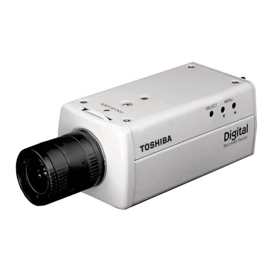
CCD COLOR CAMERA
IK-6550A
Please read this manual thoroughly before use, and keep it handy
for future reference.
TABLE OF CONTENTS
IMPORTANT SAFEGUARDS ................................................ 2
1. FEATURES & DESCRIPTION ...................................... 4
2. COMPONENTS ............................................................ 4
3. PART NAMES & FUNCTIONS ...................................... 5
4. CAMERA INSTALLATION ............................................. 6
5. CONNECTIONS AND OPERATIONS .......................... 7
6. LENS ............................................................................ 9
7. LINE-LOCK PHASE ...................................................... 10
8. MENU-DRIVEN SET-UP ............................................... 11
9. MENU LIST AND SETTINGS ....................................... 26
10. NOTES ON USE AND INSTALLATION ........................ 27
11. IN CASE OF PROBLEMS ............................................ 27
12. SPECIFICATIONS ........................................................ 28
13. EXTERIOR VIEW ......................................................... 29
INSTRUCTION MANUAL
Record in space provided below the Model No. and
the Serial No. as found on the label on the bottom
of this unit.
Model. No. IK-6550A
Retain this information for future reference.
Serial No.
Advertisement
Table of Contents

Related Manuals for Toshiba IK-6550A


Summary of Contents for Toshiba IK-6550A
-
Page 1: Table Of Contents
13. EXTERIOR VIEW ... 29 INSTRUCTION MANUAL Record in space provided below the Model No. and the Serial No. as found on the label on the bottom of this unit. Model. No. IK-6550A Serial No. Retain this information for future reference. -
Page 2: Important Safeguards
IMPORTANT SAFEGUARDS 1. Read Instructions All the safety and operating instructions should be read before the product is operated. 2. Retain Instructions The safety instructions and instruction manual should be retained for future reference. 3. Comply Warning Comply with all warnings on the product and in the instruction manual. - Page 3 CAUTION TO REDUCE THE RISK OF ELECTRIC SHOCK. DO NOT REMOVE COVER (OR BACK). NO USER SERVICEABLE PARTS INSIDE. REFER SERVICING TO QUALIFIED SERVICE PERSONNEL. The lightening flash with arrowhead symbol, within an equilateral triangle, is intended to alert the user to the presence of uninsulated “dangerous voltage”...
-
Page 4: Features & Description
1. FEATURES & DESCRIPTION 1. 24V AC/12V DC dual-voltage capable extends power choice. 2. Setting and adjustments are made by way of on-screen menu. (Menu Driven Set-Up) 3. Camera has the ability to automatically switch the display to color in daylight or black and white at night. -
Page 5: Part Names & Functions
3. PART NAMES & FUNCTIONS - 5 -... -
Page 6: Camera Installation
4. CAMERA INSTALLATION Installation Example 1/4"-20UNC The installation guide is for reference only. Mounting backet is not included. Wall 9.5 mm - 6 -... -
Page 7: Connections And Operations
5. CONNECTIONS AND OPERATIONS • Power plugs of connected equipment must be disconnected before installations. • A 75-ohm coaxial cable with connector (3C-2V or 5C-2V) is required for standard connection. • For details of wiring and operation of equipment to be connected, refer to their operation manuals. - Page 8 5-2. Line-Lock Control • Matching the vertical synchronization with the power frequency is called the Line-Lock. • This function is activated when the SYNC menu is selected to LL. • When two or more cameras are switched by the video switcher for viewing by a monitor TV, the vertical sync.
-
Page 9: Lens
6. LENS Back-Focus Adjusment Back-Focus is adjusted at the factory to accommodate most standard lenses. However, at times, slight adjustment to the IK-6550A back- focus is necessary. Loosen the Focus Lock Screw. Achieve a clear image by rotating the focus ring. -
Page 10: Line-Lock Phase
7. LINE-LOCK PHASE If two or more cameras within a system have different AC line phases are switched by the video switcher, the picture on the monitor TV will fluctuate vertically. Connect 24V AC input lines of all cameras so that they all share the same phase. -
Page 11: Menu-Driven Set-Up
8. MENU-DRIVEN SET-UP The setting menus of hierarchy are shown below and with on-screen character displays. MENU CAMERA SETUP D/N MODE D/N LEVEL SHUTTER SHARPNESS <OPTION> PRIVACY ZONE ZONE 1 ~ 8 CAMERA ID CAMERA ID EXIT CANCEL DEFAULT AUTO COLOR AUTO 1/60... - Page 12 8-1. Setting switches and the functions On the side panel of the cameras there are three push button switches as shown below: Switch name SELECT switch button button Main function Setting mode call on/off, setting entry Setting item selection (down) Setting item selection (up) - 12 - SELECT switch...
- Page 13 8.2 Setting mode call and basics <CAMERA SETUP> Press the SELECT switch down about 2 seconds then menu will appear on the display. Use the buttons to select <CAMERA SETUP>. 8-2-1. D/N MODE (DAY/NIGHT MODE) Selections: AUTO (default): The camera will sense the brightness level and switches to color mode or monochrome mode.
- Page 14 8-2-2. D/N LEVEL (DAY/NIGHT LEVEL) Selections: LOW (default): The chroma cut level is set less than 20 to 30 IRE. MID: The chroma cut level is set less than 30 to 40 IRE. HIGH: The chroma cut level is set less than 40 to 50 IRE.
- Page 15 8-2-4. GAIN (AGC) Selections: OFF: AGC does not operate. STD (default): Standard position, max gain = 24dB HIGH: High-Sensitivity position, max gain = 30dB Process: 1. Position the cursor ( ) next to CAMERA SETUP and press the SELECT switch to access the camera menu.
- Page 16 8-2-6. BLC (BACK LIGHT COMPENSATION) Selections: When using the automatic electronic iris with an auto iris lens, the exposure adjustment is automatically performed so that the best picture is obtained at the next monitor zone. The four different BLC zones are displayed below: Process: 1.
- Page 17 8-2-7. SHARPNESS Selections: Adjust the outline correction. LOW: to make the outline softer. MID (default): to make the outline standard. HIGH: to make the outline clearer Process: 1. Position the cursor ( ) next to CAMERA SETUP and press the SELECT switch to access the camera menu.
- Page 18 8-2-9. <OPTION> (1) DNR (DIGITAL NOISE REDUCTION) Selections: LOW: Enables minimum noise reduction. MID (default): Enables standard noise reduction. HIGH: Enables maximum noise reduction. Process: 1. Position the cursor ( ) next to CAMERA SETUP and press the SELECT switch to access the camera menu.
- Page 19 (3) BACK Position the cursor ( ) next to BACK and press the SELECT switch to exit OPTION menu. 8-2-10. BACK Position the cursor ( ) next to BACK and press the SELECT switch to exit CAMERA SETUP menu. CHROMA BACK D/N MODE AUTO...
- Page 20 8-2-11. <PRIVACY ZONE> Press the SELECT switch down about 2 seconds then menu will appear on the display. Use the buttons to select <PRIVACY ZONE>. Process: 1. Position the cursor ( ) next to PRIVACY ZONE and press the SELECT switch to access the menu. 2.
- Page 21 4. Use the buttons to set ZONE POSI (H) and press the SELECT switch. 5. Use the buttons to set ZONE POSI (V) and press the SELECT switch. ZONE 1 ZONE 2 ZONE 3 ZONE 4 ZONE 5 ZONE 6 ZONE 7 ZONE 8 BACK...
- Page 22 6. Use the buttons to set ZONE SIZE (H) and press the SELECT switch. 7. Use the buttons to set ZONE SIZE (V) and press the SELECT switch. 8-2-12. BACK Position the cursor ( ) next to BACK and press the SELECT switch to exit PRIVACY ZONE menu.
- Page 23 <CAMERA ID> Press the SELECT switch down about 2 seconds then menu will appear on the display. Use the buttons to select <CAMERA ID>. 8-2-13. CAMERA ID Position the cursor ( ) next to CAMERA ID and press the SELECT switch to access the CAMERA ID menu. Position the cursor ( ) next to CAMERA ID and press the SELECT switch.
- Page 24 8-2-14. ID POS (ID POSITION) Selections: OFF (default): Disappear the CAMERA ID. TOP: Show the ID position top-left of screen. BOTTOM: Show the ID position bottom-left of screen. Process: 1. Position the cursor ( ) next to CAMERA ID and press the SELECT switch to access the camera menu.
- Page 25 8-2-16. EXIT (save the changed settings) Position the cursor ( ) next to EXIT and press the SELECT switch to exit menu. 8-2-17. CANCEL (discard the changed settings) Position the cursor ( ) next to CANCEL and press the SELECT switch twice to load cancel settings. 8-2-18.
-
Page 26: Menu List And Settings
9. MENU LIST AND SETTINGS Top Menu Sub Menu 1 CAMERA SETUP D/N MODE D/N LEVEL SHUTTER GAIN SYNC SHARPNESS OPTION PRIVACY ZONE ZONE 1~8 CAMERA ID CAMERA ID ID POS Sub Menu 2 Contents AUTO / COLOR / B/W LOW / MID / HIGH IRIS AUTO / 1/60 1/100 1/250 1/500... -
Page 27: Notes On Use And Installation
10. NOTES ON USE AND INSTALLATION • Do not aim the camera at the sun Never aim the camera at the sun even with the camera power off. • Do not shoot intense light Intense light such as a spotlight may cause a bloom or smear. A vertical stripe may appear on the screen. -
Page 28: Specifications
12. SPECIFICATIONS Power Power consumption Image sensor Image pickup area Effective picture element Scanning system Scanning frequency Synchronization Resolution Minimum illuminance of subject Video output Output impedance White balance Iris control Gain control Backlight compensation Lens mount Ambient temperature Ambient humidity Weight External dimensions Automatic electronic shutter... -
Page 29: Exterior View
13. EXTERIOR VIEW - 29 -... - Page 30 MEMO...
- Page 31 MEMO...
-
Page 32: Limited Warranty
Product, if it does not perform as warranted. In order to take advantage of this Limited Warranty. You must: (a) call (877) 855-1349 to receive a RMA number: and (b) pay all transportation and insurance charges for shipment of the Product to the ASP or Toshiba Exchange Center.