Advertisement
Quick Links
Advertisement

Related Manuals for ABB ACS880-1604LC


Summary of Contents for ABB ACS880-1604LC
- Page 1 — ABB INDUSTRIAL DRIVES ACS880-1604LC DC/DC converter modules Hardware manual...
- Page 3 ACS880-1604LC DC/DC converter modules Hardware manual Table of contents 4. Cabinet construction 6. Electrical installation 8. Start-up © 2019 ABB Oy. All Rights Reserved. 3AXD50000371631 Rev A EFFECTIVE: 2019-06-28...
-
Page 5: Table Of Contents
Table of contents 5 Table of contents 1 Introduction to the manual Contents of this chapter ................Applicability ..................Safety instructions ................Target audience ................... Categorization by frame size and option module ..........Use of component designations ..............Terms and abbreviations ................. Related documents ................ -
Page 6: Table Of Contents
Layout without DC switch/disconnector and charging ........ Pipe routing example ..............Installation stages ................Kits for ACS880-1604LC R8i unit in Rittal VX25 cabinets ......Stage 1: Installation of common parts ..........Stage 2: Side plates, busbars and quick connectors for connecting DDC module and filter .................. -
Page 7: Table Of Contents
Table of contents 7 Electrical safety precautions ..............General notes ..................Printed circuit boards ................. Optical components ................Checking the insulation of the energy storage cable ........Connecting the power cables ..............Connection diagram (frame 1×R8i) ............Connection procedure for power connections inside the DC/DC converter cubicle .. Connection procedure of the energy storage cables ........ -
Page 8: Table Of Contents
8 Table of contents Replacing the BCU control unit battery ............ LEDs and other status indicators ............... 10 Ordering information Contents of this chapter ................Kit code key ..................DC/DC converter modules ............... BDCL filters ..................Control panel ..................Control electronics ................Control unit .................. -
Page 9: Table Of Contents
Table of contents 9 Draining the internal cooling circuit ............. Maintenance intervals ................Technical data ..................Coolant specification ................Coolant type ................Temperature limits ................Pressure limits ................. Coolant flow rate limits ............... Cooling circuit materials ..............12 Technical data Contents of this chapter ................ -
Page 10: Table Of Contents
15 Example circuit diagrams Contents of this chapter ................Content of the circuit diagrams ..............ACS880-1604LC DC/DC converter unit 1×R8i, 3AXD10000878887 ....ACS880-1604LC DC/DC converter unit 2×R8i, 3AXD10000873230 ....DDC 1×R8i with DC switch/disconnector ............. Sheet 001a (Main supply) .............. -
Page 11: Table Of Contents
Table of contents 11 Sheet 021a (Auxiliary voltage distribution) ..........Sheet 022a (24 V DC distribution) ............Sheet 026a (Cabinet fans) ..............Sheet 040a (Control board) ..............Sheet 040b (Control board) ..............Sheet 040c (Control board) ..............Sheet 040d (Signal lamps) ..............DDC 2×R8i with DC switch/disconnector ............. -
Page 13: Contents Of This Chapter
Introduction to the manual Contents of this chapter This chapter gives basic information on the manual. Applicability The manual is applicable to ACS880-1604LC DC/DC converter modules for user-defined cabinet installations. Safety instructions Follow all safety instructions delivered with the drive. -
Page 14: Categorization By Frame Size And Option Module
14 Introduction to the manual The manual is written for readers worldwide. Both SI and imperial units are shown. Categorization by frame size and option module Some descriptions, instructions and technical data which concern only certain module or frame sizes are marked with the size identifier (such as "2×R8i", etc.). The marking derives from the quantity and basic construction of the converter modules that form the converter unit. -
Page 15: Related Documents
ACS880 primary control program quick start-up guide 3AUA0000098062 Brake module and DC/DC converter module manuals ACS880-604LC 1-phase brake chopper modules hardware manual 3AXD50000184378 ACS880-1604LC DC/DC converter modules hardware manual 3AXD50000371631 ACS880 DC/DC converter control program firmware manual 3AXD50000024671 Option manuals... - Page 17 Each parallel module must have the output cabling of its own. We also recommend that you use identical cablings (cable type, cross-sectional area, and length) and have identical load for each module. For other solutions, contact ABB. Typically, the DC/DC converter is used in marine applications for heave compensation, peak load compensation, propulsion supply in harbors, energy storing instead of an additional generator and so on.
-
Page 18: Main Circuit Diagram
18 Operation principle and hardware description ■ Main circuit diagram The DC/DC converter module must be equipped with external DC fuses. You can equip the converter with a DC switch/disconnector, if quick isolation of the module from the DC bus is required. - Page 19 Operation principle and hardware description 19 This figure shows a simplified main circuit diagram of parallel-connected DC/DC converter modules with the DC switch/disconnector and charging circuit. Also the energy storage and related cabling and equipment are visible. DC/DC converter cubicles Energy storage cabinet Drive DC bus DC switch/disconnector...
-
Page 20: Overview Diagram Of A Drive With A Dc/Dc Converter Unit
20 Operation principle and hardware description Overview diagram of a drive with a DC/DC converter unit This diagram shows a possible application of a converter unit in an example system. The DC/DC converter unit includes a DC/DC converter module and a filter module. t°... -
Page 21: Single-Line Circuit Diagram Of The Dc/Dc Converter Unit
The connection is the same in both Rittal VX25 and generic enclosures. The table gives explanations for the numbers and letters of the diagram. It also indicates if customer can order the components from ABB or if the customer needs to acquire them separately. -
Page 22: Converter Module Hardware
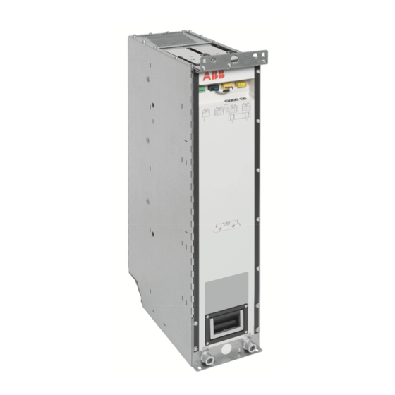
22 Operation principle and hardware description Converter module hardware ■ Module layout DC connection busbars, + (a) and - (b) Lifting eyes, front (a) and back (b) Coolant in (a) and out (b) connectors Handle Fiber optic connectors Quick connector (AC connection) (the counterpart fastened to the cabinet behind the module) Terminal block X50 (auxiliary power input for internal boards) Terminal block X51 and X52 (Safe torque off in inverter modules only) Terminal block X53 (24 V DC power output) -
Page 23: Connectors X50...X59
Operation principle and hardware description 23 ■ Connectors X50…X59 R8i modules contain a power supply (BDPS) that provides 24 V DC for the circuit boards of the module. The 24 V DC voltage provided by the BDPS is also available on X53, and can be used to power the BCU control unit of a single R8i module. -
Page 24: Fiber Optic Connectors
24 Operation principle and hardware description AC IN Auxiliary voltage inputs for internal power supply (BDPS) 24V OUT 24 V DC output (for eg. BCU control unit) STO IN STO connectors of the module. Must be connected to 24 V DC for the supply module to start. -
Page 25: Bdcl Filter Module
Operation principle and hardware description 25 The user must install a capacitor charging circuit if • the converter module is connected to the DC bus through a DC switch/disconnector, • the converter unit is directly connected to the DC bus and the supply unit of the system does not have charging circuit capability. -
Page 26: Overheating Protection Of The Filter
26 Operation principle and hardware description ■ Overheating protection of the filter By default, the BDCL filter is protected against overheating (caused by a faulty fan, for example) with a thermistor and the temperature monitoring function of the control program. If the filter temperature becomes too high, the temperature monitoring function stops the DC/DC converter module automatically. -
Page 27: Overview Of The Control Connections Of The Bcu Control Unit
Operation principle and hardware description 27 Overview of the control connections of the BCU control unit The diagram shows the control connections and interfaces of the BCU control unit. Analog and digital I/O extension modules and Control panel. fieldbus communication modules can be inserted into slots 1, 2 and 3. -
Page 28: Converter Unit Control Devices
28 Operation principle and hardware description Converter unit control devices ■ DC switch/disconnector You can equip the DC/DC converter cabinet with DC switch/disconnector [Q11]. A converter unit with a DC switch/disconnector must also have a precharge circuit including a charging switch. -
Page 29: Pc Connection
Operation principle and hardware description 29 To change between local and remote control mode, press the Loc/Rem key of the control panel. For the instructions on the use of the panel, see ACX-AP-x Assistant control panels user's manual (3AUA0000085685 [English]). For the parameter settings, see the firmware manual. -
Page 30: Type Designation Labels
30 Operation principle and hardware description Type designation labels ■ Type designation labels of the DC/DC converter module Each DC/DC converter module has type designation labels attached to it. The type designation stated on the labels contains information on the specifications and configuration of the unit. -
Page 31: Type Designation Label Of The Bdcl Filter Module
Operation principle and hardware description 31 ■ Type designation label of the BDCL filter module Each filter module has a type designation label attached to it. Quote the complete type designation and serial number when contacting technical support on the subject of individual filter modules. An example label is shown below. -
Page 32: Type Designation Key
32 Operation principle and hardware description Type designation key ■ Type designation key of the module Type designation describes the composition of the module in short. The complete designation code is divided in subcodes: • The first digits form the basic code. It describes the basic construction of the module. The fields in the basic code are separated by hyphens. - Page 33 Moving and unpacking the module 33 Moving and unpacking the module Contents of this chapter This chapter gives basic information on unpacking and moving the module. WARNING! For the safety instructions, see Safety instructions for ACS880 liquid-cooled multidrive cabinets and modules (3AXD50000048633 [English]). Moving and unpacking the module The modules are delivered on a wooden base, boxed in corrugated cardboard.
- Page 35 The installation must always be designed and made according to applicable local laws and regulations. ABB does not assume any liability whatsoever for any installation which breaches the local laws and/or other regulations. Furthermore, if the recommendations given by ABB are not followed, the drive may experience problems that the warranty does not cover.
-
Page 36: Cabinet Configuration Overview
36 Cabinet construction Cabinet configuration overview This figure shows the DC/DC converter configuration of 1×R8i and 2×R8i units installed in the Rittal VX25 or generic enclosures. BD CL BD CL BD CL BD CL BD CL BD CL BD CL BD CL BD CL BDCL... -
Page 37: Installation Examples
You can find the kit-specific assembly drawings, step-by-step instructions and kit information on the Internet. Go to https://sites-apps.abb.com/sites/lvacdrivesengineeringsupport/content. If needed, contact your local ABB representative. The example includes also cabinet assembly drawings that show each stage listed in the table. More detailed steps of each stage are described in the kit-specific assembly drawings. -
Page 38: R8I Ddc Unit In Rittal Vx25 Enclosure
38 Cabinet construction ■ 1×R8i DDC unit in Rittal VX25 enclosure Layout with DC switch/disconnector and charging This figure shows an example of the DC/DC converter unit in the Rittal VX25 enclosure. The unit includes an R8i DC/DC converter module, a BDCL filter module, bottom cable entries for the energy storage connection, DC switch/disconnector and charging components. -
Page 39: Layout Without Dc Switch/Disconnector And Charging
Cabinet construction 39 Layout without DC switch/disconnector and charging This figure shows an example of the DC/DC converter unit in the Rittal VX25 enclosure without DC switch/disconnector and charging. The unit includes an R8i DC/DC converter module, a BDCL filter module and bottom cable entries for the energy storage connection. Description Cubicle including: 1. -
Page 40: Pipe Routing Example
40 Cabinet construction Pipe routing example Coolant IN Inlet manifold with stop and drain valves Heat exchanger DC/DC converter module BDCL filter module Outlet manifold with stop and drain valves Coolant OUT... -
Page 41: Installation Stages
Cabinet construction 41 Installation stages Installation stage Instruction code Kit code Kit ordering code Installation of common parts: Baying parts 3AXD50000336340 Flat-PLS support kit 3AXD50000333639 3AXD50000333387 Sideplates, busbars and quick connectors for connecting DDC module and filter Side plate kit 3AXD50000327591 L-468-8-020-VX 3AXD50000360543... -
Page 42: Kits For Acs880-1604Lc R8I Unit In Rittal Vx25 Cabinets
42 Cabinet construction Kits for ACS880-1604LC R8i unit in Rittal VX25 cabinets... -
Page 43: Stage 1: Installation Of Common Parts
Cabinet construction 43 Stage 1: Installation of common parts... -
Page 44: Stage 2: Side Plates, Busbars And Quick Connectors For Connecting Ddc Module And Filter
44 Cabinet construction Stage 2: Side plates, busbars and quick connectors for connecting DDC module and filter... -
Page 45: Stage 3: Module Installation Parts
Cabinet construction 45 Stage 3: Module installation parts... -
Page 46: Stage 4: Ddc And Energy Storage Connection
46 Cabinet construction Stage 4: DDC and energy storage connection... -
Page 47: Stage 5A: Dc Connection With Charging
Cabinet construction 47 Stage 5A: DC connection with charging... -
Page 48: Stage 5B: Dc Connection Without Charging
48 Cabinet construction Stage 5B: DC connection without charging... -
Page 49: Stage 6: Cooling Components
Cabinet construction 49 Stage 6: Cooling components... -
Page 50: Stage 7: Ddc Module And Filter Installation
50 Cabinet construction Stage 7: DDC module and filter installation... -
Page 51: Stage 8: Swing Frame And Shroud Installation
Cabinet construction 51 Stage 8: Swing frame and shroud installation... -
Page 52: R8I Ddc Unit
52 Cabinet construction ■ 2×R8i DDC unit This section contains the information on the parallel connection installation stage. Otherwise the installation stages of the 2×R8i configuration are identical with the 1×R8i configuration. Do the parallel connection as the first installation stage for 2×R8i configuration, and continue with the installation stages presented for the 1×R8i configuration. - Page 53 The installation must always be designed and made according to applicable local laws and regulations. ABB does not assume any liability whatsoever for any installation which breaches the local laws and/or other regulations. Furthermore, if the recommendations given by ABB are not followed, the drive may experience problems that the warranty does not cover.
-
Page 54: Selecting The Energy Storage
54 Guidelines for planning electrical installation Selecting the energy storage WARNING! ABB is not responsible for the energy storage selection or protection of the energy storage. The energy storage does not belong to the converter unit delivery. The customer (or the system integrator) must equip the DC/DC converter with a suitable energy storage system. -
Page 55: Implementing Protections For The Energy Storage
■ Protecting the energy storage cable ABB equips the DC/DC converter unit with fuses as standard. The fuses protect the DC/DC converter and cables in a cable short-circuit situation. The customer (or the system integrator) must equip the energy storage with overload and short circuit protection for the cable. -
Page 56: Implementing An Interlocking Between The Disconnecting Devices
56 Guidelines for planning electrical installation ■ Implementing an interlocking between the disconnecting devices The customer (or the system integrator) must implement an interlocking circuit between the DC switch/disconnector of the DC/DC converter unit and the energy storage disconnector. The user must not be able to close the energy storage disconnector before closing the DC switch/disconnector [Q11] of the DC/DC converter. -
Page 57: Emc Compliance Of The Complete Installation
■ EMC compliance of the complete installation Note: ABB has not verified that the EMC requirements are fulfilled with external energy storage and its cabling. The EMC compliance of the complete installation must be considered by the customer (or the system integrator). - Page 59 The installation must always be designed and made according to applicable local laws and regulations. ABB does not assume any liability whatsoever for any installation which breaches the local laws and/or other regulations. Furthermore, if the recommendations given by ABB are not followed, the drive system may experience problems that the warranty does not cover.
-
Page 60: Electrical Safety Precautions
60 Electrical installation Electrical safety precautions These electrical safety precautions are for all personnel who do work on the drive, motor cable or motor. WARNING! Obey these instructions. If you ignore them, injury or death, or damage to the equipment can occur. If you are not a qualified electrician, do not do installation or maintenance work. -
Page 61: General Notes
Electrical installation 61 7. Install temporary grounding as required by the local regulations. 8. Ask the person in control of the electrical installation work for a permit to work. General notes ■ Printed circuit boards WARNING! Use a grounding wrist band when you handle printed circuit boards. Do not touch the boards unnecessarily. -
Page 62: Checking The Insulation Of The Energy Storage Cable
62 Electrical installation Checking the insulation of the energy storage cable WARNING! Obey the safety instructions given in Safety instructions for ACS880 liquid-cooled multidrive cabinets and modules (3AXD50000048633 [English]). If you ignore the safety instructions, injury or death, or damage to the equipment can occur. -
Page 63: Connecting The Power Cables
Electrical installation 63 Connecting the power cables ■ Connection diagram (frame 1×R8i) DC/DC converter cubicle Energy storage cubicle Charging circuit components (For charging circuit connections, see the example circuit diagrams.) DC/DC converter module (R8i) BDCL filter module Shielded 3-conductor or 4-conductor cable and 360 degree grounding of the cable shield at the cable entry. -
Page 64: Connection Procedure For Power Connections Inside The Dc/Dc Converter Cubicle
64 Electrical installation ■ Connection procedure for power connections inside the DC/DC converter cubicle WARNING! Obey the safety instructions given in Safety instructions for ACS880 liquid-cooled multidrive cabinets and modules (3AXD50000048633 [English]). If you ignore the safety instructions, injury or death, or damage to the equipment can occur. -
Page 65: Connection Procedure Of The Energy Storage Cables
Electrical installation 65 5. Refit any shrouding removed earlier and close the cubicle doors. ■ Connection procedure of the energy storage cables Make sure that the converter and filter modules, and other components of the DC/DC converter unit has been installed in a cabinet, in other words, the mechanical installation has been done. - Page 66 66 Electrical installation 9. At the energy storage, connect the cables according to the instructions of the energy storage manufacturer. This is an example of a cable entry that the cabinet installer has to acquire and install in the cabinet.
-
Page 67: Connecting The Bdcl Filter
3. Connect the thermistor input [XD1] of the converter control unit to the filter thermistors [X30:5, X30:6]. WARNING! Do not disable the module temperature monitoring function. WARNING! Use the BDCL filter only with an ACS880-1604LC DC/DC converter module ■ Internal circuit diagram for the BDCL filter... -
Page 68: Installing The Charging Circuit
Installing the charging circuit The cabinet builder must install and connect the charging circuit. For connections, see the example circuit diagrams. Consult ABB for more information on the components and wirings needed. Activate and tune the charging function in the control program. For information on tuning the parameters, see ACS880 DC/DC converter control program firmware manual (3AXD50000024671 [English]). -
Page 69: Connecting The Control Cables
Electrical installation 69 Connecting the control cables ■ Default I/O connection diagram Control units of the drive. ■ Connection procedure Note: The instructions below are based on an example cabinet construction. They are not applicable to all possible solutions but only clarify the principles. The following procedure instructs how to connect the control cables of a DC/DC converter unit. - Page 70 70 Electrical installation 6. Strip the cable ends and conductors. When connecting to the drive I/O, also remove the shield along with the outer sheathing, and use electrical tape or shrink tubing to contain the strands. Elsewhere, twist outer shield strands into a bundle, crimp a lug onto it and connect it to the nearest chassis grounding point.
-
Page 71: Installing Optional Modules
Electrical installation 71 Installing optional modules WARNING! Obey the safety instructions of the drive. If you ignore them, injury or death, or damage to the equipment can occur. Note: Pay attention to the free space required by the cabling or terminals coming to the optional modules. - Page 73 Installation checklist of the drive 73 Installation checklist of the drive Contents of this chapter This chapter contains a checklist of the mechanical and electrical installation of the drive. Checklist Examine the mechanical and electrical installation of the drive before start-up. Go through the checklist together with another person.
- Page 74 74 Installation checklist of the drive Make sure that … The main circuit connections inside the drive cabinet correspond to the circuit diagrams. The control unit has been connected. See the circuit diagrams. Appropriate AC fuses and main disconnector have been installed. There is an adequately sized protective earth (ground) conductor between the drive and the switchboard, the conductor has been connected to appropriate terminal, and the terminal has been tightened to the proper torque.
- Page 75 ABB. WARNING! Only qualified by ABB electricians/engineers are allowed to do the work described in this chapter. In addition, the electrician/engineer must know the energy storage system he is about to take into use, and the DC/DC converter control program and operation principle.
-
Page 76: Start-Up Procedure
Note: If the drive has been stored over one year: Reform the electrolytic DC capacitors in the DC bus of the drive. See the separate reforming instructions (available in the Internet or from your local ABB repres- entative). Close the auxiliary voltage circuit breakers of the converter unit [F21, F22]. Close also other circuit breakers of the converter auxiliary circuits: cabinet fans [F115] and BAMU voltage/current measurement [F7] if present and the auxiliary voltage switch of the drive supply unit. - Page 77 Start-up 77 Tasks Make sure that the coolant can flow freely in all cubicles. Close the cabinet doors. Connecting voltage to the drive and converter control unit Connect main AC voltage to the input terminals of the drive supply unit. (Close the main breaker of the supply transformer.) WARNING! When connecting voltage to the supply unit, the DC busbars will become live, as will all the...
- Page 78 78 Start-up Tasks Connecting the energy storage to the DC/DC converter Set parameter 120.12 Run enable 1 to Off. This makes sure that the DC/DC converter does not start automatically or unexpectedly after you connect the energy storage. Switch the control panel to local control mode. Make sure that the energy storage voltage is below the drive DC link voltage.
-
Page 79: Disconnecting The Dc/Dc Converter With Dc Switch/Disconnector
Start-up 79 Disconnecting the DC/DC converter with DC switch/disconnector Tasks Safety WARNING! Obey the safety instructions during the start-up procedure. See Safety instructions for ACS880 liquid-cooled multidrive cabinets and modules (3AXD50000048633 [English]). If you ignore the safety instructions, injury or death, or damage to the equipment can occur. -
Page 80: Reconnecting The Dc/Dc Converter With Dc Switch/Disconnector
80 Start-up Reconnecting the DC/DC converter with DC switch/disconnector Tasks Safety WARNING! Obey the safety instructions during the start-up procedure. See Safety instructions for ACS880 liquid-cooled multidrive cabinets and modules (3AXD50000048633 [English]). If you ignore the safety instructions, injury or death, or damage to the equipment can occur. - Page 81 If you are not a qualified electrician, do not do installation or maintenance work. Maintenance intervals The table below shows the maintenance tasks which can be done by the end user. The complete maintenance schedule is available on the Internet (www.abb.com/drivesservices). For more information, consult your local ABB Service representative (www.abb.com/searchchannels).
-
Page 82: Maintenance Timers And Counters
Performance of on/off-site work (commissioning, tests, measurements or other work) Replacement Maintenance and component replacement intervals are based on the assumption that the equipment is operated within the specified ratings and ambient conditions. ABB recommends annual drive inspections to ensure the highest reliability and optimum performance. Note: Long term operation near the specified maximum ratings or ambient conditions may require shorter maintenance intervals for certain components. -
Page 83: Power Connections
Maintenance 83 Power connections ■ Retightening the power connections WARNING! Read the safety instructions given in Safety instructions for ACS880 liquid-cooled multidrive cabinets and modules (3AXD50000048633 [English]). If you ignore them, injury or death, or damage to the equipment can occur. 1. -
Page 84: Fans
84 Maintenance Fans The lifespan of the cooling fan depends on the running time of the fan, ambient temperature and dust concentration. Replacement fans are available from ABB. Do not use other than ABB specified spare parts. ■ Replacing the cooling fans WARNING! Obey the safety instructions of the drive. -
Page 85: Dc/Dc Converter Module
Maintenance 85 DC/DC converter module ■ Replacing the R8i DC/DC converter module WARNING! Obey the safety instructions given in Safety instructions for ACS880 liquid-cooled multidrive cabinets and modules (3AXD50000048633 [English]). If you ignore the safety instructions, injury or death, or damage to the equipment can occur. - Page 86 86 Maintenance 6. Close the inlet valve (a) and outlet valve (located on the right-hand side of the cubicle) valves. Lead the drain hoses (b, on both sides of the cubicle) into a suitable container. Open the drain valves (c, on both sides of the cubicle). This will drain all modules in the cubicle.
-
Page 87: Reinstalling The Module
Capacitor failure is usually followed by damage to the unit and an input cable fuse failure, or a fault trip. Contact ABB if capacitor failure is suspected. Replacements are available from ABB. Do not use other than ABB specified spare parts. Contact an ABB service representative for spare parts and repair services. -
Page 88: Control Unit
88 Maintenance Control unit ■ BCU control unit types There are three variants of the BCU control unit used in ACS880: BCU-02, BCU-12 and BCU-22. These have a different number of converter module connections (2, 7 and 12 respectively) but are otherwise identical. The three BCU types are interchangeable as long as the number of connections is sufficient. -
Page 89: Leds And Other Status Indicators
Maintenance 89 5. Set the real-time clock. LEDs and other status indicators This section instructs how to interpret the status indications of the ACS880-1604LC DC/DC converter. Warnings and faults reported by the control program are displayed on the control panel on the cabinet door. - Page 90 90 Maintenance The DC/DC converter module (frame R8i) has three LEDs. For their indications, see the following table. Location Indication DC/DC converter FAULT There is an active fault in the DC/DC converter module. module (continuous red) ENABLE / STO The DC/DC converter module is ready for use. (continuous green) ENABLE / STO XSTO connectors are de-energized.
- Page 91 Note: • This chapter only lists the installation accessories available from ABB. All other parts must be sourced from a third party (such as Rittal) by the system integrator. For a listing, refer to the kit-specific installation instructions available at https://sites-apps.abb.com/sites/lvacdrivesengineeringsupport/content.
- Page 92 92 Ordering information • L = liquid-cooled • w = cabinet width • 4 = 400 mm • 6 = 600 mm • 8 = 800 mm • s = module frame size / sizes • 1 = R1i • 2 = R2i •...
-
Page 93: Dc/Dc Converter Modules
Converter units consisting of frame R8i converter modules are to be ordered as separate modules. For converter unit ratings, see the technical data. DC/DC converter unit Modules used Ordering code Type Frame size (for options, see below) = 690 V ACS880-1604LC-0400A-7 ACS880-104LC-0480A-7+E205 ACS880-1604LC-0500A-7 ACS880-104LC-0530A-7+E205 ACS880-1604LC-0600A-7 ACS880-104LC-0600A-7+E205 ACS880-1604LC-0700A-7 ACS880-104LC-0670A-7+E205 ACS880-1604LC-0800A-7... -
Page 94: Bdcl Filters
• make the installation or use of the module easier. BDCL filters DC/DC converter L-filter unit type Frame size Type Ordering code ACS880-1604LC-… 0400A-7 BDCL-14LC-7 3AXD50000332687 0500A-7 BDCL-14LC-7 3AXD50000332687 0600A-7 BDCL-15LC-7 3AUA0000190873 0700A-7... -
Page 95: Control Panel
Ordering information 95 114 Ordering information Control panel Control panel The control panel is not included with the module but must be ordered separately. One The control panel is not included with the supply module but must be ordered separately. control panel is required for the commissioning of an ACS880 drive system, even if the Drive One control panel is required for the commissioning of an ACS880 drive system, even if composer PC tool is used. -
Page 96: Control Electronics
• memory unit with DC/DC converter control program. You must connect the control unit to each DC/DC converter module with a pair of fiber optic cables. You can order them from ABB. See section Fiber optic cables (page 97). You can supply 24 V DC for the control unit from the DC/DC converter module. (Alternatively, you can take the power supply from another suitable power source). -
Page 97: Fiber Optic Cables
The following kits, each consisting of a pair of plastic fiber optic cables, are available from ABB: Length Kit type designation Ordering code NLWC-02 58988821 NLWC-03 58948233 NLWC-05 58948250 NLWC-07 58948268 10 m NLWC-10 58948276 ■ Options For more information related to available control panel, fieldbus, I/O module and DDCS communication options, contact ABB. -
Page 98: Mechanical Installation Accessories
98 Ordering information Mechanical installation accessories ■ Module installation parts Module installation parts include top and bottom supports for the DC/DC converter and BDCL filter modules and side plate kit. Used with … Ordering code Kit code Illustration 1 per DC/DC Rittal VX25 en- converter mod- 3AXD50000360598... - Page 99 Ordering information 99 Used with … Ordering code Kit code Illustration 1 per DC/DC Rittal VX25 en- converter mod- 3AXD50000360543 L-468-8-020-VX closure Instruction code: 3AXD50000327591...
-
Page 100: Swing-Out Frame (For Rittal Vx25 Enclosures)
100 Ordering information ■ Swing-out frame (for Rittal VX25 enclosures) The swing-out frame is a hinged compartment that can be used as a mounting base for e.g. control electronics and auxiliary voltage circuit components. Used with … Ordering code Kit code Illustration 400 mm 1 per DC/DC... -
Page 101: Shrouds
Ordering information 101 ■ Shrouds Shrouds are used for IP20 touch protection with the cabinet doors open. Used with … Ordering code Kit code Illustration 1 per DC/DC 400 mm Rittal converter mod- 3AXD50000361083 L-4-8-022-VX VX25 enclosure Instruction code: 3AXD50000353354... -
Page 102: Bottom Cable Entry
102 Ordering information Used with … Ordering code Kit code Illustration 400 mm Rittal 1 per filter mod- 3AXD50000441822 L-4-8-030-VX VX25 enclosure Ordering information 117 Instruction code: 3AXD50000444106 AC-side components ■ Bottom cable entry Cable entry kit This kit is to be installed on the bottom plate of the enclosure. It contains four cable entries Cable entry kit, to be installed on the bottom plate of the enclosure, contains four 60 mm for energy storage cables with grommets, wire meshing for 360°... -
Page 103: Electrical Installation Accessories
Ordering information 103 Electrical installation accessories ■ Busbars and quick connectors for connecting DDC module and filter Busbars provide connection from the DC/DC converter module to the BDCL filter. Used with … Ordering code Kit code Illustration Rittal VX25 en- 3AXD50000437191 L-4-8-258-VX closure... - Page 104 104 Ordering information Used with … Ordering code Kit code Illustration Rittal VX25 en- 1 per cubicle 3AXD50000333387 A-468-X-001-VX closure Instruction code: 3AXD50000333639...
-
Page 105: Dc Connection With Dc Switch/Disconnector And Charging
Ordering information 105 ■ DC connection with DC switch/disconnector and charging You can equip the DC/DC converter with DC switch/disconnector if quick isolation of the module from DC bus is required. These parts provide the mounting base for the charging components and connect the converter module to the DC bus. -
Page 106: Dc Switch/Disconnector Kits
106 Ordering information In addition, you also need the DC switch kit and the charging kit. DC switch/disconnector kits Module type Frame Ordering code ACS880-1604LC-… = 690 V 0400A-7 0500A-7 0600A-7 SWITCH KIT OT-TYPE IEC 3AXD50000227037 1600 E11 24 V DC... -
Page 107: Charging Kits
Ordering information 107 Charging kits Module type Frame Ordering code ACS880-1604LC-… = 690 V 0400A-7 0500A-7 0600A-7 DC CHARGING KIT 1-2xR8i LC 3AXD50000226801 0700A-7 0800A-7 0900A-7 1000A-7 2×R8i 1200A-7 2×R8i 1400A-7 2×R8i DC CHARGING KIT 1-2xR8i LC 3AXD50000226801 1600A-7 2×R8i 1800A-7 2×R8i... -
Page 108: Dc Connection Without Dc Switch/Disconnector And Charging
108 Ordering information ■ DC connection without DC switch/disconnector and charging These kits provide the mounting base for the DC fuses and connect the converter module to the DC bus. Used with … Ordering code Kit code Illustration 400 mm Rittal VX25 en- closure with DC 3AXD50000360604... -
Page 109: Energy Storage Connection
3AXD50000438006 ■ DC fuses (DC bus side) DC fuses on the DC bus side protect the module and drive DC bus against short circuits. Fuse Module type Frame Ordering code ACS880-1604LC-… Type Rating = 690 V 0400A-7 170M6544 63903167 0500A-7... -
Page 110: Output Dc Fuses (Energy Storage Side)
■ Output DC fuses (energy storage side) DC fuses on the energy storage side protect the module against short circuits from the energy storage. Fuse Module type Frame Ordering code ACS880-1604LC-… Type Rating = 690 V 0400A-7 170M6544 63903167 0500A-7... -
Page 111: Cooling System Parts
Nipples for connecting the valves to manifolds Connectors for PA piping Plugs for unused piping connectors Chokes for flow limitation – not used with the ACS880-1604LC. You must order the following parts separately as they are not included in the manifold kits: •... -
Page 112: Piping
112 Ordering information ■ Piping The PA (polyamide) pipe can be used for all piping inside the cubicle between the manifolds. Component Ordering code PA pipe Data PA pipe 50 m, PA12P40, 16/13 mm 3AXD50000047488 Note: The piping between the manifolds and main pipes (1), and drain pipes (2) are not part of the offering. -
Page 113: Cooling Fan
Ordering information 113 ■ Cooling fan The fan blows air through the heat exchanger and the module, circulating the air inside the cabinet. The kit contains the fan installed into its cowling which mounts to the module bottom guide. The fan is selected according to the auxiliary voltage. Auxiliary voltage Ordering code Illustration... -
Page 114: Miscellaneous
114 Ordering information Miscellaneous ■ BAMU voltage/current measurement unit BAMU voltage/current measurement unit is not included in the module delivery but must be ordered separately. If you use BAMU to measure the energy storage voltage, the converter measures its output voltage (and thus also the energy storage voltage) automatically. You do not need any additional measurement for the converter. - Page 115 Internal cooling circuit 115 Internal cooling circuit Contents of this chapter The cooling system of a liquid-cooled drive consists of two circuits: the internal cooling circuit and the external cooling circuit. The internal cooling circuit covers the heat-generating electrical components of the drive and transfers the heat to the cooling unit. In the cooling unit, the heat is transferred to the external cooling circuit which is usually part of a larger external cooling system.
- Page 116 116 Internal cooling circuit Supply modules Inverter modules To/From cooling unit Air-to-liquid heat exchanger Heat sink Inlet valve Inlet-side drain valve Outlet valve Outlet-side drain valve The coolant used with ACS880 liquid-cooled drive systems is Antifrogen® L 25% or 50% water mixture.
-
Page 117: Connection To A Cooling Unit
Internal cooling circuit 117 Connection to a cooling unit ■ Connection to an ACS880-1007LC cooling unit Refer to ACS880-1007LC cooling unit user’s manual (3AXD50000129607 [English]). ■ Connection to a custom cooling unit General requirements Equip the system with an expansion tank to damp pressure rise due to volume changes when the temperature varies. -
Page 118: Filling Up And Bleeding The Internal Cooling Circuit
118 Internal cooling circuit Filling up and bleeding the internal cooling circuit Both the drive and coolant must be at room temperature before filling up the cooling circuit. WARNING! Make sure that the maximum permissible operating pressure is not exceeded. When necessary regulate the pressure to appropriate level by draining excess coolant out of the system. - Page 119 Internal cooling circuit 119 13. Start the coolant pump. Let any air remaining in the system out through the bleed valve at the cooling unit. 14. After one to two minutes, stop the pump or block the coolant flow with a valve. 15.
-
Page 120: Draining The Internal Cooling Circuit
Coolant type Antifrogen® L (by Clariant International Ltd, www.clariant.com) 25% or 50% water mixture, available from Clariant distributors and ABB Service representatives. Antifrogen® L 25% mixture is usable in storage temperatures down to -16 °C (3.2 °F). Antifrogen® L 50% mixture is usable in storage temperatures down to -40 °C (-40 °F). - Page 121 Internal cooling circuit 121 The higher the concentration of heat transfer fluid, the higher the viscosity of the coolant. This results in a higher pressure loss in the system. See Pressure limits (page 122). The nominal current ratings of drive system modules apply to an Antifrogen® L / water solution of 25/75% (volume).
-
Page 122: Pressure Limits
122 Internal cooling circuit Min. T (°C) coolant (°C) RH = 95% RH = 80% RH = 65% RH = 50% RH = 40% -0.1 -3.0 14.2 11.5 19.2 16.5 13.2 24.1 21.4 17.9 13.8 10.5 29.1 26.2 22.7 18.4 15.0 34.1 31.1... - Page 123 Internal cooling circuit 123 • rubber gasketing NBR (nitrile rubber). WARNING! If connecting external piping to the internal cooling circuit, use only materials that are specified above. Copper, brass or bronze must not be used under any circumstances. Even minor dissolution of copper can cause copper precipitation on aluminum and subsequent galvanic corrosion.
- Page 125 Technical data 125 Technical data Contents of this chapter This chapter contains technical data for ACS880-1604LC DC/DC converter modules.
-
Page 126: Ratings
126 Technical data Ratings No-overload use ACS880- contmax contmax max output Frame 1604LC-… input output A (DC) A (DC) A (DC) = 690 V 0400A-7 12000 0500A-7 12000 0600A-7 12000 0700A-7 12000 0800A-7 1000 12000 0900A-7 1060 1125 12000 1000A-7 2×R8i 1000 1178... -
Page 127: Derating
BDCL-15LC-7 1800A-7 1800A-7 0850A-7 2×R8i BDCL-15LC-7 Cabinet-installed units available from ABB DC/DC converter unit types available from ABB as modules R8i converter modules used. The quantity of the modules is shown in the frame column. BDCL filter type and quantity... -
Page 128: Fuses
128 Technical data Fuses The fuses are given in the ordering information. Losses and cooling data (conv.) (filter) total Pressure loss ACS880- loss loss loss Frame 1604LC-… = 690 V 0400A-7 0500A-7 0600A-7 0700A-7 0800A-7 0900A-7 1000A-7 2×R8i 11.2 1200A-7 2×R8i 10.6 13.6... -
Page 129: Dimensions And Weights
Technical data 129 Dimensions and weights ■ R8i DC/DC converter module The dimensions of a DC/DC converter module are: • height 880 mm • width 210 mm • depth 450 mm • weight 63 kg. For the number of R8i modules in a given DC/DC converter unit, see Type equivalence table. -
Page 130: Typical Power Cable Sizes
130 Technical data Typical power cable sizes The tables below give current carrying capacity (I ) for aluminum and copper PVC/XLPE Lmax insulated cables. A correction factor K = 0.70 is used. Time const is the temperature time constant of the cable. The cable sizing is based on max. - Page 131 Technical data 131 Copper cable PVC insulation XLPE insulation Conductor temperature 70° Conductor temperature 90° Size ⌀ [mm] Time const. [s] Time const. [s] Lmax Lmax 3 × 1.5 + 1.5 3 × 2.5 + 2.5 (3 × 4 + 4) 3 ×...
-
Page 132: Tightening Torques
Input power (DC bus) connection Voltage (U ACS880-1604LC-xxxxx-7 = 742 … 976 V DC. This is indicated in the type designa- tion label as typical input voltage levels 742 / 849 / 976 V DC (849 V DC for UL/CSA). -
Page 133: Output Power (Energy Storage) Connection
Maximum long-term tensile load: 1 N • Flexing: Max. 1000 cycles ABB drive products in general utilize 5 and 10 MBd (megabaud) optical components from Avago Technologies’ Versatile Link range. Note that the optical component type is not directly related to the actual communication speed. -
Page 134: Protection Classes
134 Technical data Note: The optical components (transmitter and receiver) on a fiber optic link must be of the same type. Plastic optical fiber (POF) cables can be used with both 5 MBd and 10 MBd optical components. 10 MBd components also enable the use of Hard Clad Silica (HCS®) cables, which allow longer connection distances thanks to their lower attenuation. - Page 135 Technical data 135 Contamination IEC/EN 60721-3-3:2002: IEC 60721-3-1 IEC 60721-3-2 Classification of environ- mental conditions - Part 3- 3: Classification of groups of environmental paramet- ers and their severities - Stationary use of weather protected locations Chemical gases Class 3C2 Class 1C2 Class 2C2 Solid particles...
-
Page 136: Materials
IEC 62635 guidelines. To aid recycling, plastic parts are marked with an appropriate identification code. Contact your local ABB distributor for further information on environmental aspects and recycling instructions for professional recyclers. End of life treatment must follow international and local regulations. -
Page 137: Applicable Standards
ABB and its affiliates are not liable for damages and/or losses related to such security breaches, any unauthorized... - Page 139 Control units of the drive 139 Control units of the drive Contents of this chapter This chapter • describes the connections of the control unit, • contains the specifications of the inputs and outputs of the control unit.
-
Page 140: Bcu-X2 Control Unit Layout And Connections
140 Control units of the drive BCU-x2 control unit layout and connections Description I/O terminals (see following diagram) SLOT 1 I/O extension, encoder interface or fieldbus adapter module connection. (This is the sole location for an FDPI-02 diagnostics and panel interface.) SLOT 2 I/O extension, encoder interface or fieldbus adapter module connection... - Page 141 Control units of the drive 141 Description Analog inputs Analog outputs Digital inputs, Digital input interlock (DIIL) XRO3 XD24 XPOW XDIO Digital input/outputs XD2D Drive-to-drive link XRO2 XDIO XD24 +24 V output (for digital inputs) XETH Ethernet port – Not in use XRO1 XPOW External power input...
-
Page 142: Default I/O Diagram Of The Converter Control Unit
142 Control units of the drive Default I/O diagram of the converter control unit The diagram below shows the default I/O connections on the converter control unit, and describes the use of the signals/connections. The wire size accepted by all screw terminals (for both stranded and solid wire) is 0.5 … 2.5 mm (24…12 AWG). -
Page 143: External Power Supply For The Control Unit (Xpow)
(nominal impedance 100 to 165 ohm, for example Belden 9842) for the wiring. For best immunity, ABB recommends high quality cable. Keep the cable as short as possible. Avoid unnecessary loops and parallel runs near power cables such as motor cables. -
Page 144: The X485 Connector
The BCU-x2 has an on-board data logger that collects real-time data from the power modules to help fault tracing and analysis. The data is stored onto the SDHC memory card inserted into the SD CARD slot and can be analyzed by ABB service personnel. -
Page 145: Connector Data
Power supply Connector pitch 5 mm, wire size 2.5 mm (XPOW) 24 V (±10%) DC, 2 A Control units of the drive 145 External power input. Two supplies can be connected for redundancy. Relay outputs RO1…RO3 Connector data Connector pitch 5 mm, wire size 2.5 mm (XRO1…XRO3) 250 V AC / 30 V DC, 2 A Power supply (XPOW) - Page 146 146 Control units of the drive Analog inputs AI1 and AI2 Connector pitch 5 mm, wire size 2.5 mm (XAI:4 … XAI:7). Current input: –20…20 mA, R = 100 ohm Current/voltage input mode selection by Voltage input: –10…10 V, R >...
-
Page 147: Bcu-X2 Ground Isolation Diagram
Control units of the drive 147 Control units of the drive 137 ■ BCU-x2 ground isolation diagram Ground isolation diagram XPOW +24VI +24VI +VREF -VREF AGND AI1+ Common mode voltage AI1- AI2+ between each AI input and AI2- AGND is +30 V AGND AGND XD2D... - Page 149 Dimension drawings 149 Dimension drawings Contents of this chapter This chapter shows the dimensions of the ACS880-1604LC DC/DC converter modules and accessories.
-
Page 150: R8I Dc/Dc Converter Module
150 Dimension drawings R8i DC/DC converter module... - Page 151 Dimension drawings 151 BDCL filter module...
-
Page 152: Quick Connector
152 Dimension drawings Quick connector... -
Page 153: Bcu Control Unit
Dimension drawings 153 BCU control unit... -
Page 154: Bamu Voltage/Current Measurement Unit
154 Dimension drawings BAMU voltage/current measurement unit Dimensions in mm 1 mm = 0.0394 in... -
Page 155: Bamu Accessories
Dimension drawings 155 BAMU accessories ■ Miniature circuit breaker S804S-UCB10 ■ Auxiliary contact S800-AUX 82.5 S800-AUX 76.5... -
Page 156: Shorting Plug S802-Link50
156 Dimension drawings ■ Shorting plug S802-LINK50 S802-LINK50 S802-LINK125 53.7 19.7 23.50 41.50 69.7... -
Page 157: Cio-01 I/O Module
Dimension drawings 157 CIO-01 I/O module... -
Page 158: Dpmp-01 Door Mounting Kit
ACX-AP-x_dimensions control panel with door mount kit.pdf 158 Dimension drawings Dimension drawings 155 ACX-AP-x control panel with door mounting kit DPMP-01 door mounting kit 81.0 [3.19] 86.5 [3.41] 123.1 [4.85] 125.0 [4.92]... -
Page 159: Switchgear And Charging Components
Dimension drawings 159 Switchgear and charging components ■ DC switch/disconnectors OT1600E11 (IEC) OT1000-1250E_ OT1600E_ 4,21 OT1000-1250X_ OT1600X_ 4,80 3,23 OT800U_ 13,5 OT1200U_ 0,53 1,97 9,13 5/16 3,27 4,57 4,80 14,65 223,2 12,05 8,11 8,79 5,31 0,43 1,57 0,24 22,5 0,89 6,93 7,44 0,79... -
Page 160: Charging Switches
160 Dimension drawings ■ Charging switches OS160GD04F (IEC) 138...205 (OXP 6x161) 33,4 53,3 95,5 8,5 7,2 17,5 114,5 Back connection types: Ø9 >14 17,5 181.5... -
Page 161: Charging Controller Bsfc-12C
STAT 1 24V 2 AUX2 3 GND 4 GND STAT TO BE US ED WITH ABB DRIV ES ONLY. MAXIMUM RA TE D SYS TE M VOL TA GE INV1 UL: 600 V AC IEC: 690 V AC STAT INV2... -
Page 162: Handles
162 Dimension drawings ■ Handles OHB65J6 Handle type L (mm) B (mm) OHB65J6 Dimensions in mm 1 mm = 0.0394 in OHB150J12P Ø 31 Ø 5 ø 69,4 45° Handle type L (mm) Shaft (mm) Notes OHB150J12P 12 × 395 mm Used with switch-disconnector units Dimensions in mm 1 mm = 0.0394 in... -
Page 163: Contacts
5.71 1.69 50.5 1.97 www.cooperindustries.com Dimension drawings 163 ■ Contacts Auxiliary contact OA1G10 Auxiliary contact OA1G10 2×0.75…2.5 mm (2×18…14 AWG) 2×0.75…2.5 mm (2×18…14 AWG) 0.8 N·m (7 lb.in) 0.8 N·m (7 lb.in) Pozidriv M3.5 Form 2 Pozidriv M3.5 Form 2 Auxiliary contact OA3G01 2×0.75…2.5 mm (2×18…14 AWG) -
Page 164: Dc Fuses
164 Dimension drawings DC fuses 1000 … 1250 V fuses (as used with 690 V units) Type Size A (mm) B (mm) D (mm) E (mm) F (mm) G (mm) H (mm) BKN80 BKN90... - Page 165 • learning how to wire a DC/DC converter modules when installed in a user-defined cabinet. Content of the circuit diagrams ■ ACS880-1604LC DC/DC converter unit 1×R8i, 3AXD10000878887 • DC/DC converter module • BDCL filter module • DC switch •...
-
Page 166: Acs880-1604Lc Dc/Dc Converter Unit 2×R8I, 3Axd10000873230
166 Example circuit diagrams ■ ACS880-1604LC DC/DC converter unit 2×R8i, 3AXD10000873230 • DC/DC converter module • BDCL filter module • DC switch • DC charging • DC fuses for module and energy storage • External auxiliary voltage supply • BCU-02 Control unit •... -
Page 167: Ddc 1×R8I With Dc Switch/Disconnector
Example circuit diagrams 167 DDC 1×R8i with DC switch/disconnector ■ Sheet 001a (Main supply) -
Page 168: Sheet 001B (Charging Circuit)
168 Example circuit diagrams ■ Sheet 001b (Charging circuit) -
Page 169: Sheet 002A (Bdcl Main Circuit)
Example circuit diagrams 169 ■ Sheet 002a (BDCL main circuit) -
Page 170: Sheet 005A (Module Connections)
170 Example circuit diagrams ■ Sheet 005a (Module connections) -
Page 171: Sheet 005B (Bdcl Module Connections)
Example circuit diagrams 171 ■ Sheet 005b (BDCL module connections) -
Page 172: Sheet 007A (Bamu Voltage Measurement)
172 Example circuit diagrams ■ Sheet 007a (BAMU voltage measurement) -
Page 173: Sheet 020A (Auxiliary Voltage Distribution)
Example circuit diagrams 173 ■ Sheet 020a (Auxiliary voltage distribution) -
Page 174: Sheet 021A (Auxiliary Voltage Distribution)
174 Example circuit diagrams ■ Sheet 021a (Auxiliary voltage distribution) -
Page 175: Sheet 022A (24 V Dc Distribution)
Example circuit diagrams 175 ■ Sheet 022a (24 V DC distribution) -
Page 176: Sheet 026A (Cabinet Fans)
176 Example circuit diagrams ■ Sheet 026a (Cabinet fans) -
Page 177: Sheet 040A (Control Board)
Example circuit diagrams 177 ■ Sheet 040a (Control board) -
Page 178: Sheet 040B (Control Board)
178 Example circuit diagrams ■ Sheet 040b (Control board) -
Page 179: Sheet 040C (Control Board)
Example circuit diagrams 179 ■ Sheet 040c (Control board) -
Page 180: Sheet 040D (Signal Lamps)
180 Example circuit diagrams ■ Sheet 040d (Signal lamps) -
Page 181: Ddc 2×R8I With Dc Switch/Disconnector
Example circuit diagrams 181 DDC 2×R8i with DC switch/disconnector ■ Sheet 001a (Main circuit, 1st cubicle) -
Page 182: Sheet 001B (Charging Control, 1St Cubicle)
182 Example circuit diagrams ■ Sheet 001b (Charging control, 1st cubicle) -
Page 183: Sheet 001C (Main Circuit, 2Nd Cubicle)
Example circuit diagrams 183 ■ Sheet 001c (Main circuit, 2nd cubicle) -
Page 184: Sheet 001D (Charging Control, 2Nd Cubicle)
184 Example circuit diagrams ■ Sheet 001d (Charging control, 2nd cubicle) -
Page 185: Sheet 002A (Bdcl Main Circuit, 1St Cubicle)
Example circuit diagrams 185 ■ Sheet 002a (BDCL main circuit, 1st cubicle) -
Page 186: Sheet 002B (Bdcl Main Circuit, 2Nd Cubicle)
186 Example circuit diagrams ■ Sheet 002b (BDCL main circuit, 2nd cubicle) -
Page 187: Sheet 005A (Module Connections, 1St Cubicle)
Example circuit diagrams 187 ■ Sheet 005a (Module connections, 1st cubicle) -
Page 188: Sheet 005B (Bdcl Module Connections, 1St Cubicle)
188 Example circuit diagrams ■ Sheet 005b (BDCL module connections, 1st cubicle) -
Page 189: Sheet 007A (Bamu Voltage Measurement, 1St Cubicle)
Example circuit diagrams 189 ■ Sheet 007a (BAMU voltage measurement, 1st cubicle) -
Page 190: Sheet 020A (Auxiliary Voltage Distribution, 1St Cubicle)
190 Example circuit diagrams ■ Sheet 020a (Auxiliary voltage distribution, 1st cubicle) -
Page 191: Sheet 021A (Auxiliary Voltage Distribution, 1St Cubicle)
Example circuit diagrams 191 ■ Sheet 021a (Auxiliary voltage distribution, 1st cubicle) -
Page 192: Sheet 022A (Auxiliary Voltage Distribution, 1St Cubicle)
192 Example circuit diagrams ■ Sheet 022a (Auxiliary voltage distribution, 1st cubicle) -
Page 193: Sheet 026A (Cabinet Fan & Cio, 1St Cubicle)
Example circuit diagrams 193 ■ Sheet 026a (Cabinet fan & CIO, 1st cubicle) -
Page 194: Sheet 026B (Cabinet Fan, 2Nd Cubicle)
194 Example circuit diagrams ■ Sheet 026b (Cabinet fan, 2nd cubicle) -
Page 195: Sheet 040A (Control Board, 1St Cubicle)
Example circuit diagrams 195 ■ Sheet 040a (Control board, 1st cubicle) -
Page 196: Sheet 040B (Control Board, 1St Cubicle)
196 Example circuit diagrams ■ Sheet 040b (Control board, 1st cubicle) -
Page 197: Sheet 040C (Control Board, 1St Cubicle)
Example circuit diagrams 197 ■ Sheet 040c (Control board, 1st cubicle) -
Page 198: Sheet 040D (Signal Lamps, 1St Cubicle)
198 Example circuit diagrams ■ Sheet 040d (Signal lamps, 1st cubicle) - Page 199 Product and service inquiries Address any inquiries about the product to your local ABB representative, quoting the type designation and serial number of the unit in question. A listing of ABB sales, support and service contacts can be found by navigating to www.abb.com/searchchannels.
- Page 200 3AXD50000371631A © 2019 ABB Oy. All Rights Reserved. Specifications subject to change without notice.