Siemens SIMOTICS S-1FK2 Series Configuration Manual
Synchronous motors for sinamics s120
Hide thumbs
Also See for SIMOTICS S-1FK2 Series:
- Configuration manual (164 pages) ,
- Operating instructions manual (118 pages) ,
- Service manual (60 pages)
Table of Contents
Advertisement
Quick Links
Advertisement
Table of Contents

Related Manuals for Siemens SIMOTICS S-1FK2 Series


Summary of Contents for Siemens SIMOTICS S-1FK2 Series
- Page 1 1FK2 synchronous motors for SINAMICS S120...
- Page 3 Introduction Fundamental safety instructions for the SIMOTICS documentation SIMOTICS Description of the motors Drive technology Mechanical properties 1FK2 synchronous motors for Motor components and SINAMICS S120 options Configuration Manual Configuration Technical data and characteristics Preparation for use Electrical connection Assembly drawings/dimension sheets Glossary 06/2019...
- Page 4 Note the following: WARNING Siemens products may only be used for the applications described in the catalog and in the relevant technical documentation. If products and components from other manufacturers are used, these must be recommended or approved by Siemens. Proper transport, storage, installation, assembly, commissioning, operation and maintenance are required to ensure that the products operate safely and without any problems.
-
Page 5: Introduction
Introduction Additional documents For configuring, you require Catalog NC 82 (https://support.industry.siemens.com/cs/ww/en/view/109746977) as print version or online. Target group This documentation addresses project planners and project engineers as well as machine manufacturers and commissioning engineers. Benefits The Configuration Manual enables the target group to apply the rules and guidelines to be observed when configuring products and systems. - Page 6 Products (http://www.siemens.com/motioncontrol) Websites of third parties This publication contains hyperlinks to websites of third parties. Siemens does not take any responsibility for the contents of these websites or adopt any of these websites or their contents as their own, because Siemens does not control the information on these websites and is also not responsible for the contents and information provided there.
- Page 7 Introduction Compliance with the General Data Protection Regulation Siemens respects the principles of data protection, in particular the data minimization rules (privacy by design). For this product, this means: The product does not process neither store any person-related data, only technical function data (e.g.
- Page 8 Introduction 1FK2 synchronous motors for SINAMICS S120 Configuration Manual, 06/2019, A5E46927724B AB...
-
Page 9: Table Of Contents
Table of contents Introduction ............................. 3 Fundamental safety instructions for the SIMOTICS documentation ............11 Fundamental safety instructions ..................... 11 1.1.1 General safety instructions ..................... 11 1.1.2 Equipment damage due to electric fields or electrostatic discharge ........15 1.1.3 Industrial security ........................16 1.1.4 Residual risks of power drive systems .................. - Page 10 Table of contents Motor components ......................... 43 4.1.1 Encoder ..........................43 Options ........................... 44 4.2.1 Holding brake ......................... 44 4.2.1.1 Type of holding brake ......................44 4.2.1.2 Technical specifications ......................46 Configuration ............................49 Configuring software ......................49 5.1.1 SIZER configuration tool ......................49 5.1.2 Startdrive commissioning tool ....................
- Page 11 Table of contents Preparation for use ..........................93 Transporting ..........................93 Storage ........................... 96 Electrical connection ..........................99 Permissible line system types ....................99 Circuit diagram of the motor ....................99 System integration ........................ 100 8.3.1 Connection notes ........................100 8.3.1.1 Motor connection ........................
- Page 12 Table of contents 1FK2 synchronous motors for SINAMICS S120 Configuration Manual, 06/2019, A5E46927724B AB...
-
Page 13: Fundamental Safety Instructions For The Simotics Documentation
Fundamental safety instructions for the SIMOTICS documentation Fundamental safety instructions 1.1.1 General safety instructions WARNING Electric shock and danger to life due to other energy sources Touching live components can result in death or severe injury. • Only work on electrical devices when you are qualified for this job. •... - Page 14 Fundamental safety instructions for the SIMOTICS documentation 1.1 Fundamental safety instructions WARNING Electric shock due to damaged motors or devices Improper handling of motors or devices can damage them. Hazardous voltages can be present at the enclosure or at exposed components on damaged motors or devices.
- Page 15 • If you come closer than around 2 m to such components, switch off any radios or mobile phones. • Use the "SIEMENS Industry Online Support app" only on equipment that has already been switched off. WARNING Unrecognized dangers due to missing or illegible warning labels Dangers might not be recognized if warning labels are missing or illegible.
- Page 16 Fundamental safety instructions for the SIMOTICS documentation 1.1 Fundamental safety instructions WARNING Active implant malfunctions due to electromagnetic fields Electromagnetic fields (EMF) are generated by the operation of electrical power equipment, such as transformers, converters, or motors. People with pacemakers or implants are at particular risk in the immediate vicinity of this equipment.
-
Page 17: Equipment Damage Due To Electric Fields Or Electrostatic Discharge
Fundamental safety instructions for the SIMOTICS documentation 1.1 Fundamental safety instructions WARNING Fire due to incorrect operation of the motor When incorrectly operated and in the case of a fault, the motor can overheat resulting in fire and smoke. This can result in severe injury or death. Further, excessively high temperatures destroy motor components and result in increased failures as well as shorter service lives of motors. -
Page 18: Industrial Security
In order to protect plants, systems, machines and networks against cyber threats, it is necessary to implement – and continuously maintain – a holistic, state-of-the-art industrial security concept. Products and solutions from Siemens constitute one element of such a concept. -
Page 19: Residual Risks Of Power Drive Systems
Fundamental safety instructions for the SIMOTICS documentation 1.1 Fundamental safety instructions 1.1.4 Residual risks of power drive systems When assessing the machine- or system-related risk in accordance with the respective local regulations (e.g., EC Machinery Directive), the machine manufacturer or system installer must take into account the following residual risks emanating from the control and drive components of a drive system: 1. - Page 20 Fundamental safety instructions for the SIMOTICS documentation 1.1 Fundamental safety instructions 1FK2 synchronous motors for SINAMICS S120 Configuration Manual, 06/2019, A5E46927724B AB...
-
Page 21: Description Of The Motors
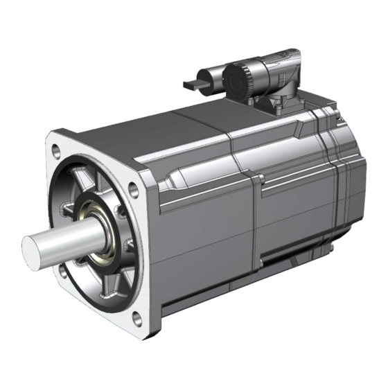
Description of the motors Highlights and benefits Overview The SIMOTICS S-1FK2 servo motors are compact and highly dynamic synchronous motors for a wide range of uses in an industrial environment. They are characterized by high power density, degree of protection and overload capability. The motors are designed for operation without external cooling and the heat is dissipated through the motor surface. -
Page 22: Motors Used For The Intended Purpose
If you wish to use special versions and design variants whose specifications vary from the motors described in this document, then contact your local Siemens office. If you have any questions regarding the intended usage, please contact your local Siemens office. -
Page 23: Technical Features And Ambient Conditions
Description of the motors 2.3 Technical features and ambient conditions Technical features and ambient conditions 2.3.1 Directives and standards Standards that are complied with The motors of the type series SIMOTICS S, SIMOTICS M, SIMOTICS L, SIMOTICS T, SIMOTICS A, called "SIMOTICS motor series" below, fulfill the requirements of the following directives and standards: ●... - Page 24 Quality systems Siemens AG employs a quality management system that meets the requirements of ISO 9001 and ISO 14001. Certificates for SIMOTICS motors can be downloaded from the Internet at the following link: Certificates for SIMOTICS motors (https://support.industry.siemens.com/cs/ww/de/ps/13347/cert)
-
Page 25: Technical Features
Description of the motors 2.3 Technical features and ambient conditions 2.3.2 Technical features Property Version Type of motor Permanent-magnet synchronous motor Degree of protection according to IP64, optionally IP65 EN 60034-5 (IEC 60034-5) Cooling acc. to EN 60034-6 Natural cooling (IC410) Type of construction according to IM B5 (IM V1, IM V3) EN 60034-7 (IEC 60034-7) -
Page 26: Torque Overview
Description of the motors 2.3 Technical features and ambient conditions 2.3.3 Torque overview 1FK2 High Dynamic 3 AC 380 ... 480 V Figure 2-2 Static torques 1FK210❑ 1FK2 Compact 3 AC 380 ... 480 V Figure 2-3 Static torques 1FK22❑❑ 1FK2 High Inertia 3 AC 380 ... -
Page 27: Environmental Conditions
Description of the motors 2.3 Technical features and ambient conditions 2.3.4 Environmental conditions You can classify the environmental conditions for stationary use at weather-protected locations according to the standard DIN EN 60721-3-3. With the exception of environmental influences "Low air temperature", "Low air pressure", and "Condensation", the motor complies with climate class 3K4. -
Page 28: Derating Factors
Description of the motors 2.4 Derating factors Derating factors The specified characteristic curves in Chapter "Data sheets and characteristics (Page 72)" are based on ambient temperature of 40 °C and an installation altitude of 1000 m above sea level. With ambient temperatures > 40 °C or installation altitudes > 1000 m above sea level, the permissible S1-characteristic must be reduced in speed and torque: Table 2- 2 Derating of speed and torque depending on the installation altitude and ambient temper-... - Page 29 Description of the motors 2.5 Selection based on the article number You can find possible combinations in the relevant catalog. Please note that not every theoretical combination is possible. Description Position of the article number 10 11 12 - 13 14 15 16 SIMOTICS S-1FK2 synchronous servomotors Inertia High Dynamic...
-
Page 30: Rating Plate Data
Description of the motors 2.6 Rating plate data Rating plate data The rating plate contains the article number and the technical data of the motor. Figure 2-6 1FK2 rating plate 1 Article number 12 Degree of protection 2 ID No., serial number 13 Rated current 3 Additional options specified as a supple- 14 Cooling mode according to EN 60034-6... -
Page 31: Mechanical Properties
Mechanical properties Cooling The 1FK2 is a non-ventilated motor. To ensure sufficient heat dissipation when installed, the motor requires a minimum clearance of 100 mm from adjacent components on three sides. ● Maintain theses clearances irrespective of the following mounting variants. Non-thermally insulated mounting Some of the motor power loss is dissipated through the flange when the motor is connected to the mounting surface. -
Page 32: Degree Of Protection
Mechanical properties 3.2 Degree of protection Thermal motor protection The converter monitors the motor temperature based on a thermal motor model and issues the alarm "Motor overtemperature" before the maximum temperature is reached. When the motor exceeds the maximum temperature, the converter switches off the motor with the error message "Motor overtemperature". -
Page 33: Types Of Construction
Mechanical properties 3.3 Types of construction Types of construction Table 3- 1 Designation of types of construction (acc. to IEC 60034-7) Designation Representation Description IM B5 Standard IM V1 The motors can be used in types of construction IM V1 and IM V3 without having to order anything special. -
Page 34: Radial And Axial Forces
Mechanical properties 3.6 Radial and axial forces Radial and axial forces 3.6.1 Axial forces When using, for example, helical toothed wheels as drive element, in addition to the radial force, there is also an axial force on the motor bearings. The following axial forces on the shaft extension are permitted. - Page 35 Mechanical properties 3.6 Radial and axial forces Point of application of the radial force at the shaft extension Distance between where the radial force is applied and the flange in mm Figure 3-1 Force application point at the DE (A side) The following diagrams indicate the maximum permissible radial force for the corresponding motor shaft height.
- Page 36 Mechanical properties 3.6 Radial and axial forces Radial force diagram 1FK2x04 Figure 3-3 Maximum permissible radial force at a distance x from the flange for a nominal bearing lifetime of 25000 h Radial force diagram 1FK2105 Figure 3-4 Maximum permissible radial force at a distance x from the flange for a nominal bearing lifetime of 25000 h 1FK2 synchronous motors for SINAMICS S120...
- Page 37 Mechanical properties 3.6 Radial and axial forces Radial force diagram 1FK2205 Figure 3-5 Maximum permissible radial force at a distance x from the flange for a nominal bearing lifetime of 25000 h Radial force diagram 1FK2x06 Figure 3-6 Maximum permissible radial force at a distance x from the flange for a nominal bearing lifetime of 25000 h 1FK2 synchronous motors for SINAMICS S120...
- Page 38 Mechanical properties 3.6 Radial and axial forces Radial force diagram 1FK2x08 Figure 3-7 Maximum permissible radial force at a distance x from the flange for a nominal bearing lifetime of 25000 h Radial force diagram 1FK2210 Figure 3-8 Maximum permissible radial force at a distance x from the flange for a nominal bearing lifetime of 25000 h 1FK2 synchronous motors for SINAMICS S120...
-
Page 39: Sample Calculation Of The Belt Pre-Tension
Mechanical properties 3.7 Radial eccentricity, concentricity and axial eccentricity 3.6.3 Sample calculation of the belt pre-tension Note Carefully comply with the guidelines provided by the belt manufacturer • Carefully comply with the guidelines provided by the belt manufacture when configuring the motor for radial forces at the shaft extension. - Page 40 Mechanical properties 3.7 Radial eccentricity, concentricity and axial eccentricity ① Motor ② Motor shaft ③ Dial gauge Figure 3-9 Checking the radial eccentricity Table 3- 4 Concentricity and axial eccentricity tolerance of the flange surface to the shaft axis (re- ferred to the centering diameter of the mounting flange) Motor Standard (Normal class)
-
Page 41: Balancing
Mechanical properties 3.8 Balancing Balancing The motors are balanced according to EN 60034-14. Motors with feather key in the shaft are half-key balanced. A mass equalization for the protruding half key must be taken into account for the output elements. Vibrational behavior Vibration severity grade Motors with a keyway are balanced with a half feather key by the manufacturer. - Page 42 Mechanical properties 3.9 Vibrational behavior Vibration response Comply with the vibration values in the following table to ensure perfect functioning of the motor and a long service life. Table 3- 5 Vibration values Motor Vibration velocity Vibration acceleration Vibration acceleration peak peak ISO 10816...
-
Page 43: Noise Emission
Mechanical properties 3.10 Noise emission 3.10 Noise emission When operated in the speed range 0 to rated speed, 1FK2 motors can reach the following measuring surface sound pressure level Table 3- 6 Sound pressure level Cooling method Motor Measuring surface sound pressure level Naturally cooled 1FK2❑03 55 dB(A) + 3 dB tolerance... -
Page 44: Service And Inspection Intervals
Replace the motor. For motors 1FK2❑06 ... 1FK2❑10: Replace the motor bearing and the encoder. Maintenance and repair of the motor can be performed by Siemens Service Centers throughout the world. Consult your Siemens representative if you require this service. -
Page 45: Motor Components And Options
Motor components and options Motor components 4.1.1 Encoder Motors with DRIVE-CLiQ interface are designed to operate with the SINAMICS converter system. Signal transmission to the converter is performed digitally. The motors have an electronic rating plate that simplifies commissioning and diagnostics. The motor and encoder system are automatically identified and all motor parameters are automatically set. -
Page 46: Options
Motor components and options 4.2 Options Options 4.2.1 Holding brake 4.2.1.1 Type of holding brake The type of holding brake installed depends on the size of the motor. Type of the holding brake Spring-loaded brake Permanent-magnet brake installed in the motors 1FK2❑03 ... - Page 47 Motor components and options 4.2 Options ● A limited number of Emergency Stop operations is permissible. WARNING Unpredictable movements of the machine or system because of inadequate braking performance If you use the holding brake incorrectly, e.g. as an operating brake or you ignore the permissible operating energy of the brake, then the brake will be subject to excessive and impermissible wear.
-
Page 48: Technical Specifications
Motor components and options 4.2 Options 4.2.1.2 Technical specifications The following table contains technical specifications of the holding brakes: Note The following specifications apply to control with 24 V DC. Motor Holding Dyn. braking Rated Opening Closing time Maximum Total operat- torque torque current... - Page 49 Motor components and options 4.2 Options Holding torque M The holding torque M is the highest permissible torque for the closed brake in steady-state operation without slip (holding function when motor is at standstill). The data applies for the state at operating temperature (120 °C). Dynamic braking torque M The dynamic braking torque M is the smallest mean dynamic braking torque that can occur...
- Page 50 Motor components and options 4.2 Options 1FK2 synchronous motors for SINAMICS S120 Configuration Manual, 06/2019, A5E46927724B AB...
-
Page 51: Configuration
● Installation information of the drive and control components ● Energy considerations of the configured drive systems You can find additional information that you can download in the Internet at SIZER (https://support.industry.siemens.com/cs/document/54992004/sizer-for-siemens- drives?dti=0&pnid=13434&lc=en-WW). 1FK2 synchronous motors for SINAMICS S120 Configuration Manual, 06/2019, A5E46927724B AB... -
Page 52: Startdrive Commissioning Tool
TIA Portal benefits of a common working environment for PLC, HMI, and drives. The SINAMICS Startdrive commissioning tool is available free on the Internet at Startdrive (https://w3.siemens.com/mcms/mc-solutions/en/engineering- software/startdrive/Pages/startdrive.aspx). Startdrive can also be ordered directly as a DVD:... - Page 53 Configuration 5.2 Configuring procedure General configuring procedure The function description of the machine provides the basis for configuration. The components are selected according to physical interdependencies and the selection process is usually carried out in the following sequence of steps: Table 5- 2 Configuring sequence Step...
-
Page 54: Clarify The Drive Type
Configuration 5.2 Configuring procedure 5.2.1 Clarify the drive type Select the motor on the basis of the required torque (load torque), which is defined by the application, e.g. traveling drives, hoisting drives, test stands, centrifuges, paper and rolling mill drives, feed drives or main spindle drives. Gearboxes to convert motion or to adapt the motor speed and motor torque to the load conditions must also be taken into account when selecting the motor. -
Page 55: Define The Load Case, Calculate The Maximum Load Torque And Determine The Motor
Configuration 5.2 Configuring procedure 5.2.3 Define the load case, calculate the maximum load torque and determine the motor The motors are defined bases on the motor type-specific limiting characteristic curves. The limiting characteristic curves describe the torque or power curve over the speed. The limiting characteristic curves take the limits of the motor into account on the basis of the DC link voltage. - Page 56 Configuration 5.2 Configuring procedure Duty cycles with constant ON duration For duty cycles with constant ON duration, there are specific requirements for the torque characteristic curve as a function of the speed, for example: M = constant, M ~ n , M ~ n or P = constant.
- Page 57 Configuration 5.2 Configuring procedure Free duty cycle A free duty cycle defines the curve of the motor speed and the torque over time. Speed Cycle time Torque Δt Time interval Time Figure 5-4 Example of free duty cycle Procedure Determine the required motor torque as follows: 1.
- Page 58 Configuration 5.2 Configuring procedure The following formulas can be used for duty cycles outside the field weakening range. For the motor torque in a time slice Δ the following applies: The motor speed is: The effective torque is obtained as follows: The average motor speed is calculated as follows: Motor moment of inertia Gearbox moment of inertia...
- Page 59 Configuration 5.2 Configuring procedure The effective torque M must lie below the S1 characteristic. The maximum torque M is produced during the acceleration operation. M must lie below the voltage limiting characteristic curve. In summary, the motor is configured as follows: M_max Curve of the maximum torque...
-
Page 60: Output Coupling
Configuration 5.3 Output coupling Output coupling NOTICE Motor damage caused by rotating forces Output couplings, especially stiff metal bellows-type couplings can exercise rotating forces on the shaft. These forces can result in bearing motion and in turn damage the motor. •... - Page 61 Configuration 5.4 Braking resistor (armature short-circuit braking) NOTICE Destruction of the converter as the armature short-circuit contactor incorrectly switches Incorrect switching of the armature short-circuiting contactor can erode the contactor contacts and destroy the converter. • Program the converter so that pulses are first canceled and this is actually implemented before an armature short-circuit contactor is closed or opened.
-
Page 62: Dimensioning Of The Construction Of Braking Resistors
Configuration 5.4 Braking resistor (armature short-circuit braking) 5.4.2 Dimensioning of the construction of braking resistors Rating NOTICE Destruction of the braking resistors Braking from the rated speed is not permitted any more frequently than every 2 minutes; otherwise the resistors will be destroyed. •... -
Page 63: Dimensioning Of Braking Resistors
Configuration 5.4 Braking resistor (armature short-circuit braking) Armature short-circuit braking with external braking resistor without external braking resistor = braking torque = rms braking current Br rms = average braking torque = run-out time Br rms = optimum braking torque n = speed Br opt = braking current... - Page 64 Configuration 5.4 Braking resistor (armature short-circuit braking) The data in the following tables is calculated for rated values according to the data sheet. The variance during production as well as iron saturation have not been taken into account here. Higher currents and torques than those calculated can occur as a result of the saturation.
-
Page 65: Technical Data And Characteristics
Technical data and characteristics Explanations Permissible operating range The permissible operating range is limited by thermal, mechanical, and electromagnetic boundaries. The data in this documentation is valid for self-cooled motors up to an ambient temperature of 40 °C. The temperature rise of the motor is caused by the losses generated in the motor (current- dependent losses, no-load losses, friction losses). - Page 66 Technical data and characteristics 6.1 Explanations S1 characteristic ① The S1 characteristic shows the limits of the permissible temperature range for continuous operation according to the specified heat class of the motor. NOTICE Motor damage due to overheating Continuous operation in the area above the S1 characteristic results in motor overheating and subsequent damage.
- Page 67 Technical data and characteristics 6.1 Explanations The torque-speed diagrams for different converter output voltages are assigned to each data sheet. Table 6- 1 Converter output voltages Drive system Infeed module Line voltage DC link voltage Output voltage line DC LINK SINAMICS S120 400 V 600 V...
-
Page 68: Motor Overview/Motor Module Assignment/Power Cables
Technical data and characteristics 6.2 Motor overview/Motor Module assignment/power cables Note The voltage limit characteristic of a motor with 6000 rpm rated speed is far above that of the same motor type with 2000 rpm. However, for the same torque, this motor requires a significantly higher current. - Page 69 Technical data and characteristics 6.2 Motor overview/Motor Module assignment/power cables SINAMICS S120 Booksize, DC link voltages 510 V DC to 720 V DC, line voltages 3 AC 380 V to 480 V You can find the suitable SINAMICS Motor Modules in the following tables. Motor data Combination with Motor Module SINAMICS S120 Booksize C/D type Article number...
- Page 70 Technical data and characteristics 6.2 Motor overview/Motor Module assignment/power cables Motor data Combination with Motor Module SINAMICS S120 Booksize C/D type Article number Moment of Static / max. Static / max. torque in Article number for Rated / max. current inertia torque combination with S120...
- Page 71 Technical data and characteristics 6.2 Motor overview/Motor Module assignment/power cables Motor data Combination with Motor Module SINAMICS S120 Booksize Compact Article number Moment of Static / max. Static / max. torque in Article number for Rated / max. current inertia torque combination with S120 S120 Booksize...
- Page 72 Technical data and characteristics 6.2 Motor overview/Motor Module assignment/power cables SINAMICS S120 Combi Power Module, DC link voltage 510 V DC to 720 V DC, line voltage 3 AC 380 V to 480 V You can find the suitable SINAMICS Power Modules in the following table. Motor data Combination with Power Modules SINAMICS S120 Combi Article number...
- Page 73 Cable with brake cores (can also be used for motors without brake) Length code ..Additional information on the length code is available in Chapter "MOTION-CONNECT connection systems" of Catalog NC 82 (https://support.industry.siemens.com/cs/ww/en/view/109746977). 1FK2 synchronous motors for SINAMICS S120 Configuration Manual, 06/2019, A5E46927724B AB...
-
Page 74: Data Sheets And Characteristics
Technical data and characteristics 6.3 Data sheets and characteristics Data sheets and characteristics 6.3.1 High Dynamic 6.3.1.1 1FK2104-4AF Three-phase servo motor 1FK2104-4AF Technical specifications in S120 system Symbol Unit Value Static torque 1.27 Stall current 1.19 Maximum permissible speed (at converter) 7200 max Inv Maximum torque... -
Page 75: 1Fk2104-5Af
Technical data and characteristics 6.3 Data sheets and characteristics 6.3.1.2 1FK2104-5AF Three-phase servo motor 1FK2104-5AF Technical specifications in S120 system Symbol Unit Value Static torque Stall current Maximum permissible speed (at converter) 6700 max Inv Maximum torque Maximum current Thermal time constant Moment of inertia kg cm 0.56... -
Page 76: 1Fk2104-6Af
Technical data and characteristics 6.3 Data sheets and characteristics 6.3.1.3 1FK2104-6AF Three-phase servo motor 1FK2104-6AF Technical specifications in S120 system Symbol Unit Value Static torque Stall current Maximum permissible speed (at converter) 7200 max Inv Maximum torque Maximum current 10.9 Thermal time constant Moment of inertia kg cm... -
Page 77: 1Fk2105-4Af
Technical data and characteristics 6.3 Data sheets and characteristics 6.3.1.4 1FK2105-4AF Three-phase servo motor 1FK2105-4AF Technical specifications in S120 system Symbol Unit Value Static torque Stall current 4.65 Maximum permissible speed (at converter) 6000 max Inv Maximum torque Maximum current Thermal time constant Moment of inertia kg cm... -
Page 78: 1Fk2105-6Af
Technical data and characteristics 6.3 Data sheets and characteristics 6.3.1.5 1FK2105-6AF Three-phase servo motor 1FK2105-6AF Technical specifications in S120 system Symbol Unit Value Static torque Stall current Maximum permissible speed (at converter) 6000 max Inv Maximum torque Maximum current Thermal time constant Moment of inertia kg cm 2.65... -
Page 79: Compact
Technical data and characteristics 6.3 Data sheets and characteristics 6.3.2 Compact 6.3.2.1 1FK2204-5AF Three-phase servo motor 1FK2204-5AF Technical specifications in S120 system Symbol Unit Value Static torque Stall current 2.25 Maximum permissible speed (at converter) 7500 max Inv Maximum torque Maximum current Thermal time constant Moment of inertia... -
Page 80: 1Fk2204-6Af
Technical data and characteristics 6.3 Data sheets and characteristics 6.3.2.2 1FK2204-6AF Three-phase servo motor 1FK2204-6AF Technical specifications in S120 system Symbol Unit Value Static torque Stall current Maximum permissible speed (at converter) 7600 max Inv Maximum torque Maximum current Thermal time constant Moment of inertia kg cm 1.61... -
Page 81: 1Fk2205-2Af
Technical data and characteristics 6.3 Data sheets and characteristics 6.3.2.3 1FK2205-2AF Three-phase servo motor 1FK2205-2AF Technical specifications in S120 system Symbol Unit Value Static torque Stall current Maximum permissible speed (at converter) 6000 max Inv Maximum torque 10.8 Maximum current Thermal time constant Moment of inertia kg cm... -
Page 82: 1Fk2205-4Af
Technical data and characteristics 6.3 Data sheets and characteristics 6.3.2.4 1FK2205-4AF Three-phase servo motor 1FK2205-4AF Technical specifications in S120 system Symbol Unit Value Static torque Stall current Maximum permissible speed (at converter) 6000 max Inv Maximum torque Maximum current 15.1 Thermal time constant Moment of inertia kg cm... -
Page 83: 1Fk2206-2Af
Technical data and characteristics 6.3 Data sheets and characteristics 6.3.2.5 1FK2206-2AF Three-phase servo motor 1FK2206-2AF Technical specifications in S120 system Symbol Unit Value Static torque Stall current Maximum permissible speed (at converter) 6000 max Inv Maximum torque Maximum current 17.8 Thermal time constant Moment of inertia kg cm... -
Page 84: 1Fk2206-4Af
Technical data and characteristics 6.3 Data sheets and characteristics 6.3.2.6 1FK2206-4AF Three-phase servo motor 1FK2206-4AF Technical specifications in S120 system Symbol Unit Value Static torque Stall current Maximum permissible speed (at converter) 5800 max Inv Maximum torque Maximum current 29.5 Thermal time constant Moment of inertia kg cm... -
Page 85: 1Fk2208-3Ac
Technical data and characteristics 6.3 Data sheets and characteristics 6.3.2.7 1FK2208-3AC Three-phase servo motor 1FK2208-3AC Technical specifications in S120 system Symbol Unit Value Static torque Stall current Maximum permissible speed (at converter) 4100 max Inv Maximum torque Maximum current 29.5 Thermal time constant Moment of inertia kg cm... -
Page 86: 1Fk2208-4Ac
Technical data and characteristics 6.3 Data sheets and characteristics 6.3.2.8 1FK2208-4AC Three-phase servo motor 1FK2208-4AC Technical specifications in S120 system Symbol Unit Value Static torque Stall current 11.7 Maximum permissible speed (at converter) 4600 max Inv Maximum torque Maximum current 43.5 Thermal time constant Moment of inertia... -
Page 87: 1Fk2208-5Ac
Technical data and characteristics 6.3 Data sheets and characteristics 6.3.2.9 1FK2208-5AC Three-phase servo motor 1FK2208-5AC Technical specifications in S120 system Symbol Unit Value Static torque Stall current 14.6 Maximum permissible speed (at converter) 4700 max Inv Maximum torque Maximum current 51.5 Thermal time constant Moment of inertia... -
Page 88: 1Fk2210-3Ac
Technical data and characteristics 6.3 Data sheets and characteristics 6.3.2.10 1FK2210-3AC Three-phase servo motor 1FK2210-3AC Technical specifications in S120 system Symbol Unit Value Static torque Stall current Maximum permissible speed (at converter) 4400 max Inv Maximum torque Maximum current Thermal time constant Moment of inertia kg cm 88.8... -
Page 89: 1Fk2210-4Ac
Technical data and characteristics 6.3 Data sheets and characteristics 6.3.2.11 1FK2210-4AC Three-phase servo motor 1FK2210-4AC Technical specifications in S120 system Symbol Unit Value Static torque Stall current Maximum permissible speed (at converter) 3300 max Inv Maximum torque Maximum current Thermal time constant Moment of inertia kg cm Moment of inertia (with brake) -
Page 90: 1Fk2210-5Ac
Technical data and characteristics 6.3 Data sheets and characteristics 6.3.2.12 1FK2210-5AC Three-phase servo motor 1FK2210-5AC Technical specifications in S120 system Symbol Unit Value Static torque Stall current 22.5 Maximum permissible speed (at converter) 4000 max Inv Maximum torque Maximum current Thermal time constant Moment of inertia kg cm... -
Page 91: High Inertia
Technical data and characteristics 6.3 Data sheets and characteristics 6.3.3 High Inertia 6.3.3.1 1FK2306-2AC Three-phase servo motor 1FK2306-2AC Technical specifications in S120 system Symbol Unit Value Static torque Stall current Maximum permissible speed (at converter) 4250 max Inv Maximum torque Maximum current 10.3 Thermal time constant... -
Page 92: 1Fk2306-4Ac
Technical data and characteristics 6.3 Data sheets and characteristics 6.3.3.2 1FK2306-4AC Three-phase servo motor 1FK2306-4AC Technical specifications in S120 system Symbol Unit Value Static torque Stall current Maximum permissible speed (at converter) 3300 max Inv Maximum torque Maximum current Thermal time constant Moment of inertia kg cm 29.8... -
Page 93: 1Fk2308-3Ab
Technical data and characteristics 6.3 Data sheets and characteristics 6.3.3.3 1FK2308-3AB Three-phase servo motor 1FK2308-3AB Technical specifications in S120 system Symbol Unit Value Static torque Stall current Maximum permissible speed (at converter) 3000 max Inv Maximum torque Maximum current 20.5 Thermal time constant Moment of inertia kg cm... -
Page 94: 1Fk2308-4Ab
Technical data and characteristics 6.3 Data sheets and characteristics 6.3.3.4 1FK2308-4AB Three-phase servo motor 1FK2308-4AB Technical specifications in S120 system Symbol Unit Value Static torque Stall current Maximum permissible speed (at converter) 3000 max Inv Maximum torque Maximum current Thermal time constant Moment of inertia kg cm 69.1... -
Page 95: Preparation For Use
Preparation for use Transporting Note Comply with the local national regulations for the transportation of motors. ● Use suitable load suspension devices when transporting and installing the motor. ● Do not lift the motor by the connector. ● Transport the motor carefully. Lifting and transporting with lifting slings You can lift and transport the motor using lifting slings. - Page 96 Preparation for use 7.1 Transporting Lifting and transporting the motor with eyebolts For the 1FK2☐10 motors, you can use eyebolts and a lifting beam for lifting and transporting. WARNING Incorrect or unused lifting points Due to incorrect or unused lifting points, the motor can fall and cause death, severe injury and/or damage to property.
- Page 97 Preparation for use 7.1 Transporting Procedure 1. Screw the lifting eyes (eyebolts) in at appropriate locations for the orientation of the motor during transportation. 2. Hook the beam into the lifting eyes (eyebolts). Figure 7-2 Transporting the motor with a beam (example) 3.
-
Page 98: Storage
Preparation for use 7.2 Storage Storage Note If possible, store the motor in its original packaging. Preserve the free shaft extensions, sealing elements, and flange surfaces with a protective coating. NOTICE Seizure damage to bearings If the motors are stored incorrectly, bearing seizure damage can occur, e.g. brinelling, as a result of vibration. - Page 99 Preparation for use 7.2 Storage Long-term storage Note Storage time up to two years The storage time affects the properties of the roller bearing grease. • Store the motor for up to two years at -15° C to 55° C. If you intend to place the motor in storage for longer than six months, you must ensure that the storage area satisfies the following conditions.
- Page 100 Preparation for use 7.2 Storage 1FK2 synchronous motors for SINAMICS S120 Configuration Manual, 06/2019, A5E46927724B AB...
-
Page 101: Electrical Connection
Electrical connection Permissible line system types In combination with the drive system, the motors are generally approved for operation on TN and TT systems with grounded neutral and on IT systems. In operation on IT systems, the occurrence of a first fault between an active part and ground must be signaled by a monitoring device. -
Page 102: System Integration
● Adapt the connecting cables to the type of use and the voltages and currents that occur. ● Use prefabricated cables from SIEMENS (not in the scope of delivery). These cables reduce installation costs and increase operational reliability (see the Product Information). - Page 103 Electrical connection 8.3 System integration Current-carrying capacity for power and signal cables The current-carrying capacity of PVC/PUR-insulated copper cables is specified for routing types B1, B2 and C under continuous operating conditions in the table with reference to an ambient air temperature of 40° C. For other ambient temperatures, the values must be corrected by the factors from the "Derating factors"...
-
Page 104: Rotating The Connector On The Motor
Electrical connection 8.3 System integration 8.3.1.2 Rotating the connector on the motor You can rotate power connectors and signal connectors within a limited range of angles. Use a suitable socket connector to rotate the angle plug. Unscrew and open the socket connector completely to avoid damaging the pin contacts. Note Rotating the connectors •... -
Page 105: Power Connection
Electrical connection 8.3 System integration ② Table 8- 4 Rotation range of the signal connector Motor Connector size of Angle β Angle β' Drawing the signal connect- ② 1FK2❑03 See table "Rotation range of the power connector" 1FK2❑04 1FK2❑05 1FK2❑06 1FK2❑08 1FK2❑10 Table 8- 5... -
Page 106: Signal Connection
(Page 102)" 8.3.4 Connecting to a converter 8.3.4.1 Selecting and connecting the cables ● Use prefabricated MOTION-CONNECT cables from SIEMENS or shielded connecting cables. ● The prefabricated MOTION-CONNECT cables reduce installation costs and increase the operational reliability Note The cable shielding, made up of as many strands as possible, must have a high electrical conductivity. - Page 107 Electrical connection 8.3 System integration Connection diagram for connection of the 1FK2 motor to the S120 Power Module and Motor Module Booksize and Compact with a MOTION-CONNECT cable For connector size M17 ① SPEED-CONNECT connector, size M17 ② Terminal for the cable shield ③...
- Page 108 Electrical connection 8.3 System integration For connector size M23 ① SPEED-CONNECT connector, size M23 ② Terminal for the cable shield ③ Cable shield ④ Connection diagram U; V; W = power cables, 1.5 mm , each cable with separate shielding BD1+ and BD2- = brake cable without lettering, 1.5 mm , shielded together PE = protective conductor...
- Page 109 Electrical connection 8.3 System integration For connector size M40 ① SPEED-CONNECT connector, size M40 ② Terminal for the cable shield ③ Cable shield ④ Connection diagram U; V; W = power cables, 1.5 mm , each cable with separate shielding BD1+ and BD2- = brake cable without lettering, 1.5 mm , shielded together PE = protective conductor...
-
Page 110: Handling The Quick-Action Locking
Electrical connection 8.3 System integration Connection diagram for connection of the signal line for motor 1FK2 on the S120 The connection is made on a signal line with connector M17, 10-pin and RJ45 connector ① ④ M17 round connector, 10-pin Pin assignment of M17 round connector, 10- ②... - Page 111 Electrical connection 8.3 System integration Establishing a SPEED-CONNECT connection Procedure Note • Only tighten the connector by hand. • Do not use any wrenches or similar tools. 1. Ensure that the union nut of the SPEED-CONNECT connector is rotated to the end stop in the direction of the "open"...
-
Page 112: Routing Cables In A Damp Environment
Electrical connection 8.3 System integration Releasing a SPEED-CONNECT connection Procedure 1. Turn the union nut of the SPEED-CONNECT connector in the direction of "open" to the end stop. The triangles on the top of the connectors must be opposite one another. 2. -
Page 113: Assembly Drawings/Dimension Sheets
Assembly drawings/dimension sheets Dimension drawing 1FK2x03 and 1FK2x04 The motor has the following dimensions in the following shaft heights: ① Example for degree of protection IP65 (with shaft sealing ring), for plain shaft and shaft with feather key available, not for shaft extension 11(k6) x 23 ②... - Page 114 Assembly drawings/dimension sheets 9.1 Dimension drawing 1FK2x03 and 1FK2x04 Motor Motor length Motor length up to the con- Size of the connector Height of the connect- nector or for Without With brake Without With brake Power Signals Power Signals brake brake k / mm k1 / mm...
-
Page 115: Dimension Drawing 1Fk2X05
Assembly drawings/dimension sheets 9.2 Dimension drawing 1FK2x05 ... 1FK2x10 Dimension drawing 1FK2x05 ... 1FK2x10 The motor has the following dimensions in the following shaft heights: ① Example for shaft extension with feather key, available for degrees of protection IP64 and IP65 Motor Flange width Diameter of the... - Page 116 You will find further dimensions in the dimension drawings in the relevant catalog. Current dimension drawings are provided in the DT CONFIGURATOR or in Chapter "SIMOTICS Servomotors" in Catalog NC 82 (https://support.industry.siemens.com/cs/ww/en/view/109746977) as print version or online. 1FK2 synchronous motors for SINAMICS S120 Configuration Manual, 06/2019, A5E46927724B AB...
- Page 117 Recency of dimension drawings Note Changing motor dimensions Siemens AG reserves the right to change the dimensions of the motors as part of mechanical design improvements without prior notice. This means that dimension drawings can become out of date. 1FK2 synchronous motors for SINAMICS S120...
- Page 118 Assembly drawings/dimension sheets 9.2 Dimension drawing 1FK2x05 ... 1FK2x10 1FK2 synchronous motors for SINAMICS S120 Configuration Manual, 06/2019, A5E46927724B AB...
-
Page 119: Glossary
Glossary Rated torque M Thermally permissible continuous torque in S1 duty at the rated motor speed. Rated speed n The characteristic speed range for the motor is defined in the speed-torque diagram by the rated speed. Rated current I RMS motor phase current for generating the particular rated torque. Specification of the RMS value of a sinusoidal current. - Page 120 Glossary Non-drive end = Non-drive end of the motor Static torque M Thermal torque limit when the motor is at a standstill corresponding to the motor thermal class. M is always ≥ the rated torque M Stall current I Motor phase current to generate the particular stall torque (M •...
-
Page 121: Index
Radial force loading, 33 Belt pretension, 37 Rating plate, 28 Braking resistors, 58 RoHS, 22 Certificates Siemens Service Center, 4 EAC, 22 Smooth running, 37 EC Declaration of Conformity, 22 Sound pressure level, 41 UL and cUL, 22 Concentricity, 38... - Page 122 Siemens AG Digital Industries Motion Control Postfach 31 80 91050 ERLANGEN Germany Scan the QR code for additional informati- on about SIMOTICS.