Siemens SENTRON PAC4200 Manual
Power monitoring device
Hide thumbs
Also See for SENTRON PAC4200:
- Manual (252 pages) ,
- Operating instructions manual (32 pages)

Related Manuals for Siemens SENTRON PAC4200


Summary of Contents for Siemens SENTRON PAC4200
- Page 1 PAC4200...
- Page 2 Introduction Description SENTRON Installation Connection Power Monitoring Device PAC4200 Commissioning Operation System Manual Parameterizing Service and maintenance Technical data Dimensional drawings Appendix List of abbreviations 05/2019 A5E02316180B-05...
- Page 3 Note the following: WARNING Siemens products may only be used for the applications described in the catalog and in the relevant technical documentation. If products and components from other manufacturers are used, these must be recommended or approved by Siemens. Proper transport, storage, installation, assembly, commissioning, operation and maintenance are required to ensure that the products operate safely and without any problems.
-
Page 4: Table Of Contents
Table of contents Introduction ............................. 7 Components of the product ...................... 7 Latest information ........................7 Security information ........................9 Description ............................11 Performance features ......................11 Measuring inputs ........................16 Measured variables ......................... 18 2.3.1 Sliding window demands ......................21 2.3.2 Averaging measured values (aggregation) ................ - Page 5 Table of contents Deinstallation .......................... 51 Connection ............................53 Safety information ........................53 Connections ........................... 55 Connection examples ......................58 Grounding of the Ethernet cable .................... 65 Commissioning ............................. 67 Overview ..........................67 Applying the supply voltage ....................68 Parameterizing the device ..................... 69 5.3.1 First start-up ...........................
- Page 6 Table of contents 7.2.7 Integrated I/Os ........................97 7.2.8 Communication ........................101 7.2.9 Display ..........................103 7.2.10 Advanced ..........................104 Protection against manipulation .................... 111 7.3.1 Introduction ........................... 111 7.3.2 Password protection ......................112 7.3.3 Hardware write protection ..................... 114 7.3.4 Device access control (IP filter) ....................
- Page 7 Table of contents A.2.19 MODBUS standard device identification with the function code 0x2B ........ 212 Comprehensive support from A to Z ..................213 List of abbreviations ..........................215 Abbreviations ........................215 Glossary .............................. 217 Index ..............................219 PAC4200 System Manual, 05/2019, A5E02316180B-05...
-
Page 8: Introduction
Product. The OSS portions of this Product are provided royalty-free and can be used at no charge. If SIEMENS has combined or linked certain components of the Product with/to OSS components licensed under the GNU LGPL version 2 or later as per the definition of the applicable license, and if use of the corresponding object file is not unrestricted ("LGPL... - Page 9 Product or any OSS components contained in it if they are modified or used in any manner not specified by SIEMENS. The license conditions listed below may contain disclaimers that apply between you and the respective licensor.
-
Page 10: Security Information
Siemens’ products and solutions undergo continuous development to make them more secure. Siemens strongly recommends that product updates are applied as soon as they are available and that the latest product versions are used. Use of product versions that are no longer supported, and failure to apply the latest updates may increase customer's exposure to cyber threats. - Page 11 Introduction 1.3 Security information Safety-related symbols on the device Symbol Meaning Risk of electric shock General warning symbol Electrical installation and maintenance by qualified personnel only See also Applying the measuring current (Page 72) Applying the measuring voltage (Page 71) Applying the supply voltage (Page 68) Replacing the battery (Page 123) Password protection (Page 112)
-
Page 12: Description
Description Performance features The SENTRON PAC4200 is a measuring device for measuring the basic electrical variables in low-voltage power distribution. The device is capable of single-phase, two-phase or three- phase measurement and can be used in 2, 3 or 4-wire TN, TT and IT systems. - Page 13 Using optionally available expansion module "I(N), I(DIFF), Analog" (MLFB: 7KM9200- 0AD00-0AA0) Manual 7KM PAC expansion module I(N), I(Diff), analog (https://support.industry.siemens.com/cs/ww/en/view/109746834) Counters and power demand ● A total of 10 energy counters capture reactive energy, apparent energy, and active energy for off-peak and on-peak, import and export.
- Page 14 Description 2.1 Performance features Monitoring functions The SENTRON PAC4200 monitors up to 12 limit values as well as one limit that can be formed by logically combining the other 12 limits. Event display ● Recording up to 4096 events with a time stamp and event-specific information ●...
- Page 15 ● Counter values: Every 5 minutes ● Minimum/maximum values: Every 5 seconds, if present Tariffs SENTRON PAC4200 supports 2 tariffs for the integrated energy counter (on-peak and off- peak). ● Control of tariff switching Switching between off-peak and on-peak can be controlled via the digital input or the communication interfaces.
- Page 16 ● Simple Network Time protocol (SNTP) included Using "Password protection" and "Hardware write protection", you can protect against write access to the device settings of the SENTRON PAC4200. The protection takes effect in case of the following actions: Modify parameters in device. Reset maximum. Reset minimum. Reset counter. Reset device.
-
Page 17: Measuring Inputs
AC measurement only Use the device to measure alternating current only. SENTRON PAC4200 is designed for: ● Measuring current of 1 A or 5 A for connecting current transformers. Each current measuring input can take a continuous load of 10 A. - Page 18 NOTICE Material damage due to incorrect system connection Before connecting SENTRON PAC4200, you must ensure that the local power supply conditions match the specifications on the rating plate. The short code of the connection type must be entered in the device settings at startup. You can find the instructions for parameterizing the connection type in chapter Commissioning (Page 67).
-
Page 19: Measured Variables
Description 2.3 Measured variables Measured variables The total set of representable measured variables is restricted by the method of connecting the device. The availability of the measured variables depends on the type of readout. A measured variable that cannot be indicated due to the connection method is shown on the display by means of a broken line "----". - Page 20 Description 2.3 Measured variables Measured variable Connection type 3P4W 3P3W 3P4WB 3P3WB 1P2W Cos φ L1 ✓ ✓ ✓ ✓ Cos φ L2 ✓ Cos φ L3 ✓ Power factor L1 ✓ Power factor L2 ✓ Power factor L3 ✓ Total power factor ✓...
- Page 21 Description 2.3 Measured variables Measured variable Connection type 3P4W 3P3W 3P4WB 3P3WB 1P2W Harmonic content of the 1st, 2nd, 3rd, ... 64th harmonics for ✓ ✓ ✓ the L2-L3 voltage referred to the fundamental Harmonic content of the 1st, 2nd, 3rd, ... 64th harmonics for ✓...
-
Page 22: Sliding Window Demands
Figure 2-1 Sliding window demand SENTRON PAC4200 supplies sliding window demand values for a large number of measured variables: ● Per phase or as a total value over all phases ● With the maximum and minimum values, and the time stamp of the extreme value The sliding window demand values are represented on the display and can be called via the communication interfaces. -
Page 23: Averaging Measured Values (Aggregation)
For this purpose, instantaneous measured values would need to be read out via the communication interface and stored. Uninterrupted recording requires a high bandwidth, high availability of communication and high storage capacity. The SENTRON PAC4200 provides two internal average value generators which can be parameterized independently of each other. -
Page 24: Load Profile
The load profile records the time history of the electric power and thus documents the distribution of power fluctuations and peaks. SENTRON PAC4200 supports load profile recording according to the "fixed block" or "rolling block" method. With both methods, the load profile is stored in the device and made available at the communication interfaces. - Page 25 Description 2.4 Load profile The Q and Q options that can be set using powerconfig correspond to the reactive power values shown in the power tetrahedron: = Displacement reactive power over fundamental U = Total reactive power cannot be displayed graphically here and can be explained as follows: = Displacement reactive power over fundamental U + harmonic components U As the fundamental component of the voltage is usually high in practice, the following...
- Page 26 Description 2.4 Load profile Load profile recording methods SENTRON PAC4200 supports the following load profile recording methods: ● Fixed block ● Rolling block The default setting is the fixed block method with a demand period length of 15 minutes. Fixed block method The load profile data is calculated and stored at the end of each demand period.
- Page 27 2.4 Load profile Parameterizing the fixed block and rolling block methods SENTRON PAC4200 supports the fixed block method as a special case of the rolling block method. The most important distinguishing feature is the number of subperiods. Number of subperiods: The demand period can be divided into a maximum of five subperiods.
-
Page 28: Historical Load Profile
● The complete load profile memory can be cleared. Storage concept of the load profile memory The memory of SENTRON PAC4200 is designed as a circular buffer. If the maximum available memory is exceeded, the data which has been stored the longest is overwritten by the newest data. -
Page 29: Current Load Profile Data At The Communication Interfaces
Storage capacity of the load profile memory The data volume that occurs when a load profile is recorded depends on the length of the period. SENTRON PAC4200 can record load profile data for the following configuration over a period of 40 days: ● Fixed block: Length of demand period: 15 minutes ●... -
Page 30: Synchronization Of The Load Profile
Response to powering up All load profiles that have already been recorded remain unchanged. SENTRON PAC4200 resets the internal clock if it detects load profiles with a date in the future or a time in the past on powering up. -
Page 31: Additional Information About The Load Profile Data
The last tariff remains valid until the end of the instantaneous period. The new tariff takes effect at the start of the next period. The energy counters of SENTRON PAC4200 are switched to the other tariff at the end of the instantaneous demand period. -
Page 32: Technical Features Of The Network Quality
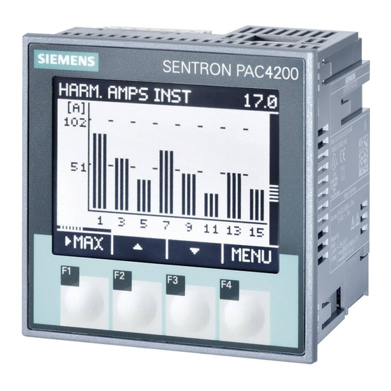
They are integer multiples of a fundamental. The SENTRON PAC4200 can calculate odd (3rd to 63rd) or all (1st to 64th) integer voltage and current harmonics and display them as a bar diagram on the display. - Page 33 It indicates the ratio of the harmonic content to the fundamental in percent. SENTRON PAC4200 measures the THD of the voltage and the THD of the current referred to the fundamental. The instantaneous value, the maximum value and the time stamp of the maximum value are supplied.
-
Page 34: Date And Time
("+1"). Synchronization of clock time The internal clock of the SENTRON PAC4200 can be synchronized with an external time, e.g. using the "Top of minute" pulse, or by means of a synchronization command via the available communication interfaces, or automatically via SNTP (Simple Network Time Protocol). -
Page 35: Limit Values
Description 2.8 Limit values Limit values SENTRON PAC4200 monitors up to 12 limit values as well as one limit that can be formed by logically combining the other 12 limits. Definition of the limit values The number of limit values to be monitored is selectable. The following must be specified for each of the maximum of 12 limit values: ●... -
Page 36: Function Of The Digital Inputs And Outputs
2.9 Function of the digital inputs and outputs Any limit values and the digital inputs of SENTRON PAC4200 can be selected at the inputs of the upstream logic function blocks. The input value is the truth value of the monitored signal: ●... - Page 37 Description 2.9 Function of the digital inputs and outputs ● Limit violation The digital output is switched on by a defined limit violation and remains active for as long as the limit violation persists. ● Synchronization pulse The digital output is switched on for the defined time (synchronization length). Wiring Figure 2-8 Block diagram: Digital outputs...
-
Page 38: Digital Input
Description 2.9 Function of the digital inputs and outputs 2.9.2 Digital input The following functions can be assigned to the digital input: ● Not used The digital input is deactivated. ● Pulse input Edge or pulse counting as required. Data is transferred with the help of weighted pulses or edges, e.g. a parameterizable number of pulses or edges is transferred per kWh. -
Page 39: Ethernet Interface
NTP server. This is practical if the internal clocks of several devices in the same network need to remain synchronized. If the IP address of the NTP server has been configured, the SENTRON PAC4200 only responds to these frames. Furthermore, it can send a request to the server, if necessary. -
Page 40: Slots For Expansion Modules
Description 2.11 Slots for expansion modules 2.11 Slots for expansion modules SENTRON PAC4200 has two slots (MOD1 and MOD2) for installing optionally available expansion modules. Please consult the current catalogs to find out which modules are available for SENTRON PAC4200. -
Page 41: Gateway
Description 2.12 Gateway 2.12 Gateway SENTRON PAC4200 can be used as a gateway. This allows devices (slaves) that are connected to the RS485 expansion module of PAC4200 to be connected to a device over Ethernet (master). Operating principle Data sent by the master to the addressed target device: The higher-level software packages the serial protocol into TCP/IP packets. - Page 42 ● Set the communication parameters for operating the RS485 bus below the gateway. These settings are possible on the display of SENTRON PAC4200 or in the software. You can find information about parameterizing RS 485 in the documentation for the SENTRON PAC RS485 expansion module or under Modbus-IDA (http://www.Modbus-...
-
Page 43: Insertion Openings
Battery to be used: 3 V lithium button cell type: CR2032 Slot for memory card The card slot of the SENTRON PAC4200 has no function. The device does not contain a card reader. Memory cards must not be inserted in the slot. -
Page 44: User-Definable Displays
See also Replacing the battery (Page 123) 2.14 User-definable displays Up to four measurements can be individually configured for SENTRON PAC4200. Four presentational formats can be selected: ● Digital display of two measured variables ● Digital display of four measured variables ●... - Page 45 Description 2.14 User-definable displays Displays for counters Users can define up to 5 displays in conjunction with the SENTRON PAC 4DI/2DO expansion module. Configuring The displays can be configured with the SENTRON powerconfig software. PAC4200 System Manual, 05/2019, A5E02316180B-05...
-
Page 46: Installation
Only operate the device in a secure location. Can cause death, serious injury or property damage. The SENTRON PAC4200 must only be operated in a lockable control cabinet or a lockable room. Ensure only qualified personnel have access to this cabinet or room. - Page 47 Circuit breaker Connect a suitable circuit breaker upstream of SENTRON PAC4200 in order to disconnect the device from the power supply. ● The circuit breaker must be installed close to the device and must be easily accessible for the user.
-
Page 48: Inserting The Battery
Installation 3.2 Inserting the battery Inserting the battery DANGER Hazardous voltage. Will cause death or serious injury. Turn off and lock out all power supplying this equipment before working on this device. For first start-up, use the battery supplied with the device (3 V lithium button cell type: CR2032). -
Page 49: Tools
Installation 3.3 Tools Tools You require the following tools for installation: ● Cutting tool for the panel cutout ● PH2 cal. screwdriver ISO 6789 ● Cable clamp for strain relief on all communication cables if used on the device. Mounting on the switching panel 3.4.1 Mounting dimensions Mounting and clearance dimensions... -
Page 50: Installation Steps
Installation 3.4 Mounting on the switching panel 3.4.2 Installation steps Proceed as follows to install the SENTRON PAC4200 in the switching panel: Procedure Figure 3-3 Installation step A, device with screw terminals Figure 3-4 Installation step A, device with ring lug terminals... - Page 51 Installation 3.4 Mounting on the switching panel Figure 3-5 Installation step B Figure 3-6 Installation step C Figure 3-7 Installation step D PAC4200 System Manual, 05/2019, A5E02316180B-05...
-
Page 52: Deinstallation
Installation 3.5 Deinstallation Deinstallation Make sure the device has been shut down before you begin to deinstall it. Tools You require the following tools to deinstall the device: ● PH2 screwdriver ● Slotted screwdriver Figure 3-8 Deinstallation A, loosening the screw Figure 3-9 Deinstallation B, releasing the locking hooks PAC4200... - Page 53 Installation 3.5 Deinstallation PAC4200 System Manual, 05/2019, A5E02316180B-05...
-
Page 54: Connection
Connection Safety information Instructions DANGER Hazardous voltages! Will cause death, serious injury or property damage. Turn off and lock out all power supplying this equipment before working on this device. DANGER Open transformer circuits will result in electric shock and arc flashover. Will cause death, serious injury or property damage. - Page 55 Connection 4.1 Safety information NOTICE Grounding of current transformers optional The connection of the transformers and thus also the grounding of the transformers on the secondary side must always be carried out according to the applicable regulations. Grounding of the current transformers on the secondary side is not necessary for use in low-voltage switchboards for performing measuring tasks.
-
Page 56: Connections
Connection 4.2 Connections Connections Note Use of devices with ring lug terminals Designed for use in: • NAFTA/USA • Regions in which open terminals are permitted. Terminal labeling Figure 4-1 Terminal labeling, device with screw terminals PAC4200 System Manual, 05/2019, A5E02316180B-05... - Page 57 Connection 4.2 Connections Figure 4-2 Terminal designation, device with ring lug terminals Connection Function ↑k Current I , input ° IL1 l↓ Current I , output ↑k Current I , input ° IL2 l↓ Current I , output ↑k Current I , input °...
- Page 58 Connection 4.2 Connections Connection Function (19) Digital output 0 (20) Battery Battery compartment (21) MOD 1/2 Slot for optional expansion module Grounding Conductive panels and doors on control cabinets must be grounded. The doors of the control cabinet must be connected to the control cabinet using a grounding cable. Reference potential (13) Reference potential terminal...
-
Page 59: Connection Examples
Connection 4.3 Connection examples Protection of the supply voltage and voltage measuring inputs CAUTION Protection of the supply voltage and voltage measuring inputs The fuses in the supply voltage and the voltage measuring inputs are only used for cable protection. Selection of the fuse depends on the supply cable dimensioning. All commercially available fuses and automatic circuit breakers up to 16 A (C) or 20 A (B) can be used. - Page 60 Connection 4.3 Connection examples Connection examples (1) Three-phase measurement, four conductors, unbalanced load, without voltage transformer, with three current transformers Connection type 3P4W The fuses are only used for cable protection. All commercially available fuses and automatic circuit breakers up to 16 A (C) or 20 A (B) can be used.
- Page 61 Connection 4.3 Connection examples (3) Three-phase measurement, four conductors, balanced load, without voltage transformer, with one current transformer Connection type 3P4WB The fuses are only used for cable protection. All commercially available fuses and automatic circuit breakers up to 16 A (C) or 20 A (B) can be used.
- Page 62 Connection 4.3 Connection examples (5) Three-phase measurement, three conductors, unbalanced load, without voltage transformer, with three current transformers Connection type 3P3W The fuses are only used for cable protection. All commercially available fuses and automatic circuit breakers up to 16 A (C) or 20 A (B) can be used.
- Page 63 Connection 4.3 Connection examples (7) Three-phase measurement, three conductors, unbalanced load, without voltage transformer, with two current transformers Connection type 3P3W The fuses are only used for cable protection. All commercially available fuses and automatic circuit breakers up to 16 A (C) or 20 A (B) can be used.
- Page 64 Connection 4.3 Connection examples (9) Three-phase measurement, three conductors, balanced load, without voltage transformer, with one current transformer Connection type 3P3WB The fuses are only used for cable protection. All commercially available fuses and automatic circuit breakers up to 16 A (C) or 20 A (B) can be used.
- Page 65 Connection 4.3 Connection examples (11) Two-phase measurement, three conductors, unbalanced load, without voltage transformer, with two current transformers Connection type 3P4W The fuses are only used for cable protection. All commercially available fuses and automatic circuit breakers up to 16 A (C) or 20 A (B) can be used.
-
Page 66: Grounding Of The Ethernet Cable
Make a shield connection on both sides as described here. Type Ground the Ethernet cable near the SENTRON PAC4200 device. To do this, expose the foil shield of the Ethernet cable. Connect the exposed shield to a suitable grounding point on the control cabinet, preferably a shielding bus. - Page 67 Connection 4.4 Grounding of the Ethernet cable PAC4200 System Manual, 05/2019, A5E02316180B-05...
-
Page 68: Commissioning
6. Check the polarity and the phase assignment of the measuring transducers. Note Checking the connections Incorrect connection can result in malfunctions and failure of the device. Before starting up the SENTRON PAC4200, check that all connections are correct. PAC4200 System Manual, 05/2019, A5E02316180B-05... -
Page 69: Applying The Supply Voltage
Commissioning 5.2 Applying the supply voltage Applying the supply voltage SENTRON PAC4200 can be supplied with: ● A wide-voltage AC/DC power supply ● An extra-low voltage DC power supply A supply voltage is required to operate the device. Refer to the technical data or the rating plate for the type and level of the permissible supply voltage. -
Page 70: Parameterizing The Device
Commissioning 5.3 Parameterizing the device Parameterizing the device To start up the device, you must specify the operating parameters listed below in the device settings: ● Basic parameters The following settings are also useful: ● Language ● Date/time ● Device protection against manipulation 5.3.1 First start-up The language selection only appears:... -
Page 71: Basic Parameters
Commissioning 5.3 Parameterizing the device 5.3.2 Basic parameters Set the basic parameters: ● Connection type ● Voltage – Direct measurement on the system or using voltage transformers – Measuring input voltage in the case of direct measurement on the system –... -
Page 72: Additional Settings
● 400 V phase-to-neutral (max. 347 V for UL) ● 690 V phase-to-phase (max. 600 V for UL) SENTRON PAC4200 with an extra-low voltage power supply is designed for measuring in systems with a rated AC voltage up to: ● 289 V phase-to-neutral ●... -
Page 73: Applying The Measuring Current
Commissioning 5.5 Applying the measuring current Applying the measuring current The device is designed for connection of current transformers with secondary currents of 1 A and 5 A. It is only possible to measure alternating currents. The current measuring inputs can each be loaded with 10 A continuously or with 100 A for 1 second. -
Page 74: Operation
Displays and operator controls Displays and operator controls The front of SENTRON PAC4200 has the following displays and operator controls. Display area: Represents the current measured values, device settings and selection menus. Header area: Specifies the information visible in the display area. -
Page 75: Special Display Elements
Operation 6.1 Device interface 6.1.2 Special display elements Symbol Meaning Selection bar Separating line between start of list/end of list Scroll bar of function key F1 (multiple assignments of key F1) Up arrow: Maximum value • Down arrow: Minimum value •... -
Page 76: Menu-Based Navigation
Operation 6.1 Device interface 6.1.3 Menu-based navigation The menu-based navigation is intuitive and self-explanatory. Only the basic structure of the menu-based navigation will be explained for this reason. The description and function of the individual parameters can be found in chapter Parameterizing (Page 89). The device menu can be subdivided into four menu levels: ●... -
Page 77: Main Menu Level
Operation 6.1 Device interface 6.1.5 Main menu level In this menu level, all available measured variables are listed without measured values. The main menu level also has a "SETTINGS" selection menu item which can be used to configure the device. key returns the device to the measured value level. -
Page 78: Control Keys
Operation 6.1 Device interface 6.1.8 Control keys The device can be operated by means of four keys. The keys are assigned different functions. The functions of the keys depend on the menu level currently in use. Keys Possible assignment Meaning Display the maximum value Display the minimum value Display the sliding window demand... - Page 79 Operation 6.1 Device interface Keys Possible assignment Meaning Scroll up in the selection list Display additional information Scroll to the left. Display the energy export per tariff for a specific period Display the energy import per tariff for a specific period Increment the numerical value by "1"...
-
Page 80: Special Displays
Operation 6.2 Special displays Special displays 6.2.1 Phasor diagram The phasor diagram provides a coherent picture of the actual unbalance values of the fundamental. The graphical representation is assigned a value table. F1 switches between the two representations. Special displays of the phasor diagram The length of graphical axes in the diagram symbolizes the amplitude unbalance. -
Page 81: Measurement Of 1St To 64Th Harmonics For Voltage And Current
They are integer multiples of a fundamental. The SENTRON PAC4200 measures integer voltage and current harmonics and shows the results on the display. It is also possible to read out the data using Modbus command 0xFC20 "Read File Record 0x14". - Page 82 Operation 6.2 Special displays 3. The following harmonic displays are available on the device display: – Harmonic UL-N (display 15.0) – Harmonic UL-L (display 16.0) – Harmonic I (display 17.0) 4. The following additional functions can be called using the F1 key –...
-
Page 83: Events
6.2 Special displays 6.2.3 Events The device reports the occurrence of certain events. These events are listed in the event recording undertaken by SENTRON PAC4200. You can acknowledge acknowledgable events in a popup window on the device. Displaying events Table 6- 1... - Page 84 The current is out of range. CURRENT Make sure the system is mation Measured variable x operating under condi- tions for which SENTRON PAC4200 is approved. It is possible that the measured values are not correctly displayed. Please contact Support. Operating infor-...
- Page 85 Operation 6.2 Special displays Event Event Standard Reason Remedy class warning level LIMIT LOG. OP=1 Operating infor- Information The limit logic operation com- mation plies with the limit value xxxx. TARIFF Operating infor- Information Tariff change to ... mation STATUS DI Operating infor- Information The digital input is activated.
- Page 86 Operation 6.2 Special displays Event Event Standard Reason Remedy class warning level OP.HOURS=0 Operation Information The operating hours counter has been reset. Slot xx interface D ENERGY=0 Operation Information The day energy counter has been reset. Slot xx interface EVENT=0 Operation Information The event recordings have been...
-
Page 87: Supporting Software
6.3.1 SENTRON powermanager Using the SENTRON powermanager energy management software energy data of the SENTRON PAC4200 measuring device can be acquired, monitored, evaluated, displayed and archived. SENTRON powermanager offers the following functions: ● Tree view of the customer's system (project tree) ●... -
Page 88: Sentron Powerconfig
Operation 6.3 Supporting software 6.3.2 SENTRON powerconfig The powerconfig software is the combined commissioning and service tool for communication-capable measuring devices and circuit breakers from the SENTRON family. The PC-based tool facilitates parameterization of the devices, resulting in substantial time savings, particularly when several devices have to be set up. - Page 89 Operation 6.3 Supporting software PAC4200 System Manual, 05/2019, A5E02316180B-05...
-
Page 90: Parameterizing
Parameterizing Introduction Device settings The "Parameterizing" chapter describes the device settings. This includes: ● Adjustment to the physical conditions of use ● Integration into the communication system ● Country-specific settings, ergonomics, device protection It is possible to set the device by means of: ●... -
Page 91: Parameterizing Via The User Interface
7.2.1 Parameterizing via the user interface The SENTRON PAC4200 can be parameterized via the "Settings" menu options. You can find more information on this in chapter Menu-based navigation (Page 75). The device settings are arranged into the following groups. The "SETTINGS" menu shows the choice of groups: ●... -
Page 92: Device Information
Parameterizing 7.2 Parameterizing via the user interface 7.2.2 Device information The device information cannot be modified. PAC4200 Device designation 7KM4212-0BA00-3AA Article number of the device S/N: xxxxxx Serial number of the device D/T: xxxxxx Date code ES: xxx Hardware revision level SW-REV: xxxx Firmware revision level BL-REV: xxxx... - Page 93 Parameterizing 7.2 Parameterizing via the user interface Voltage input Selection Range Factory setting Connection type 3P4W 3P4W • 3 phases, 4 conductors, unbalanced load 3P3W • 3 phases, 3 conductors, unbalanced load 3P4WB • 3 phases, 4 conductors, balanced load 3P3WB •...
- Page 94 Parameterizing 7.2 Parameterizing via the user interface Current input Selection Range Factory setting CT PRIMARY Primary current of the current transformers 50 A 1 A … 99999 A CT SECONDARY Secondary current of the current transformers • • Inverse evaluation of the current flow direction separately for each phase. CURRENT DIREC L1 •...
- Page 95 Parameterizing 7.2 Parameterizing via the user interface Voltage dip/swell Selection Range Factory setting NOM. VOLTAGE Specification of nominal voltage Udin according to IEC 61000-4-30. The 230 V specification refers to the L-N measuring voltage. In 3-wire systems, the specification refers to the L-L measuring voltage. 0 V …...
-
Page 96: Power Demand
Parameterizing 7.2 Parameterizing via the user interface 7.2.5 Power demand Settings for the load profile can be made in the "Power demand" menu item. You can find more information on the load profile in chapter Load profile (Page 23). Selection Range Factory setting SUBPERIOD TIME... - Page 97 Parameterizing 7.2 Parameterizing via the user interface Selection Range Factory setting DATE Current date The date format is defined in the FORMAT field. FORMAT DD.MM.YYYY DD.MM.YYYY • YYYY-MM-DD • MM/DD/YY • TIME HH:MM:SS TIME ZONE Time zone, refers to coordinated universal time (UTC). 00:00 −12:00 …...
-
Page 98: Integrated I/Os
Parameterizing 7.2 Parameterizing via the user interface 7.2.7 Integrated I/Os Device settings for using the digital inputs and outputs. Digital output Selection Range Factory setting DIG.OUTPUT Two digital outputs are available: • • ACTION OFF: Output is deactivated. • DEVICE ON: Output signals that the device is switched •... - Page 99 Parameterizing 7.2 Parameterizing via the user interface Selection Range Factory setting SOURCE Selects the type of cumulated power (active energy or reac- kWh IMPORT tive energy): (only with ENERGY PULSE) kWh IMPORT • kWh EXPORT • kvarh IMPORT • kvarh EXPORT •...
- Page 100 Parameterizing 7.2 Parameterizing via the user interface Digital input Selection Range Factory setting DIG.INPUT Two digital inputs are available: • • ACTION NONE NONE: Input is deactivated. • WRITE PROTECTION: Input is used as write protection. Auxiliary • voltage at input is needed. PULSE INPUT: Counting of input pulses.
- Page 101 Parameterizing 7.2 Parameterizing via the user interface Selection Range Factory setting MODE Counting of pulses or edges. PULSE (only with PULSE INPUT) PULSE: Pulses are counted. • EDGE: Edges are counted. • PULSES PER UNIT Number of pulses that must be received per unit in order for the counter to be incremented by "1".
-
Page 102: Communication
• MODBUS PORT 0 … 65534 IP FILTER CONFIG. Configuration of IP filter. Access rights to the SENTRON PAC4200 are defined in up to 5 tables depending on requirements. The configuration menu is described in the table below. PAC4200 System Manual, 05/2019, A5E02316180B-05... - Page 103 Parameterizing 7.2 Parameterizing via the user interface Selection Range Factory setting IP (table 1-5) Assignment of access rights for specific IP address/addresses. Format: 000.000.000.000 SN (table 1-5) Assignment of access rights for specific subnets. Format: 000.000.000.000 FLAGS (table 1-5) Configuration of access type: Deactivated -MODBUS R (read access only) -MODBUS RW (read and write access)
-
Page 104: Display
Parameterizing 7.2 Parameterizing via the user interface 7.2.9 Display Selection Range Factory setting CONTRAST Contrast of the LC display. 0 … 10 BACKLIGHT LEVEL Intensity of the backlighting of the LC display. 0 … 3 BACKLIGHT DIMMED Intensity of the backlighting of the LC display. Set by the device after the display time until dimmed expires. -
Page 105: Advanced
Parameterizing 7.2 Parameterizing via the user interface 7.2.10 Advanced Write protection Selection Range Factory setting WRITE PROTECTION Write access is not possible when the hardware write protection is activated. ON: Write protection active • OFF: Write protection deactivated • In order to gain write access, the hardware write protection must be deactivated directly on the device. - Page 106 Parameterizing 7.2 Parameterizing via the user interface Limit values Monitoring of up to 12 limit values "LIM0" to "LIM11" and the limit value "LIMIT LOGIC". The limit value "LIMIT LOGIC" can be made up of any combination of the limit values "LIM0" to "LIM11"...
- Page 107 Parameterizing 7.2 Parameterizing via the user interface Selection Range Factory setting HYSTERESIS Threshold buffer. This prolongs the limit violation. 0.0% The hysteresis refers to the disappearance of the limit violation or the point when the level returns below the defined threshold. 0.0% ...
- Page 108 Parameterizing 7.2 Parameterizing via the user interface Limit logic Logical truth value resulting from the combination of up to 12 limit values "LIM0" to "LIM11", taking account of the logical priority rules and allowing logical brackets. Symbol Description OR logic operation: The output value is true if any one of the input values or several input values are true.
- Page 109 Parameterizing 7.2 Parameterizing via the user interface Universal counter The device has two configurable universal counters with the following capabilities: ● Counting at digital inputs or outputs – Limit violations – Status changes ● Energy indications of a connected pulse encoder –...
- Page 110 Parameterizing 7.2 Parameterizing via the user interface Replacing the battery This will start data backup. The SENTRON PAC4200 copies the data from the battery- backed memory into the internal non-volatile memory. The data does not leave the device. The following data is stored: ●...
- Page 111 RESET PULSE COUNTERS Resets the pulse counters. This option is only available if at least one SENTRON PAC 4DI/2DO expansion module is plugged into the SENTRON PAC4200 device. FACTORY SETTINGS Resets all device settings to the default values. • Clears minimum/maximum values.
-
Page 112: Protection Against Manipulation
The expansion modules are not included in the scope of delivery. They can be ordered as options. Protection against manipulation 7.3.1 Introduction The SENTRON PAC4200 is equipped with a range of mechanisms to protect against deliberate and inadvertent device manipulation. ● Password protection ● Hardware write protection ● Device access control (IP filter) ●... -
Page 113: Password Protection
Parameterizing 7.3 Protection against manipulation 7.3.2 Password protection Password protection prevents write access via the device interface and the communication interfaces, in particular: ● Changing of device settings, including password ● Changing and deleting of values/parameters ● Deleting of data and memory content ●... - Page 114 Parameterizing 7.3 Protection against manipulation If no user-specific password has been assigned, the default password must be entered when password protection is switched on. The currently valid password becomes visible on the display when password protection is switched off. The password remains saved and becomes effective again the next time password protection is switched on.
-
Page 115: Hardware Write Protection
Parameterizing 7.3 Protection against manipulation 7.3.3 Hardware write protection The hardware write protection prevents write access to the device, both via the communication interface and on the display. In order to gain write access, the hardware write protection must be deactivated directly on the device. - Page 116 Parameterizing 7.3 Protection against manipulation Activating/deactivating hardware write protection via digital input The hardware write protection can be activated and deactivated via the digital input of the device. 1. The digital input can be configured in the submenu "Integrated I/O" → "Digital input" of the "Settings"...
- Page 117 Parameterizing 7.3 Protection against manipulation Activating/deactivating hardware write protection via the menu Provided the write protection has not already been activated via the digital input, you can operate the function directly on the display. 1. Select the "Advanced" submenu of the "Settings" menu. 2.
-
Page 118: Device Access Control (Ip Filter)
Parameterizing 7.3 Protection against manipulation 7.3.4 Device access control (IP filter) The IP filter is a configurable access protection. If the IP filter is activated, MODBUS TCP commands are only accepted if the remote terminal unit appears in the white list of the PAC4200. - Page 119 Parameterizing 7.3 Protection against manipulation ● Host 2 (IP: 192.168.98.17) in the subnet (192.168.98.0/24) has read and write access to the PAC4200. Reason: In IP filter configuration table 3, the IP address of host 2 was individually cleared for read and write access. ●...
-
Page 120: Configuring The Modbus Tcp Port
The SENTRON PAC4200 allows the Modbus TCP ports to be configured manually. Switching from standard port 502 to a user-defined port makes it more difficult to scan for open ports. - Page 121 Parameterizing 7.3 Protection against manipulation PAC4200 System Manual, 05/2019, A5E02316180B-05...
-
Page 122: Service And Maintenance
Service and maintenance Calibration The device has been calibrated by the manufacturer before shipping. Recalibration is not required provided the environmental conditions are maintained. Cleaning Clean the display and the keypad periodically. Use a dry cloth for this. NOTICE Damage due to detergents Detergents can damage the device. -
Page 123: Firmware Update
Note The expansion module will not work with the wrong firmware version. It is possible that expansion modules of previous versions of SENTRON PAC4200 are not supported. Make sure to use the SENTRON PAC4200 firmware version that supports the expansion module. -
Page 124: Replacing The Battery
The battery of the SENTRON PAC4200 must be periodically replaced. Note No battery indicator The SENTRON PAC4200 has no function for determining the charging status of the battery. Service life of the battery Refer to the information about the service life of the battery in the chapter "Technical data". - Page 125 Figure 8-1 "CHANGE BATTERY" This will start data backup. The SENTRON PAC4200 copies the data from the battery- backed memory into the internal non-volatile memory. The data does not leave the device. The device indicates completion of data backup.
- Page 126 Service and maintenance 8.4 Replacing the battery 5. Replace the battery. Note Reduced service life of the battery Grease or dirt on the contacts forms a contact transfer resistance that reduces the service life of the battery. Hold the battery by the edges only. NOTICE Short-circuit of the battery Gripping the battery with metal tools will short-circuit the battery.
-
Page 127: Repair
Procedure Note Loss of warranty If you open the device, you will invalidate the Siemens warranty. Only the manufacturer is permitted to repair the device. Return faulty or damaged devices to Siemens for repair or replacement. If the device is faulty or damaged, proceed as follows (only during the warranty period): 1. -
Page 128: Technical Data
Technical data Technical data Device configuration ● 2 slots for up to 2 optional expansion modules ● 2 opto-isolated digital inputs with one shared terminal ● 2 opto-isolated digital outputs with one shared terminal ● 1 Ethernet interface, RJ45 socket for connecting to the PC or network Measurement Only for connection to AC voltage systems Measuring method... - Page 129 Technical data 9.1 Technical data Measuring inputs for voltage Table 9- 1 Device with wide-voltage power supply Voltage L-N AC 3~ 400 V (+20%), max. 347 V for UL Measuring category CAT III Voltage L-L AC 3~ 690 V (+20%), max. 600 V for UL Measuring category CAT III Table 9- 2 Device with extra-low voltage power supply...
- Page 130 Technical data 9.1 Technical data Measuring accuracy Measured variable Accuracy class acc. to IEC 61557-12 Root-mean-square value of the voltages (L-L, L-N) Root-mean-square value of the phase-to-phase currents and the neutral currents Apparent power Active power Total reactive power (Q Reactive power (Q Reactive power (Q Cos φ...
- Page 131 Technical data 9.1 Technical data Battery Types BR2032 CR2032 (not rechargeable) Approved in accordance with UL1642 Nominal voltage Nominal discharge current 0.2 mA Minimum permissible reverse current to the battery 5 mA Ambient temperature The battery must be designed for at least 70°C. Service life 5 years under the following conditions: 2 months backup time per year at 23 °C, 10 months contin-...
- Page 132 Technical data 9.1 Technical data Digital outputs Number 2 outputs Design/function Switching output or pulse output Operating voltage 12 to 24 V DC, max. 30 V DC (SELV or PELV supply) Output current With "1" signal Depends on the load and the external power supply Continuous load Max.
- Page 133 Technical data 9.1 Technical data Communication Ethernet ports Number Type RJ45 (8P8C) Suitable cable types 100Base-TX (CAT5) Grounding of cable required. Protocols supported Modbus TCP; web server (HTTP), SNTP; DHCP Transfer rates 10/100 Mbit/s, autonegotiation and Auto-MDX (Medium Dependent Interface) Update time at the interface 200 ms for instantaneous values and energy counters.
- Page 134 Technical data 9.1 Technical data Connection elements Measuring inputs and supply voltage inputs Screw terminals Connection designations IL1(°↑k, l↓), IL2(°↑k, l↓), IL3(°↑k, l↓) 1-wire connection possible , V2, V3, VN, L/+, N/- 1-wire or 2-wire connection possible Conductor cross-section Solid 1 x 0.5 ...
- Page 135 Technical data 9.1 Technical data Ring lug terminals Connection designations IL1(°↑k, l↓), IL2(°↑k, l↓), IL3(°↑k, l↓) , V2, V3, VN, L/+, N/- Dimensions of the ring lug Dimen- [mm] [inch] sions 3 … 4 0.118 … 0.157 0.75 … 1.0 0.029 …...
- Page 136 Technical data 9.1 Technical data Digital outputs, digital inputs Screw terminal Connection designations , DIC, DI1, DI0, DOC, DO1, DO0 Conductor cross-section Solid 1 x 0.2 mm² … 2.5 mm² • AWG: 1 x 24 … 14 mm² 2 x 0.2 mm² … 1.0 mm² •...
- Page 137 Technical data 9.1 Technical data Dimensions and weights Type of fixing Panel mounting to IEC 61554 Size W x H x D 96 mm x 96 mm x 82 mm Cutout (W x H) mm x 92 +0.8 +0.8 Overall depth Without expansion module 77 mm With expansion modules...
- Page 138 Federation. Approvals for the USA and Canada Products with this marking comply with both Canadian (CSA) and American (UL) requirements. Approval for Korea You can download the relevant certificates from the Siemens Support website: (https://support.industry.siemens.com/cs/ww/en/ps/7KM4211-1BA00-3AA0/cert) PAC4200 System Manual, 05/2019, A5E02316180B-05...
-
Page 139: Labeling
Technical data 9.2 Labeling Labeling Labels on the housing of the SENTRON PAC4200 ① MAC address ② Article number ③ 2D code (serial number of the device) ④ CE marking (European Union) ⑤ RCM test symbol (Australia and New Zealand) ⑥... - Page 140 Technical data 9.2 Labeling ⑯ Protective insulation - class II device ⑰ Data about measuring inputs for current ⑱ Data about measuring inputs for voltage PAC4200 System Manual, 05/2019, A5E02316180B-05...
- Page 141 Technical data 9.2 Labeling PAC4200 System Manual, 05/2019, A5E02316180B-05...
-
Page 142: Dimensional Drawings
Dimensional drawings Note: All dimensions in mm. Panel cutout Figure 10-1 Panel cutout PAC4200 System Manual, 05/2019, A5E02316180B-05... - Page 143 Dimensional drawings Frame dimensions Device with screw terminals Figure 10-2 Frame dimensions with optional PAC PROFIBUS DP expansion module connected, device with screw terminals Device with ring lug terminals Figure 10-3 Frame dimensions with optional PAC PROFIBUS DP expansion module connected, device with ring lug terminals PAC4200 System Manual, 05/2019, A5E02316180B-05...
- Page 144 Dimensional drawings Clearance dimensions Figure 10-4 Side-by-side installation Clearances Figure 10-5 Clearances, device with screw terminal (on the left), device with ring lug terminal (on the right) The clearances specified must be maintained for cable outlets and ventilation. PAC4200 System Manual, 05/2019, A5E02316180B-05...
- Page 145 Dimensional drawings PAC4200 System Manual, 05/2019, A5E02316180B-05...
-
Page 146: Appendix
Appendix Load profile Additional information about the load profile. The following flags are part of the load profile. The flags are written per period. Flag Value Meaning UNCERTAIN TRUE Exception Load profile values are uncertain FALSE Normal case Load profile values are certain AUXILIARY_VOLTAGE_FAILED TRUE Exception... -
Page 147: Measured Variables Without A Time Stamp With The Function Codes 0X03 And 0X04
If a value consists of two registers, a read command applied in the second register, for example, will generate an error code. The SENTRON PAC4200 will also output an error code if, for example, a write operation ends in the middle of a multi-register value. - Page 148 Appendix A.2 Modbus Offset Number of Name Format Unit Value range Access registers THD voltage L1-L2 Float 0 … 100 THD voltage L2-L3 Float 0 … 100 THD voltage L3-L1 Float 0 … 100 Reserve Reserve Reserve Line Frequency Float 45 …...
- Page 149 Appendix A.2 Modbus Offset Number of Name Format Unit Value range Access registers Reserve Reserve Maximum Line Frequency Float 45 … 65 Maximum 3-Phase Average Volt- Float age L-N Maximum 3-Phase Average Volt- Float age L-L Maximum 3-Phase Average Volt- Float age L-L Maximum Total Apparent Power...
- Page 150 Appendix A.2 Modbus Offset Number of Name Format Unit Value range Access registers Minimum Total Reactive Power (VARn) Float Minimum Total Power Factor Float Limit Violations* Unsigned long Byte 3 Bit 0 Limit 0 Byte 3 Bit 1 Limit 1 Byte 3 Bit 2 Limit 2 Byte 3 Bit 3 Limit 3 Byte 3 Bit 4 Limit 4...
- Page 151 Appendix A.2 Modbus Offset Number of Name Format Unit Value range Access registers Tariff 2 Operating hours counter Unsigned long 0 … 999999999 Universal counter Unsigned long 0 … 999999999 Relevant Parameter Changes Counter Unsigned long Counter All Parameter Changes Unsigned long Counter Limit Violations Unsigned long...
- Page 152 Appendix A.2 Modbus Offset Number of Name Format Unit Value range Access registers Total Reactive Power L3 (Qtot) Float Reactive power L1 (Q1) Float Reactive power L1 (Q1) Float Reactive power L1 (Q1) Float Unbalance Voltage Float 0 … 100 Unbalance Current Float 0 …...
- Page 153 Appendix A.2 Modbus Offset Number of Name Format Unit Value range Access registers Sliding Window Demand Reactive Float Power L1 (Q1) Sliding Window Demand Reactive Float Power L2 (Q1) Sliding Window Demand Reactive Float Power L3 (Q1) Sliding Window Demand Power Fac- Float 0 …...
-
Page 154: Structure - Digital Inputs Status And Digital Outputs Status With The Function Codes 0X01 And 0X02
● "Digital Inputs Status" ● "Digital Outputs Status" Input status and output status of the SENTRON PAC4200 Power Monitoring Device You can use the function codes 0x05 and 0x0F on the digital outputs in addition to the function codes 0x03 and 0x04. -
Page 155: Structure - Limit Values With The Function Codes 0X01 And 0X02
Appendix A.2 Modbus Table A- 5 Structure - Digital inputs status and digital outputs status for a SENTRON PAC 4DI/2DO expansion module in slot MOD 2 Name Length Status Byte Bit mask Access Digital outputs status 32 bits DO 8.0 0x00000001 Digital outputs status 32 bits... -
Page 156: Structure - Pmd Diagnostics And Status With The Function Codes 0X03 And 0X04
Appendix A.2 Modbus A.2.4 Structure – PMD diagnostics and status with the function codes 0x03 and 0x04 Design Table A- 7 Overview of status and diagnostics bytes Byte Meaning System status Device status Device diagnostics Component diagnostics Table A- 8 Modbus offset 205, tab 2: Structure of PMD diagnostics and status Byte Device status... -
Page 157: Measured Variables For The Load Profile With The Function Codes 0X03 And 0X04
Appendix A.2 Modbus See also Measured variables without a time stamp with the function codes 0x03 and 0x04 (Page 146) Additional information about the load profile data (Page 30) A.2.5 Measured variables for the load profile with the function codes 0x03 and 0x04 Addressing the measured variables with a time stamp The current period is the last completed period. - Page 158 Appendix A.2 Modbus Offset Number of Name Format Unit Value range Access registers Minimum reactive power in the current Float period Length of the current period Unsigned long Time since the start of the instantane- Unsigned long ous period Actual Subinterval Time Unsigned long Information on Last Period Unsigned long...
- Page 159 Appendix A.2 Modbus Table A- 11 1) Structure of the value range for offset 523 "Information on Last Period" Byte Meaning Uncertain: This bit is set if the measuring voltage or the measuring current is out of range in the period. Supply voltage failure in the period This bit is set owing to a resynchronization or if the time is uncertain.
-
Page 160: Tariff-Specific Energy Values In Double Format With The Function Codes 0X03, 0X04, And 0X10
Appendix A.2 Modbus A.2.6 Tariff-specific energy values in double format with the function codes 0x03, 0x04, and 0x10 Addressing the tariff-specific energy values Table A- 12 Available tariff-specific measured variables Offset Number of Name Format Unit Value range Access registers Date/time Time stamp Active Energy Import Tariff 1... -
Page 161: Tariff-Specific Energy Values In Float Format With The Function Codes 0X03 And 0X04
Appendix A.2 Modbus A.2.7 Tariff-specific energy values in float format with the function codes 0x03 and 0x04 Addressing the tariff-specific energy values Table A- 14 Available tariff-specific measured variables Offset Number of Name Format Unit Value range Access registers 2799 Date/time Unsigned long 2801... -
Page 162: Maximum Values With A Time Stamp And The Function Codes 0X03 And 0X04
Maximum values with a time stamp and the function codes 0x03 and 0x04 Addressing the maximum values with a time stamp SENTRON PAC4200 provides the maximum values listed below with a time stamp. Table A- 16 Structure of the "time stamp" format... - Page 163 Appendix A.2 Modbus Offset Number of Name Format Unit Value range Access registers 3127 Maximum Reactive Power L1 (Q1) Float + time stamp VAR with Time 3133 Maximum Reactive Power L2 (Q1) Float + time stamp VAR with Time 3139 Maximum Reactive Power L3 (Q1) Float + time stamp VAR with Time...
- Page 164 Appendix A.2 Modbus Offset Number of Name Format Unit Value range Access registers 3331 Maximum Total Apparent Power with Float + time stamp VA Time 3337 Maximum Total Active Power with Float + time stamp W Time 3343 Maximum Total Reactive Power (Qn) Float + time stamp VAR with Time 3349...
- Page 165 Appendix A.2 Modbus Offset Number of Name Format Unit Value range Access registers 3475 Max. Sliding Window Demand Reac- Float + time stamp VAR tive Power L3 (Qn) with Time 3481 Max. Sliding Window Demand Total Float + time stamp VAR Reactive Power L1 (Qtot) with Time 3487 Max.
-
Page 166: Minimum Values With A Time Stamp And The Function Codes 0X03 And 0X04
Appendix A.2 Modbus A.2.9 Minimum values with a time stamp and the function codes 0x03 and 0x04 Addressing the minimum values with a time stamp Table A- 18 Available measured variables: Minimum values with time stamp Offset Number of Name Format Unit Value... - Page 167 Appendix A.2 Modbus Offset Number of Name Format Unit Value Access registers range 6199 Minimum phase angle L1-L1 Float + time stamp ° 6205 Minimum phase angle L1-L2 Float + time stamp ° 6211 Minimum phase angle L1-L3 Float + time stamp °...
- Page 168 Appendix A.2 Modbus Offset Number of Name Format Unit Value Access registers range 6361 Min. Sliding Window Demand Active Power Float + time stamp L2 with Time 6367 Min. Sliding Window Demand Active Power Float + time stamp L3 with Time 6373 Min.
-
Page 169: Odd Harmonics Without A Time Stamp With The Function Codes 0X03 And 0X04
Appendix A.2 Modbus A.2.10 Odd harmonics without a time stamp with the function codes 0x03 and 0x04 For clarity, only the fundamental and the 3rd harmonic are listed in the tables. Formula The offsets of the 5th to 31st odd harmonics can be calculated using the formula below: nth - stands for the number of the harmonic Example 1 Calculation of "5th harmonic voltage L1-N":... - Page 170 Appendix A.2 Modbus Tables Offset Length Name Format Unit Access FC0x03 FC0x04 9001 Fundamental voltage L1-N FLOAT 9003 Fundamental voltage L2-N FLOAT 9005 Fundamental voltage L3-N FLOAT 9007 3rd harmonic voltage L1-N FLOAT 9009 3rd harmonic voltage L2-N FLOAT 9011 3rd harmonic voltage L3-N FLOAT nth Harmonic voltage L1-N...
-
Page 171: Odd Harmonics With A Time Stamp With The Function Codes 0X03 And 0X04
Appendix A.2 Modbus Offset Length Name Format Unit Access FC0x03 FC0x04 22001 Fundamental voltage L1-L2 FLOAT 22003 Fundamental voltage L2-L3 FLOAT 22005 Fundamental voltage L3-L1 FLOAT 22007 3rd harmonic voltage L1-L2 FLOAT 22009 3rd harmonic voltage L2-L3 FLOAT 22011 3rd harmonic voltage L3-L1 FLOAT nth Harmonic voltage L1-L2 FLOAT... - Page 172 Appendix A.2 Modbus Tables Offset Length Name Format Unit Access FC0x03 FC0x04 12999 Max. 3rd harmonic voltage L1-N with time FLOAT 13005 Max. 3rd harmonic voltage L2-N with time FLOAT 13011 Max. 3rd harmonic voltage L3-N with time FLOAT Max. nth harmonic voltage L1-N with time FLOAT formula Max.
-
Page 173: Readout Of Harmonic Components Of All Harmonics With Function Codes 0X03, 0X04 And 0X14
Appendix A.2 Modbus A.2.12 Readout of harmonic components of all harmonics with function codes 0x03, 0x04 and 0x14 For clarity, only the 1st and the 64th harmonics are listed in the table. Formula The offsets of the 2nd to 63rd harmonics can be calculated using the formula below: nth - stands for the number of the harmonic Example 1 Calculation of offset of "3rd harmonic voltage L1"... -
Page 174: Nth Harmonic Voltage L1
Appendix A.2 Modbus Table Note the following: ● The voltage harmonics are expressed in [%] relative to the fundamental. ● The fundamental is expressed absolutely in [V]. ● The current harmonics are expressed absolutely in [A]. File Length Offset Offset Name Format Unit... - Page 175 Appendix A.2 Modbus File Length Offset Offset Name Format Unit Access FC0x14 FC0x14 FC0x03 FC0x04 1155 37155 64th harmonic voltage ph-ph L31 FLOAT 37201 1st max. harmonic voltage L1 FLOAT+TS32 V nth max. harmonic voltage L1 FLOAT formula formula 37453 64th max.
-
Page 176: Readout Of Averages (Aggregation) With Function Codes 0X03, 0X04 And 0X14
Appendix A.2 Modbus A.2.13 Readout of averages (aggregation) with function codes 0x03, 0x04 and 0x14 The values are updated at time-synchronized, parameterizable intervals: ● Measured values for average 1 (file 1) Default setting: Period length = 10 s ● Measured values for average 2 (file 2) Default setting: Period length = 15 min ●... - Page 177 Appendix A.2 Modbus Table File Length Offset Offset Name Format Unit Access FC0x14 FC0x14 FC0x03 FC0x04 30001 Time stamp aggregation stage n UNIX_TS 30003 Flag aggregation stage n UINT32 30005 Voltage PH-N L1 FLOAT 30007 Voltage PH-N L2 FLOAT 30009 Voltage PH-N L3 FLOAT 30011...
- Page 178 Appendix A.2 Modbus File Length Offset Offset Name Format Unit Access FC0x14 FC0x14 FC0x03 FC0x04 30077 Cos φ FLOAT 30079 Cos φ FLOAT 30081 Cos φ FLOAT 30083 Distortion current L1 FLOAT 30085 Distortion current L2 FLOAT 30087 Distortion current L3 FLOAT 30089 Voltage system angle U...
- Page 179 Appendix A.2 Modbus File Length Offset Offset Name Format Unit Access FC0x14 FC0x14 FC0x03 FC0x04 30201 Time stamp aggregation stage n UNIX_TS 30203 Flag aggregation stage n UINT32 30205 Max. voltage PH-N L1 FLOAT 30207 Max. voltage PH-N L2 FLOAT 30209 Max.
- Page 180 Appendix A.2 Modbus File Length Offset Offset Name Format Unit Access FC0x14 FC0x14 FC0x03 FC0x04 30279 Max. cos φ FLOAT 30281 Max. cos φ FLOAT 30283 Max. distortion current L1 FLOAT 30285 Max. distortion current L2 FLOAT 30287 Max. distortion current L3 FLOAT 30289 Max.
- Page 181 Appendix A.2 Modbus File Length Offset Offset Name Format Unit Access FC0x14 FC0x14 FC0x03 FC0x04 30401 Time stamp aggregation stage n UNIX_TS 30403 Flag aggregation stage n UINT32 30405 Min. voltage PH-N L1 FLOAT 30407 Min. voltage PH-N L2 FLOAT 30409 Min.
- Page 182 Appendix A.2 Modbus File Length Offset Offset Name Format Unit Access FC0x14 FC0x14 FC0x03 FC0x04 30479 Min. cos φ FLOAT 30481 Min. cos φ FLOAT 30483 Min. distortion current L1 FLOAT 30485 Min. distortion current L2 FLOAT 30487 Min. distortion current L3 FLOAT 30489 Min.
- Page 183 Appendix A.2 Modbus File Length Offset Offset Name Format Unit Access FC0x14 FC0x14 FC0x03 FC0x04 31001 Time stamp aggregation stage n UNIX_TS 31003 Flag aggregation stage n UINT32 31005 Voltage PH-N L1 FLOAT 31007 Voltage PH-N L2 FLOAT 31009 Voltage PH-N L3 FLOAT 31011 Voltage PH-PH L1-L2...
- Page 184 Appendix A.2 Modbus File Length Offset Offset Name Format Unit Access FC0x14 FC0x14 FC0x03 FC0x04 31079 Cos φ FLOAT 31081 Cos φ FLOAT 31083 Distortion current L1 FLOAT 31085 Distortion current L2 FLOAT 31087 Distortion current L3 FLOAT 31089 Voltage system angle U FLOAT °...
- Page 185 Appendix A.2 Modbus File Length Offset Offset Name Format Unit Access FC0x14 FC0x14 FC0x03 FC0x04 31201 Time stamp aggregation stage n UNIX_TS 31203 Flag aggregation stage n UINT32 31205 Max. voltage PH-N L1 FLOAT 31207 Max. voltage PH-N L2 FLOAT 31209 Max.
- Page 186 Appendix A.2 Modbus File Length Offset Offset Name Format Unit Access FC0x14 FC0x14 FC0x03 FC0x04 31279 Max. cos φ FLOAT 31281 Max. cos φ FLOAT 31283 Max. distortion current L1 FLOAT 31285 Max. distortion current L2 FLOAT 31287 Max. distortion current L3 FLOAT 31289 Max.
- Page 187 Appendix A.2 Modbus File Length Offset Offset Name Format Unit Access FC0x14 FC0x14 FC0x03 FC0x04 31401 Time stamp aggregation stage n UNIX_TS 31403 Flag aggregation stage n UINT32 31405 Min. voltage PH-N L1 FLOAT 31407 Min. voltage PH-N L2 FLOAT 31409 Min.
- Page 188 Appendix A.2 Modbus File Length Offset Offset Name Format Unit Access FC0x14 FC0x14 FC0x03 FC0x04 31479 Min. cos φ FLOAT 31481 Min. cos φ FLOAT 31483 Min. distortion current L1 FLOAT 31485 Min. distortion current L2 FLOAT 31487 Min. distortion current L3 FLOAT 31489 Min.
- Page 189 Appendix A.2 Modbus File Length Offset Offset Name Format Unit Access FC0x14 FC0x14 FC0x03 FC0x04 32001 Time stamp aggregation stage n UNIX_TS s 32003 Flag aggregation stage n UINT32 32005 1st harmonic current L1 FLOAT 32007 1st harmonic current L2 FLOAT 32009 1st harmonic current L3...
- Page 190 Appendix A.2 Modbus File Length Offset Offset Name Format Unit Access FC0x14 FC0x14 FC0x03 FC0x04 1201 33201 Time stamp aggregation stage n UNIX_TS s 1203 33203 Flag aggregation stage n UINT32 1205 33205 1st max. harmonic current L1 FLOAT 1207 33207 1st max.
- Page 191 Appendix A.2 Modbus File Length Offset Offset Name Format Unit Access FC0x14 FC0x14 FC0x03 FC0x04 2353 34353 64th max. harmonic voltage PH- FLOAT PH L23 2355 34355 64th max. harmonic voltage PH- FLOAT PH L31 File Length Offset Offset Name Format Unit Access...
- Page 192 Appendix A.2 Modbus File Length Offset Offset Name Format Unit Access FC0x14 FC0x14 FC0x03 FC0x04 nth min. harmonic voltage PH- FLOAT formula formula PH L23 nth min. harmonic voltage PH- FLOAT formula formula PH L31 3551 35551 64th min. harmonic voltage PH- FLOAT PH L12 3553...
-
Page 193: Configuration Settings With The Function Codes 0X03, 0X04, And 0X10
Appendix A.2 Modbus A.2.14 Configuration settings with the function codes 0x03, 0x04, and 0x10 Addressing the configuration settings You can use the MODBUS function codes 0x03 and 0x04 for read accesses and 0x10 for write accesses on all the configuration settings listed below. Table A- 19 Configuration settings Offset... - Page 194 Appendix A.2 Modbus Offset Number Name Format Unit Value range Access of regis- ters 50025 DI 0.0 Type of Use Unsigned long None Pulse input On/off-peak Time synchronization P/QKum synchroni- zation Status START/STOP COPY&RESET RESET 50027 DI 0.0 Pulse / Edge Evalua- Unsigned long Pulse tion...
- Page 195 Appendix A.2 Modbus Offset Number Name Format Unit Value range Access of regis- ters Export kVARh 50043 DO 0.0 Significance of Unsigned long 1 … 999 Counter Information 50045 DO 0.0 Pulse Length Unsigned long 30 … 500 50047 Dialog Language Unsigned long German English...
- Page 196 Appendix A.2 Modbus Offset Number Name Format Unit Value range Access of regis- ters 50063 Limit 0 ON / OFF Unsigned long 50065 Limit 0 Hysteresis Float & 0.0 … 20.0 50067 Limit 0 Pickup Delay Unsigned long 0 … 10 50071 Limit 0 Source Unsigned long...
- Page 197 Appendix A.2 Modbus Offset Number Name Format Unit Value range Access of regis- ters 50133 Limit 5 ON / OFF Unsigned long 50135 Limit 5 Hysteresis Float 0.0 … 20.0 50137 Limit 5 Pickup Delay Unsigned long 0 … 10 50141 Limit 5 Source Unsigned long...
- Page 198 Appendix A.2 Modbus Offset Number Name Format Unit Value range Access of regis- ters 50203 Limit 10 ON / OFF Unsigned long 50205 Limit 10 Hysteresis Float 0.0 … 20.0 50207 Limit 10 Pickup Delay Unsigned long 0 … 10 50211 Limit 10 Source Unsigned long...
- Page 199 Appendix A.2 Modbus Offset Number of Name Format Unit Value range Access registers 50245 Current Direction L2 Unsigned long Normal Inverted 50247 Current Direction L3 Unsigned long Normal Inverted 50249 Measuring Threshold Op- Unsigned long 0 … 10 erating Hours Counter 50251 Universal Coun- Unsigned long...
- Page 200 Appendix A.2 Modbus Offset Number of Name Format Unit Value range Access registers 16 HARMONICS_U_PHPH 17 HARMONICS_I 18 MEAS_WORK_S 19 MEAS_WORK_P 20 MEAS_WORK_Q 21 MEAS_COUNTER 22 MEAS_WORKHOUR 23 MEAS_IMBALPHASE 24 DIAGNOSTIC USER_DEFINED_SCREEN USER_DEFINED_SCREEN USER_DEFINED_SCREEN USER_DEFINED_SCREEN 50263 Timeout for Returning Unsigned long 0 …...
- Page 201 Appendix A.2 Modbus Offset Number of Name Format Unit Value range Access registers 50291 IP Filter Whitelist Entry #2 Unsigned long 0..0xFFFFFFFF IP Network Address 50293 IP Filter Whitelist Entry #2 Unsigned long 0..0xFFFFFFFF IP Network Mask 50295 IP Filter Whitelist Entry #2 Unsigned long Bit0: Deactivated Flags...
-
Page 202: Value Range For Limit Source
Appendix A.2 Modbus A.2.15 Value range for limit source Assignment of the value range for the Limit x Source parameter Table A- 20 Assignment of the values 0 to 241 Value Assignment Voltage L1-N Voltage L2-N Voltage L3-N Voltage L1-L2 Voltage L2-L3 Voltage L3-L1 Current L1... - Page 203 Appendix A.2 Modbus Value Assignment Sliding Window Demand Total Reactive Power L1 (Qtot) Sliding Window Demand Total Reactive Power L2 (Qtot) Sliding Window Demand Total Reactive Power L3 (Qtot) Sliding Window Demand Reactive Power L1 (Q1) Sliding Window Demand Reactive Power L2 (Q1) Sliding Window Demand Reactive Power L3 (Q1) Sliding Window Demand Power Factor L1 Sliding Window Demand Power Factor L2...
- Page 204 Appendix A.2 Modbus Value Assignment 3-Phase Average Current Total Apparent Power Total Active Power Total Reactive Power (Qn) Total Reactive Power (VAR1) Total Reactive Power (Qtot) Sliding Window Demand Total Apparent Power Sliding Window Demand Total Active Power Sliding Window Demand Total Power Factor Sliding Window Demand Total Reactive Power (Qn) Sliding Window Demand Total Reactive Power (Q1) Sliding Window Demand Total Reactive Power (Qtot)
- Page 205 Appendix A.2 Modbus Value Assignment 15th Harmonic Voltage L3-N 17th Harmonic Voltage L1-N 17th Harmonic Voltage L2-N 17th Harmonic Voltage L3-N 19th Harmonic Voltage L1-N 19th Harmonic Voltage L2-N 19th Harmonic Voltage L3-N 21st Harmonic Voltage L1-N 21st Harmonic Voltage L2-N 21st Harmonic Voltage L3-N 23rd Harmonic Voltage L1-N 23rd Harmonic Voltage L2-N...
-
Page 206: Fundamental Current L1
Appendix A.2 Modbus Value Assignment 11th Harmonic Voltage L3-L1 13th Harmonic Voltage L1-L2 13th Harmonic Voltage L2-L3 13th Harmonic Voltage L3-L1 15th Harmonic Voltage L1-L2 15th Harmonic Voltage L2-L3 15th Harmonic Voltage L3-L1 17th Harmonic Voltage L1-L2 17th Harmonic Voltage L2-L3 17th Harmonic Voltage L3-L1 19th Harmonic Voltage L1-L2 19th Harmonic Voltage L2-L3... - Page 207 Appendix A.2 Modbus Value Assignment 7th Harmonic Current L3 9th Harmonic Current L1 9th Harmonic Current L2 9th Harmonic Current L3 11th Harmonic Current L1 11th Harmonic Current L2 11th Harmonic Current L3 13th Harmonic Current L1 13th Harmonic Current L2 13th Harmonic Current L3 15th Harmonic Current L1 15th Harmonic Current L2...
-
Page 208: Communication Settings With The Function Codes 0X03, 0X04, And 0X10
Appendix A.2 Modbus Value Assignment I5 Module Slot 2 I6 Module Slot 2 Only if an "I(N), I(diff), analog expansion module" is used. See also Configuration settings with the function codes 0x03, 0x04, and 0x10 (Page 192) A.2.16 Communication settings with the function codes 0x03, 0x04, and 0x10 Addressing the communication settings Table A- 21 Communication settings... - Page 209 Appendix A.2 Modbus Offset Number of Name Format Unit Applicable Value range Access registers MODBUS function codes 63003 Subnetmask Unsigned long 0 … FFFFFFFFh 0x03 • 0x04 • 0x10 • 63005 Gateway Unsigned long 0 … FFFFFFFFh 0x03 • 0x04 •...
- Page 210 Appendix A.2 Modbus Offset Number of Name Format Unit Applicable Value range Access registers MODBUS function codes 63023 Format Module Unsigned long 0x03 • Interface 1 0x04 • 0x10 • 63025 Response Time Unsigned long 0 … 255 0x03 • Module Interface 1 0x04 •...
-
Page 211: I&M Settings
Appendix A.2 Modbus Offset Number of Name Format Unit Applicable Value range Access registers MODBUS function codes 63045 TCP/IP Port Gate- Unsigned long 1-ffffh 0x03 • way Module Inter- 0x04 • face 2 0x10 • 63065 ID PAC4200 Unsigned long 8173h 0x03 •... -
Page 212: Commands With The Function Code 0X06
Appendix A.2 Modbus A.2.18 Commands with the function code 0x06 Addressing the commands Table A- 23 Commands Offset Number of Name Format Applicable MODBUS Value range Access registers function codes 60002 Reset maximum Unsigned 0x06 values short 60003 Reset minimum Unsigned 0x06 values... -
Page 213: Modbus Standard Device Identification With The Function Code 0X2B
Appendix A.2 Modbus Offset Number of Name Format Applicable MODBUS Value range Access registers function codes 60008 Switching outputs (if Unsigned 0x06 Byte 0 Bit 4 Ports 0 ... 11 parameterized) short and Bit 7 Byte 0 Port bit number Bits 0 ... -
Page 214: Comprehensive Support From A To Z
For more information, please see the following links: Useful links Table A- 25 Product information Website The website provides rapid and targeted Link (http://www.siemens.com/lowvoltage) information on our pioneering products and systems. Newsletter Constantly updated information on the sub- Link ject of low-voltage power distribution. - Page 215 Appendix A.3 Comprehensive support from A to Z Table A- 28 Product documentation Service & Support Comprehensive technical information from Link (http://www.siemens.com/lowvoltage/support) Portal the planning phase through configuration to operation. Around the clock. 365 days a year. Product data sheets •...
-
Page 216: List Of Abbreviations
List of abbreviations Abbreviations Overview Table B- 1 Meaning of abbreviations Abbreviation Meaning ANSI American National Standards Institute American Wire Gauge Communautés Européennes (French for "European Union") Canadian Standards Association Deutsches Institut für Normierung e. V. Distributed I/Os European Union Electrostatic sensitive devices Electronic Industries Alliance Electromagnetic compatibility... - Page 217 List of abbreviations B.1 Abbreviations Abbreviation Meaning THD-R Relative THD Totally Integrated Automation TRMS True Root Mean Square Underwriters Laboratories Inc. Result of logic operation PAC4200 System Manual, 05/2019, A5E02316180B-05...
-
Page 218: Glossary
Glossary 100BaseT Fast Ethernet standard (100 Mbit/s) for data transmission on twisted-pair cables. 10BaseT Standard for the transmission of 10 Mbit/s Ethernet on twisted-pair cables. Autonegotiation Ability of a device to automatically detect the fastest possible transmission rate, and to send and receive at this rate. - Page 219 Glossary Firmware Device operating software. The firmware is stored in the device's electronic components. Load profile memory Device data memory for storing performance data, including associated identifying characteristics such as a time stamp. MDI-X auto crossover Ability of the interface to detect the send and receive lines of the connected device autonomously and adjust to them.
-
Page 220: Index
Index Dimensions, 141 Clearance dimensions, 143 Clearances, 143 Frame dimensions, 142 AC current, 72 Panel cutout, 141 Acknowledgable events, 82 Ring lug, 134 Alternating current measurement, 16 Direction of current flow, 72 Alternating voltage measurement, 16 Disposal, 126 Applying the measuring current, 72 Applying the measuring voltage, 71 Arc flashover, 57 Error code, 146... - Page 221 Index Phase-synchronous connection, 57 Phasor diagram, 79 Limit source PMD diagnostics and status, 155 Value range, 201 Power consumption, 129 Limit value, 71, 154 Power demand, 26 Definition, 34 Power failure, 122 Logic combination, 34 Prerequisites Limit values, 34 Startup, 67 Limit violation, 34, 154 Procedure Output, 35...
- Page 222 Index Tariffs, 30 Terminal labeling, 55 Third-party software, 7 Tools, 48, 51, 123 Turn-off time, 36 Voltage measurement, 16 Voltage measuring inputs Protecting, 58 Voltage transformers, 71 Weight, 136 Wetness, 121 Wide-voltage power supply, 16, 68, 71 Zero point suppression level, 22 PAC4200 System Manual, 05/2019, A5E02316180B-05...
- Page 223 Index PAC4200 System Manual, 05/2019, A5E02316180B-05...