Table of Contents
Advertisement
Quick Links
SITRANS F
Coriolis Flowmeters
SITRANS FC330
Operating Instructions
7ME4633 (SITRANS FC330)
01/2019
A5E44030648-AB
Introduction
Safety notes
Description
Installing/mounting
Connecting
Commissioning
Operating
Parameter assignment
Service and maintenance
Diagnostics and
troubleshooting
Technical data
Dimension drawings
Technical reference
HART communication
HMI menu structure
Zero point adjustment
Certificates and support
1
2
3
4
5
6
7
8
9
10
11
12
A
B
C
D
E
Advertisement
Table of Contents
Troubleshooting

Related Manuals for Siemens SITRANS FC330


Summary of Contents for Siemens SITRANS FC330
- Page 1 Installing/mounting Coriolis Flowmeters SITRANS FC330 Connecting Commissioning Operating Instructions Operating Parameter assignment Service and maintenance Diagnostics and troubleshooting Technical data Dimension drawings Technical reference HART communication 7ME4633 (SITRANS FC330) HMI menu structure Zero point adjustment 01/2019 Certificates and support A5E44030648-AB...
- Page 2 Note the following: WARNING Siemens products may only be used for the applications described in the catalog and in the relevant technical documentation. If products and components from other manufacturers are used, these must be recommended or approved by Siemens. Proper transport, storage, installation, assembly, commissioning, operation and maintenance are required to ensure that the products operate safely and without any problems.
-
Page 3: Table Of Contents
Transmitter design .........................24 3.2.4 Wall mount housing transmitter exploded view..............26 Device identification .......................27 Approvals ..........................32 Features ..........................33 Applications..........................35 Installing/mounting............................37 Basic safety notes ........................37 4.1.1 Installation location requirements...................39 4.1.2 Proper mounting........................40 Installation instructions......................41 4.2.1 Transmitter installation ......................41 SITRANS FC330 Operating Instructions, 01/2019, A5E44030648-AB... - Page 4 Process values wizard (menu item 1.3) .................92 6.3.5.4 Inputs and outputs wizard (menu item 1.4) ................94 6.3.5.5 Gas application wizard (menu item 1.5).................99 6.3.5.6 Pulsating flow wizard (menu item 1.6) .................100 6.3.5.7 Dosing application wizard (menu item 1.7) ................101 SITRANS FC330 Operating Instructions, 01/2019, A5E44030648-AB...
- Page 5 Diagnostic log........................154 8.2.11 Custom unit ..........................155 8.2.12 SensorFlash .........................155 8.2.13 Datalogging on SensorFlash....................156 8.2.14 Process peak values on SensorFlash..................156 8.2.15 Simulation ..........................156 8.2.16 Maintenance.........................157 Service and maintenance .........................159 Basic safety notes ........................159 Recalibration ........................160 SITRANS FC330 Operating Instructions, 01/2019, A5E44030648-AB...
- Page 6 Certificates and approvals....................206 11.11 SensorFlash .........................206 11.12 PED............................207 11.13 Pressure - temperature ratings ....................211 11.13.1 Pressure - temperature ratings (stainless steel sensors).............212 11.13.2 Pressure - temperature ratings (nickel alloy sensors)............214 Dimension drawings ..........................217 12.1 Sensor dimensions.......................217 SITRANS FC330 Operating Instructions, 01/2019, A5E44030648-AB...
- Page 7 Menu item 3.6: Characteristics.....................263 C.15 Menu item 3.7: SensorFlash ....................264 C.16 Menu item 3.8: Simulation....................265 C.17 Menu item 3.9: Audit trail .....................266 C.18 Menu item 3.10: Self test .....................266 C.19 Menu item 3.11: Resets .......................267 SITRANS FC330 Operating Instructions, 01/2019, A5E44030648-AB...
- Page 8 C.20 Menu item 3.12: Firmware update ..................267 C.21 Menu item 4: Communication ....................267 C.22 Menu item 5: Security ......................270 Zero point adjustment..........................271 Certificates and support..........................275 Certificates ...........................275 QR code label ........................275 Technical support.........................275 Index.................................277 SITRANS FC330 Operating Instructions, 01/2019, A5E44030648-AB...
-
Page 9: Introduction
Introduction This document is delivered as standard in electronic media with the device. The latest version can be downloaded at www.siemens.com (www.siemens.com). Purpose of this documentation These instructions contain all information required to commission and use the device. Read the instructions carefully prior to installation and commissioning. -
Page 10: Product Compatibility
PROFIBUS: SIMATIC V8.2 1.00.xx-xx Service Pack 1 or later PROFIBUS: AMS Device 1.00.xx-xx manager V12 PROFIBUS : SITRANS DTM 1.00.xx-xx V4.1 Items supplied The device can be delivered as either a compact or a remote system. SITRANS FC330 Operating Instructions, 01/2019, A5E44030648-AB... - Page 11 Introduction 1.4 Items supplied Compact system ● SITRANS FC330 sensor and compact mounted transmitter ● DVD containing software, certificates and device manuals Field mount system Remote with M12 plug connection ● SITRANS FCS300 sensor ● SITRANS FCT030 transmitter with M12 socket assembled ●...
-
Page 12: Checking The Consignment
Siemens’ products and solutions undergo continuous development to make them more secure. Siemens strongly recommends that product updates are applied as soon as they are available and that the latest product versions are used. Use of product versions that are no longer... -
Page 13: Transportation And Storage
The content reflects the technical status at the time of publishing. Siemens reserves the right to make technical changes in the course of further development. - Page 14 Introduction 1.8 Notes on warranty SITRANS FC330 Operating Instructions, 01/2019, A5E44030648-AB...
-
Page 15: Safety Notes
These include, for example: ● National Electrical Code (NEC - NFPA 70) (USA) ● Canadian Electrical Code (CEC) (Canada) Further provisions for hazardous area applications are for example: ● IEC 60079-14 (international) ● EN 60079-14 (EU) SITRANS FC330 Operating Instructions, 01/2019, A5E44030648-AB... -
Page 16: Fcc Conformity
Directive of the European Parliament and the Council on the harmonisa‐ ble ATEX tion of the laws of the Member States relating to equipment and protective 2014/34/EU systems intended for use in potentially explosive atmospheres SITRANS FC330 Operating Instructions, 01/2019, A5E44030648-AB... -
Page 17: Requirements For Special Applications
If you need additional information not covered by these instructions, contact your local Siemens office or company representative. Note Operation under special ambient conditions... - Page 18 Further information and instructions including approval-specific special conditions for safe use in Ex applications can be found in the certificates on the documentation disk and at the product web page (www.siemens.com/FC330). WARNING Substitution of components Substitution of components may impair Intrinsic Safety.
-
Page 19: Installation In Hazardous Areas
The device is approved for use in hazardous areas and has the approvals listed in Certificates and approvals. (Page 206) Special conditions for safe installation and operation specified by each approval authority are included in the relevant certificate. SITRANS FC330 Operating Instructions, 01/2019, A5E44030648-AB... -
Page 20: Maximum Temperature Specifications For Use In Hazardous Areas
● Dust environment (Zone 21): T85°C The maximum dust layer shall be no greater than 5 mm (T5 85 °C). If Tprocess ≤ 85°C, maximum surface temperature = 85°C If Tprocess > 85°C, maximum surface temperature = process temperature SITRANS FC330 Operating Instructions, 01/2019, A5E44030648-AB... -
Page 21: Description
The Coriolis flowmeter can be used in a number of system configurations: ● as a field mounted transmitter supplied with various optional inputs and outputs ● as part of a system environment, for example SIMATIC S7 SITRANS FC330 Operating Instructions, 01/2019, A5E44030648-AB... -
Page 22: Design
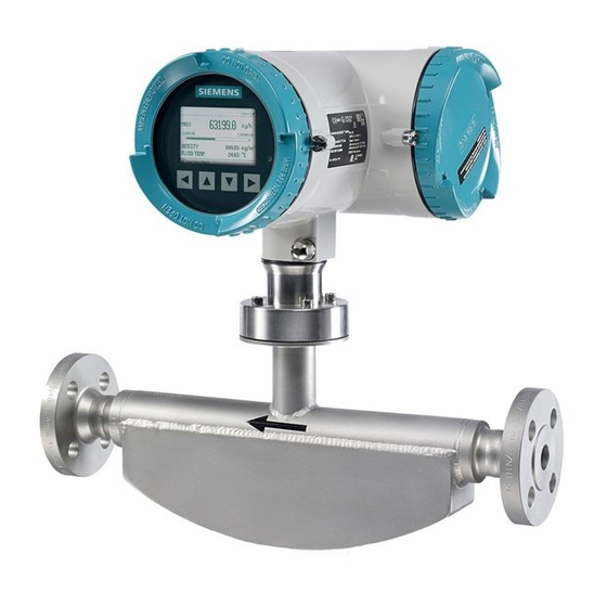
Design 3.2.1 Versions The flowmeter is available in a compact and a remote version. ● Compact version: The SITRANS FC330 is a single mechanical unit where the transmitter is directly mounted on the sensor. Figure 3-1 Compact version ● Remote version: The SITRANS FCS300 sensor unit is remotely connected to a SITRANS FCT030 transmitter. -
Page 23: Sensor Design
The sensors are available in AISI 316L stainless steel and C4 (2.4610) nickel alloy or C22 (2.4602) nickel alloy. The enclosure is made of Stainless steel 1.4404 (AISI 316L), 1.4301 (AISI SITRANS FC330 Operating Instructions, 01/2019, A5E44030648-AB... -
Page 24: Transmitter Design
The transmitter has a modular design with discrete, replaceable electronic modules and connection boards to maintain separation between functions and facilitate field service. All modules are fully traceable and their provenance is included in the transmitter setup. SITRANS FC330 Operating Instructions, 01/2019, A5E44030648-AB... - Page 25 USB service port M12 socket ⑨ ⑲ Transmitter cassette Terminal housing ⑩ ⑳ Heatsink cover for power supply module Sensor module (compact version) ⑪ ⑳ Cable entry Barrier module (remote version) Figure 3-6 Transmitter exploded view SITRANS FC330 Operating Instructions, 01/2019, A5E44030648-AB...
-
Page 26: Wall Mount Housing Transmitter Exploded View
Power supply connector cover ⑦ ⑯ Foam top Front cover enclosure ⑧ ⑰ Foam plugs Front cover mounting screws ⑨ Sensor module (analog version) Barrier module (digital version) Figure 3-7 Wall mount housing transmitter exploded view SITRANS FC330 Operating Instructions, 01/2019, A5E44030648-AB... -
Page 27: Device Identification
Device-specific system order number (transmitter and sensor) With compact versions, the transmitter and sensor product identifications are both given as 'SITRANS FC330'. With remote versions, the transmitter is identified as 'SITRANS FCT030' and the sensor as 'SITRANS FCS300'. SITRANS FC330 Operating Instructions, 01/2019, A5E44030648-AB... - Page 28 The flowmeter serial number consists of the following: PPYMDDXXXX where PP = Production factory (Siemens Flow Instruments: N1) Y = Production year (for encryption, see below) M = Production month (for encryption, see below) DD = Production day (for encryption, see below)
- Page 29 1968, 1988, 2008, 2028 1969, 1989, 2009, 2029 Month (M) Code January February March April June July August September October November December Day (DD) Code Day 01 to 31 01 to 31 (corresponding to the actual date) SITRANS FC330 Operating Instructions, 01/2019, A5E44030648-AB...
- Page 30 Consult the operating instructions ④ For Can / For US Country-specific restrictions ⑤ Ex approvals Classification for hazardous locations Note Approvals and identifications Approval certificates and notified body identifications are available for download at www.siemens.com (http://www.siemens.com/processinstrumentation/certificates). SITRANS FC330 Operating Instructions, 01/2019, A5E44030648-AB...
- Page 31 0518 Notified Body ID (ATEX example) ⑫ CE mark FCT030 transmitter approval nameplate example ① Conformity with country-specific directives ② QR code Product-specific QR code ③ WEEE symbol ④ C✓ Conformity with country-specific directives SITRANS FC330 Operating Instructions, 01/2019, A5E44030648-AB...
-
Page 32: Approvals
For further details see Certificates and approvals (Page 206). The device is available with approvals for general purpose and for hazardous areas. In all cases, check the nameplate on your device, and confirm the approval rating. SITRANS FC330 Operating Instructions, 01/2019, A5E44030648-AB... -
Page 33: Features
Features ● The flowmeter can be used as HART, Modbus RTU RS-485 or PROFIBUS PA/DP slave in operation on SIEMENS SIMATIC S7/PCS 7 or third party automation systems ● Available in compact and remote version ● Full graphical local display (HMI), with 6 user views and trend curves ●... - Page 34 ● Simulation of outputs ● Simulation of diagnostics ● Enabling alarms for visibility on all outputs (HMI, status and communication) ● Comprehensive diagnostics (NAMUR or Siemens standard) for troubleshooting and sensor checking ● Firmware update ● Use in hazardous areas according to specification ●...
-
Page 35: Applications
● Chemical & Pharma: detergents, bulk chemicals, acids, alkalis, pharmaceuticals, blood products, vaccines, insulin production ● Food & Beverage: dairy products, beer, wine, soft drinks, °Brix/°Plato, fruit juices and pulps, bottling, CO dosing, CIP/SIP-liquids, mixture recipe control SITRANS FC330 Operating Instructions, 01/2019, A5E44030648-AB... - Page 36 ● Automotive: fuel injection nozzle & pump testing, filling of AC units, engine consumption, paint robots ● Oil & Gas: filling of gas bottles, furnace control, test separators, bore-hole plasticizer dosing, water-cut metering ● Water & Waste Water: dosing of chemicals for water treatment SITRANS FC330 Operating Instructions, 01/2019, A5E44030648-AB...
-
Page 37: Installing/Mounting
Refer to the information in Technical data (Page 195). Note Material compatibility Siemens can provide you with support concerning selection of sensor components wetted by process media. However, you are responsible for the selection of components. Siemens accepts no liability for faults or failures resulting from incompatible materials. - Page 38 Refer to the information in Technical data (Page 195). WARNING Unprotected cable ends Risk of explosion through unprotected cable ends in hazardous areas. ● Protect unused cable ends in accordance with IEC/EN 60079-14. SITRANS FC330 Operating Instructions, 01/2019, A5E44030648-AB...
-
Page 39: Installation Location Requirements
Refer to the information in Installation in hazardous areas (Page 19). WARNING Equipment used in hazardous areas Risk of explosion in hazardous areas. Special requirements apply to the location and installation of the device. See Use in hazardous areas (Page 19). SITRANS FC330 Operating Instructions, 01/2019, A5E44030648-AB... -
Page 40: Proper Mounting
Risk of explosion. Damage to device if the enclosure is open or not properly closed. The type of protection specified on the nameplate or in Technical data (Page 195) is no longer guaranteed. ● Make sure that the device is securely closed. SITRANS FC330 Operating Instructions, 01/2019, A5E44030648-AB... -
Page 41: Installation Instructions
4.2.1.1 Remote field mount Mounting on wall 1. Prepare holes with aid of mounting bracket, see Mounting bracket dimensions (Page 223). 2. Fasten mounting bracket with black cushion pad to wall (torque 10 Nm). SITRANS FC330 Operating Instructions, 01/2019, A5E44030648-AB... -
Page 42: Wall Mount Housing
Mounting on wall Note Mounting screws are not included You will need four screws, able to support at least 55 lbs (25 kg). Siemens recommends M6x100 screws with appropriate anchors for the wall material. SITRANS FC330 Operating Instructions, 01/2019, A5E44030648-AB... - Page 43 Note Mounting on pipe or in panel For mounting on pipe or in panel see the installation instructions given in A5E45462317 Instructions "Pipe/panel mount kit" which is provided with the optional pipe/panel mount kit. SITRANS FC330 Operating Instructions, 01/2019, A5E44030648-AB...
- Page 44 U-bolts and other miscellaneous hardware are not supplied with the flowmeter. 2. Tighten nuts (torque: 10 Nm). Mounting in front panel 1. Cut out a hole in panel as shown. Figure 4-1 Panel cut-out dimensions 2. Remove lid from transmitter wall mount housing. SITRANS FC330 Operating Instructions, 01/2019, A5E44030648-AB...
-
Page 45: Turning The Transmitter (Compact Version)
– Bolt until screw lies against panel wall. 6. Tighten screws. 7. Remount lid. 4.2.1.3 Turning the transmitter (compact version) Horizontal rotation 1. Unscrew cap from lock screw. 2. Loosen lock screw at transmitter pedestal using 5 mm Allen key. SITRANS FC330 Operating Instructions, 01/2019, A5E44030648-AB... -
Page 46: Turning The Transmitter (Remote Version)
In a configuration with external DSL the transmitter can be turned horizontally and tilted vertically. Horizontal rotation 1. Unscrew cap from lock screw. 2. Loosen lock screw at transmitter pedestal using 5 mm Allen key. SITRANS FC330 Operating Instructions, 01/2019, A5E44030648-AB... - Page 47 5. Replace cap onto lock screw (torque: 10 Nm). Vertical rotation 1. Loosen locking cap at end of mounting bracket by three turns. 2. Carefully loosen and rotate transmitter into desired position (15° steps). 3. Firmly tighten locking cap (torque: 25 Nm). SITRANS FC330 Operating Instructions, 01/2019, A5E44030648-AB...
-
Page 48: Turning The Local Display
9. Mount O-ring by pulling it over the display cover and turn display cover until you feel friction from the O-ring on both sides. Wind display cover further by one quarter of a turn to seal on the O-ring. 10.Reinstall and tighten lid lock screw. SITRANS FC330 Operating Instructions, 01/2019, A5E44030648-AB... -
Page 49: Sensor Installation
Vapor condensation or oil traces in the gas may result in erroneous measurements. – Do not install the flowmeter at the lowest point of the system. – Install a filter. Figure 4-3 Gas applications, wrong location with trapped oil SITRANS FC330 Operating Instructions, 01/2019, A5E44030648-AB... -
Page 50: Orientation Of The Sensor
The sensor must always be completely filled with process media in order to measure accurately. NOTICE Orienting the sensor To avoid water or moist ingress, transmitters should be oriented with cable entrances aiming downwards. SITRANS FC330 Operating Instructions, 01/2019, A5E44030648-AB... - Page 51 Orienting the sensor The sensor operates in any orientation. The optimal orientation depends on the process fluid and the process conditions. Siemens recommends orienting the sensor in one of the following ways: 1. Vertical installation with an upwards flow (self-draining)
-
Page 52: Installation In A Drop Line
● Install two supports or hangers symmetrically and stress-free on the pipeline closely to the process connections. Note Handling Lift the flowmeter by the sensor body. Do not lift the flowmeter by the housing. SITRANS FC330 Operating Instructions, 01/2019, A5E44030648-AB... - Page 53 Non-flexible pipes not recommended in vibrating environment Figure 4-9 Flexible pipes recommended in vibrating environment Avoid cross talk When operating more than one flowmeter in one or multiple interconnected pipelines, there is a risk of cross talk. SITRANS FC330 Operating Instructions, 01/2019, A5E44030648-AB...
-
Page 54: Hydrostatic Testing
● To protect personnel from exposure to hot or cold surfaces, thereby preventing burns and other injuries ● To prevent heat loss into or out of the process, thereby preserving the process temperature and process medium conditions. SITRANS FC330 Operating Instructions, 01/2019, A5E44030648-AB... -
Page 55: Disassembly
● If the device contains hazardous media, it must be emptied prior to disassembly. Make sure that no environmentally hazardous media are released. ● Secure the remaining connections so that no damage can result if the process is started unintentionally. SITRANS FC330 Operating Instructions, 01/2019, A5E44030648-AB... - Page 56 Installing/mounting 4.3 Disassembly SITRANS FC330 Operating Instructions, 01/2019, A5E44030648-AB...
-
Page 57: Connecting
● For the electrical connection specifications, refer to the information in Technical data (Page 195). ● At the mounting location of the device observe the applicable directives and laws for installation of electrical power installations with rated voltages below 1000 V. SITRANS FC330 Operating Instructions, 01/2019, A5E44030648-AB... - Page 58 Risk of explosion through compensating currents between hazardous area and the non‑hazardous area. ● Shielded cables that cross into hazardous areas should be grounded only at one end. ● If grounding is required at both ends, use an equipotential bonding conductor. SITRANS FC330 Operating Instructions, 01/2019, A5E44030648-AB...
- Page 59 2. Connect the device in accordance with the selected type of protection. 3. In order to avoid incorrect use at a later point, make the types of protection that are not used permanently unrecognizable on the nameplate. SITRANS FC330 Operating Instructions, 01/2019, A5E44030648-AB...
-
Page 60: Connecting Fc330
This chapter describes how to wire up the device. The following steps must be carried out: ● Connecting the DSL and the transmitter (Page 62) (only remote version) ● Preparing for the transmitter connections (Page 65) SITRANS FC330 Operating Instructions, 01/2019, A5E44030648-AB... -
Page 61: Cable Requirements
Cable specifications ● When installing sensor cable, use cable with at least same degree of protection as the sensors. It is recommended to use cables supplied by Siemens: – blue cables for installation of intrinsically safe circuits in hazardous areas –... -
Page 62: Transmitter Power Supply And I/Os Connection
4. Push cable through open gland; anchor cable with clamp bar. Ensure that the clamp does not earth the screen. Apply heat-shrink sleeve to make sure the screen is only earthed at the sensor end. SITRANS FC330 Operating Instructions, 01/2019, A5E44030648-AB... - Page 63 Connecting 5.2 Connecting FC330 5. Connect wires to terminals according to list below. Terminal number Description Wire color (Siemens) 20 V Orange Yellow RS-485 / B White RS-485 / A Blue 6. Assemble and tighten cable gland 7. Remove O-ring from lid.
- Page 64 Connecting 5.2 Connecting FC330 8. Connect wires to terminals according to list below. Terminal number Description Wire color (Siemens cable) 20 V Orange Yellow RS-485 / B White RS-485 / A Blue 9. Ensure the DIP switches are all set to OFF.
-
Page 65: Preparing For The Transmitter Connections
Current output/communication outputs (channel 1) 2. Remove lid lock screw for terminal connections lid. 3. Remove lid for terminal connections. A label showing the configuration is placed at the back of the terminal connections lid. SITRANS FC330 Operating Instructions, 01/2019, A5E44030648-AB... - Page 66 Figure 5-2 Configuration label Terminal layout Field mount version Wall box version 24 V DC or 110/230 V AC For configuration of the inputs/outputs, see table in section Connecting channels 2 to 4 (Page 72). SITRANS FC330 Operating Instructions, 01/2019, A5E44030648-AB...
-
Page 67: Connecting The Current Hart, Ch1
Signal return (or common) can be joined. 1. Remove cap and ferrule from cable gland and slide onto cable. 2. Push cable through open gland and cable path. 3. Restore ferrule and tighten cap to lightly hold cable in place. SITRANS FC330 Operating Instructions, 01/2019, A5E44030648-AB... - Page 68 ⑥ ④ ⑤ Functional Earth Functional Earth Active current output Passive current output – Wall mount transmitter: Connect wires to terminals using wiring tool. Active current output Passive current output 5. Tighten cable gland. SITRANS FC330 Operating Instructions, 01/2019, A5E44030648-AB...
-
Page 69: Connecting The Modbus (Ch1)
Connecting the Modbus (CH1) 1. Remove cap and ferrule from cable gland and slide onto cable. 2. Push cable through open gland and cable path. 3. Restore ferrule and tighten cap to lightly hold cable in place. SITRANS FC330 Operating Instructions, 01/2019, A5E44030648-AB... - Page 70 Functional Earth – Wall mount transmitter: Connect wires to terminals using wiring tool. Modbus ④ In + (B) ⑤ In - (A) ⑥ Out + (B) ⑦ Out - (A) 5. Tighten cable gland. SITRANS FC330 Operating Instructions, 01/2019, A5E44030648-AB...
-
Page 71: Connecting The Profibus (Ch1)
2. Push cable through open gland and cable path. 3. Restore ferrule and tighten cap to lightly hold cable in place. 4. Signal cable screen is folded back over outer sheath and grounded beneath cable clamp. SITRANS FC330 Operating Instructions, 01/2019, A5E44030648-AB... -
Page 72: Connecting Channels 2 To 4
6. Tighten cable gland. 5.2.2.6 Connecting channels 2 to 4 Channel 2 is for output only and channels 3 to 4 can be connected as either inputs/outputs or relays, see Input/output configuration (Page 74). SITRANS FC330 Operating Instructions, 01/2019, A5E44030648-AB... - Page 73 Active configuration Passive configuration ⑫ ⑬ IO[3] (common) IO[3]- (passive) ⑪ ⑫ IO[3]+ (active) IO[3] (common) Functional Earth Functional Earth Table 5-1 If connected as input or output - Wall mount Active configuration Passive configuration SITRANS FC330 Operating Instructions, 01/2019, A5E44030648-AB...
-
Page 74: Input/Output Configuration
● Alarm class ChXa+ ● Alarm item Active ● NAMUR status signals Output Current output Frequency output Passive Pulse output ChX- Digital output ChXC ● Alarm class ChX+ ● Alarm item ● NAMUR status signals Passive SITRANS FC330 Operating Instructions, 01/2019, A5E44030648-AB... -
Page 75: Connecting The Power Supply - Field Mount
ChX- closed ChXC ChX+ Normally closed 5.2.2.8 Connecting the power supply - Field mount 1. Flip open power supply terminal protection cover. 2. Remove cap and ferrule from cable gland and slide onto cable. SITRANS FC330 Operating Instructions, 01/2019, A5E44030648-AB... - Page 76 L/+ and N/- using wiring tool in the manner shown below at right. ① ② ③ Protective Earth (PE) AC connection DC connection Power: 100 to 240 V AC, 47 to 63 Hz Power: 19.2 to 28.8 V DC SITRANS FC330 Operating Instructions, 01/2019, A5E44030648-AB...
-
Page 77: Connecting The Power Supply - Wall Mount
1. Open enclosure lid, unscrew power supply terminal protection cover screw, and remove protection cover. 2. Remove blind plug and fit cable gland. 3. Push cable through open gland and cable path 4. Restore ferrule and tighten cap to lightly hold cable in place. SITRANS FC330 Operating Instructions, 01/2019, A5E44030648-AB... -
Page 78: Finishing The Transmitter Connection
2. Firmly tighten cable glands and insert blanking plugs in unused cable entries. 3. Close lid. 4. Tighten the four spring screws. 5. Ensure that moisture does not penetrate to inside of electronics enclosure. SITRANS FC330 Operating Instructions, 01/2019, A5E44030648-AB... -
Page 79: Instructions Specific To Hazardous Area Installations
Special requirements apply to the location and interconnection of sensor and transmitter. See Installation in hazardous areas (Page 19). WARNING Transmitter housing Before opening the terminal box check that: ● No explosion hazard exists ● All connection leads are potential free SITRANS FC330 Operating Instructions, 01/2019, A5E44030648-AB... - Page 80 Connecting 5.3 Instructions specific to hazardous area installations SITRANS FC330 Operating Instructions, 01/2019, A5E44030648-AB...
-
Page 81: Commissioning
Hot surfaces Risk of burns resulting from hot surfaces. ● Take corresponding protective measures, for example by wearing protective gloves. Note Hot surface is only an issue for media or ambient temperature above 50 °C. SITRANS FC330 Operating Instructions, 01/2019, A5E44030648-AB... - Page 82 LEL. A value of 25% of the LEL is regarded as definitely safe. ● Do not introduce combustible or hazardous gases into a restricted-breathing enclosure (type of protection Ex nR). SITRANS FC330 Operating Instructions, 01/2019, A5E44030648-AB...
-
Page 83: Warnings
WARNING Improper handling The sensor connected to this device can be operated with high pressure and corrosive media. Therefore improper handling of the device can lead to serious injuries and/or considerable material damage. SITRANS FC330 Operating Instructions, 01/2019, A5E44030648-AB... -
Page 84: General Requirements
If one of the keys is pressed for more than 10 seconds, the calibration of this key begins which has a duration of less than 10 seconds. Release the key for further operation. SITRANS FC330 Operating Instructions, 01/2019, A5E44030648-AB... -
Page 85: Wizard Introduction
If you choose Yes (recommended), the Quick commissioning wizard will start. If you choose No, you accept the default values of the device, and the next HMI view will be the operation view 1. SITRANS FC330 Operating Instructions, 01/2019, A5E44030648-AB... -
Page 86: Zero Point Adjustment
The flowmeter system is optimized through a zero point adjustment which is performed via the Zero point adjustment wizard (Page 90). Performing a zero point adjustment CAUTION Gas application Zero point adjusting the device is only recommended for liquid applications. SITRANS FC330 Operating Instructions, 01/2019, A5E44030648-AB... - Page 87 5. At the end of the zero adjustment, the outcome is displayed as an offset and a standard deviation. Note If you get an error message after the zero point adjustment, refer to Zero point adjustment (Page 131). SITRANS FC330 Operating Instructions, 01/2019, A5E44030648-AB...
-
Page 88: Wizards
Quick commissioning wizard (menu item 1.1) The Quick commissioning wizard will guide you through configuration of parameters essential for your application. You configure parameters essential for your application by selecting the configuration path and subwizards appropriate for your application. SITRANS FC330 Operating Instructions, 01/2019, A5E44030648-AB... - Page 89 Process values wizard (menu item 1.3) (Page 92) Inputs and outputs wizard (menu item 1.4) (Page 94) Gas application wizard (menu item 1.5) (Page 99) Pulsating flow wizard (menu item 1.6) (Page 100) Dosing application wizard (menu item 1.7) (Page 101) SITRANS FC330 Operating Instructions, 01/2019, A5E44030648-AB...
-
Page 90: Zero Point Adjustment Wizard (Menu Item 1.2)
Ensure that the sensor has the same temperature as the process media. Perform at operating pressure or at least 0.2 barg. Clear diagnostic events Text Options/Description Clear diagnostic events "Clear diagnostic events" and alarm list are only shown if alarms are present. SITRANS FC330 Operating Instructions, 01/2019, A5E44030648-AB... - Page 91 *: Selecting Cancel will bypass the Zero point adjustment and end the wizard. Note View result Standard deviation and Offset values are only updated if the zero point adjustment was completed successfully. Otherwise the previous values are used. SITRANS FC330 Operating Instructions, 01/2019, A5E44030648-AB...
-
Page 92: Process Values Wizard (Menu Item 1.3)
The Process values wizard will guide you through the setup of process values for your application. The prioritizing of the process values automatically configures the measurement views on the display. The process value configured as 1st process value is set as first display view. SITRANS FC330 Operating Instructions, 01/2019, A5E44030648-AB... - Page 93 Commissioning 6.3 Local commissioning via HMI Text Options/Description Prioritize Prioritize the process values SITRANS FC330 Operating Instructions, 01/2019, A5E44030648-AB...
-
Page 94: Inputs And Outputs Wizard (Menu Item 1.4)
Current output - channel 1 The Current output on Channel 1 is a 4 to 20 mA output with Profibus, HART, Modbus. Channel 1 can be used in Functional Safety applications if ordered with SIL option. SITRANS FC330 Operating Instructions, 01/2019, A5E44030648-AB... - Page 95 Signal output - channels 2 to 4 The signal output can be configured to either current (0/4-20 mA), frequency, pulse, three- stage analog valve dosing control, discrete one or two-valve dosing control or alarm/status. SITRANS FC330 Operating Instructions, 01/2019, A5E44030648-AB...
- Page 96 Commissioning 6.3 Local commissioning via HMI SITRANS FC330 Operating Instructions, 01/2019, A5E44030648-AB...
- Page 97 The Relay output can be configured to either discrete one or two-valve dosing control or alarm/ status. Text Options/Description Status mode Select the status output functionality Configuration Configure the alarm (only if Alarm class or Individual alarms is selected) Output polarity and delay Set the output polarity and delay SITRANS FC330 Operating Instructions, 01/2019, A5E44030648-AB...
- Page 98 The Signal Input can be configured to either Dosing control, Totalizer reset, Remote zero adjust or Force/Freeze output(s). View Text Options/Description Operation Mode Select the signal input functionality Delay Time Set the signal input delay time Polarity Set the signal input polarity SITRANS FC330 Operating Instructions, 01/2019, A5E44030648-AB...
-
Page 99: Gas Application Wizard (Menu Item 1.5)
Standard volume flow. Text Options/Description Default values Select whether or not to use the default values Configure Configure empty tube detection and limit Standard volume flow Configure settings for standard volume flow SITRANS FC330 Operating Instructions, 01/2019, A5E44030648-AB... -
Page 100: Pulsating Flow Wizard (Menu Item 1.6)
As default the Totalizer will be set to Balanced, the Process noise damping is set to 4 and the Low flow cut-off value will be increased. Text Options/Description Default values Select whether or not to use the default values Configure Configure totalizer direction SITRANS FC330 Operating Instructions, 01/2019, A5E44030648-AB... -
Page 101: Dosing Application Wizard (Menu Item 1.7)
(discrete/analog) and fault handling. The valve control is done using channels 2, 3 and 4. View Text Options/Description Dosing Mode Select the dosing mode to control the valve(s) on the output Dosing options Setup instructions for the selected dosing mode SITRANS FC330 Operating Instructions, 01/2019, A5E44030648-AB... -
Page 102: Remote Commissioning With Pdm
For dosing setup, see Dosing (Page 145). Remote commissioning with PDM For commissioning with SIMATIC PDM, see separate function manuals for FCT030 Modbus, HART or PROFIBUS. See also Remote operation (Page 123) SIMATIC PDM (www.siemens.com/simatic-pdm) SITRANS FC330 Operating Instructions, 01/2019, A5E44030648-AB... -
Page 103: Operating
If one of the keys is pressed for more than 10 seconds, this key is calibrated (duration less than 10 seconds). Release the key for further operation. Note HMI timeout If no key is pressed for 10 minutes, the display switches to show operation view. SITRANS FC330 Operating Instructions, 01/2019, A5E44030648-AB... -
Page 104: Display View Structure
● Parameter view The Parameter view (Page 119) can be entered from the navigation view. The parameter view is used to view and edit the parameters. SITRANS FC330 Operating Instructions, 01/2019, A5E44030648-AB... - Page 105 Select the item below in the list; keep pressing the key to accelerate scrolling down the selection list Enter alarm view level 3 Table 7-4 Alarm view level 3 Function Enter alarm view level 2 No functionality No functionality No functionality SITRANS FC330 Operating Instructions, 01/2019, A5E44030648-AB...
- Page 106 Enter the navigation view The following graphic shows an example of how to navigate between measurement views and alarm views with measurement views 1, 3, and 4 as well as alarm view 5 enabled. SITRANS FC330 Operating Instructions, 01/2019, A5E44030648-AB...
- Page 107 Select the item above in the list; keep pressing the key to accelerate scrolling up the selection list. If the key is pressed when the top item is selected, the bottom item will be highlighted. SITRANS FC330 Operating Instructions, 01/2019, A5E44030648-AB...
- Page 108 Parameter edit view in access level read only Function Exit parameter edit view No functionality No functionality No functionality The exact structure of the operating menu is explained in the HMI menu structure (Page 237). SITRANS FC330 Operating Instructions, 01/2019, A5E44030648-AB...
-
Page 109: Access Control
PIN codes can be changed in menu 5 "Security". Note Lost PIN code If the PIN code is lost, provide Siemens customer support with the transmitter serial number (see nameplate). Siemens customer support will provide a code to be entered in "Change user PIN" (menu item 5.1). -
Page 110: Operation View
– One value and graph – Six values ● Operating views – Totalizer – Dosing ● Alarm view – Alarm List ● Diagnostic view – Six Diagnostic Values In general, all of the HMI views show the following: SITRANS FC330 Operating Instructions, 01/2019, A5E44030648-AB... -
Page 111: Measurement Views
Only shown if an alarm is active. 7.1.4 Measurement views Single value ① Process value The user-defined process value to be displayed is configured in menu 2 "Setup" → 2.8 "Local display" → 2.8.5 ... 2.8.10 "View" (1-6). SITRANS FC330 Operating Instructions, 01/2019, A5E44030648-AB... - Page 112 (e.g. menu 2.2.1 ... 2.2.6 for mass flow). ④ Bargraph Shows "1st Process value" in relation to its configured maximum and minimum limits (Upper Alarm LimitandLower Alarm Limitfor the selected process value). SITRANS FC330 Operating Instructions, 01/2019, A5E44030648-AB...
- Page 113 2 "Setup" → 2.8 "Local Display" → 2.8.5 ... 2.8.10 "View" (1-6). ⑥ Sixth process value The user-defined process value to be displayed is configured in menu 2 "Setup" → 2.8 "Local Display" → 2.8.5 ... 2.8.10 "View" (1-6). SITRANS FC330 Operating Instructions, 01/2019, A5E44030648-AB...
-
Page 114: Operating Views
Operating 7.1 Local operation (HMI) 7.1.5 Operating views Totalizer (level 1) ① Process value ② Graph ③ Instruction Press to enter the operation view. Totalizer (level 2) ① Process value ② Graph ③ Control SITRANS FC330 Operating Instructions, 01/2019, A5E44030648-AB... -
Page 115: Alarm Views
The complete alarm text can be viewed in the detailed alarm infor‐ mation view. ⑤ Alarm time stamp Timestamp with the actual date and time when the alarm occurred. ⑥ Current time Shows the current date and time. SITRANS FC330 Operating Instructions, 01/2019, A5E44030648-AB... - Page 116 ● Manual: The alarm remains in the alarm list until the alarm is manually acknowledged (ack.). The time of the acknowledgement is shown in the history log. ● Auto: The alarm is removed from the alarm list when the cause is removed (going) SITRANS FC330 Operating Instructions, 01/2019, A5E44030648-AB...
-
Page 117: Diagnostic Views
The navigation views present the menu structure of the device. All menu items are uniquely identified with menu item number. Level 1 of the navigation view (entered from the operation view) is standardized for all Siemens Process Instrumentation devices and covers the following groups: 1. - Page 118 When selected, the parameter is expanded into two lines. The second line shows the value of the parameter, a lock icon ( ) (only for read access level of the parameter), and an arrow in most right position. Figure 7-4 Navigation view ReadWrite SITRANS FC330 Operating Instructions, 01/2019, A5E44030648-AB...
-
Page 119: Parameter View
Confirm and save (frame around OK is only shown when cursor is in right-most position) ⑥ Value to be edited ⑦ Minimum value ⑧ Help text describing the parameter function. The help text appears if no key is pressed for three seconds. Figure 7-6 Numeric parameter edit view SITRANS FC330 Operating Instructions, 01/2019, A5E44030648-AB... - Page 120 The resolution can also be changed by setting the decimal places parameter for the selected process value, for example the decimal places for process value mass flow is defined in parameter menu item 2.2.1.4. SITRANS FC330 Operating Instructions, 01/2019, A5E44030648-AB...
- Page 121 Help text describing the parameter function. The help text appears if no key is pressed for three seconds. Figure 7-8 List Selection edit view Select the value by using keys, and press to confirm changes. Press to escape the view without changing the value. SITRANS FC330 Operating Instructions, 01/2019, A5E44030648-AB...
- Page 122 Help text describing the parameter function. The help text appears if no key is pressed for three seconds. to scroll through the alarms. Use to select/deselect the alarm. The marked alarms will NOT be suppressed. Note Save settings To activate the selections, press to save settings before leaving the view. SITRANS FC330 Operating Instructions, 01/2019, A5E44030648-AB...
-
Page 123: Remote Operation
Many of the major vendors have stated that their configuration software will evolve into being an FDI host. At the time this manual was written, Siemens had announced that SIMATIC PDM will become a FDI host system in the near future. - Page 124 See also Device identification (Page 27) Mobile App "Industry Online Support" (https://support.industry.siemens.com/cs/ww/de/sc/ 2067) Procedure Note If you click on "Cancel" during an upload from the device to SIMATIC PDM some parameters will be updated. SITRANS FC330 Operating Instructions, 01/2019, A5E44030648-AB...
- Page 125 7. Upload parameters to the PC/PG. 8. Configure the device via the Quick Start wizard. Open in SIMATIC PDM the menu Device – Set Address, enter a value for New Address, and click on Assign Address. SITRANS FC330 Operating Instructions, 01/2019, A5E44030648-AB...
- Page 126 Operating 7.2 Remote operation SITRANS FC330 Operating Instructions, 01/2019, A5E44030648-AB...
-
Page 127: Parameter Assignment
Parameters not followed by a number are accessible only via remote operation. Functions 8.2.1 Process values The process values are updated every 10 ms (100 Hz update rate) synchronous with the DSP update cycle. SITRANS FC330 Operating Instructions, 01/2019, A5E44030648-AB... - Page 128 Upper Limit Warning or the Lower Limit Warning. Process value alarms and warnings are displayed in the HMI as well as at the communication interfaces. Hysteresis The hysteresis functions as follows: Figure 8-1 Hysteresis SITRANS FC330 Operating Instructions, 01/2019, A5E44030648-AB...
- Page 129 In this measurement context, phase difference is expressed not in degrees of rotation but as an absolute time measurement. For this reason the result of zero offset correction is displayed in µs, being the unit of the true measurement. SITRANS FC330 Operating Instructions, 01/2019, A5E44030648-AB...
- Page 130 Fraction calculations are naturally performed in the ratio provided, or in mass ratio when using the built-in tables. Volume or mass ratios derived from the fraction table are calculated through the composite media density. SITRANS FC330 Operating Instructions, 01/2019, A5E44030648-AB...
-
Page 131: Zero Point Adjustment
Successful automatic zero point adjustment If the new zero point offset value is valid, it is automatically stored as the new zero point for the sensor. It remains stored in the case of a power failure. SITRANS FC330 Operating Instructions, 01/2019, A5E44030648-AB... -
Page 132: Low Flow Cut-Off
The empty tube monitoring is activated via the Empty Tube Detection parameter. When the empty tube monitoring function is on, the mass flow / volume flow value is forced to zero if the tube is empty. SITRANS FC330 Operating Instructions, 01/2019, A5E44030648-AB... -
Page 133: Process Noise Damping
The default value is Duplex pump. The damping affects all functions and outputs of the sensor. Simplex pump (4) Centrifugal pump Triplex pump (2) Duplex pump Cam pump (5, high) (1, low) (3; default setting) SITRANS FC330 Operating Instructions, 01/2019, A5E44030648-AB... -
Page 134: Inputs And Outputs
● Operational and alarm status Relay output ● Discrete one or two-valve dosing control ● Operational and alarm status Signal input ● Dosing control ● Totalizer reset ● Remote zero adjust ● Force or freeze output(s) SITRANS FC330 Operating Instructions, 01/2019, A5E44030648-AB... -
Page 135: Current Output
The accuracy specified for the analog output signal applies only within the range 4 to 20 mA. Lower limit (4 mA) and upper limit (20 mA) can be assigned to any specific flow values. SITRANS FC330 Operating Instructions, 01/2019, A5E44030648-AB... - Page 136 In the alarms lists inDevice status symbols (Page 167) it is listed which alarms bring the output to fail safe current. Output scaling configuration Below are four examples describing configuration possibilities for a current output. SITRANS FC330 Operating Instructions, 01/2019, A5E44030648-AB...
- Page 137 ● Current Mode = 4-20 mA (maximum 25 mA) ● Upper Scaling = 100 kg/h ● Lower Scaling = 400 kg/h ● Fail Safe Mode = Maximum current ● Low-Flow Cut-Off = 25 kg/h SITRANS FC330 Operating Instructions, 01/2019, A5E44030648-AB...
- Page 138 ● Direction = Bidirectional ● Current Mode = 4-20 mA NAMUR ● Upper Scaling = 400 kg/h ● Lower Scaling = -100 kg/h ● Fail Safe Mode = Maximum current ● Low Flow Cut-Off = 25 kg/h SITRANS FC330 Operating Instructions, 01/2019, A5E44030648-AB...
- Page 139 ● Direction = Bidirectional ● Current Mode = 4-20 mA US ● Upper Scaling = 400 kg/h ● Lower Scaling = -100 kg/h ● Fail Safe Mode = Minimum current ● Low Flow Cut-Off = 25 kg/h SITRANS FC330 Operating Instructions, 01/2019, A5E44030648-AB...
-
Page 140: Pulse Output
Pulse output The pulse output function supplies pulses equivalent to a configured amount of accumulated volume or mass. The pulse width is configured and the pulse repetition is proportional to the selected flow rate. SITRANS FC330 Operating Instructions, 01/2019, A5E44030648-AB... -
Page 141: Frequency Output
This example shows how to calculate the output frequency for any measured flowrate: Frequency output configuration: ● Operation Mode = Frequency Output (Channel 2 to 4) ● Process value = Mass flow ● Direction = Positive SITRANS FC330 Operating Instructions, 01/2019, A5E44030648-AB... -
Page 142: Redundancy Mode (Frequency)
Channel 2 configured as positive direction and channel 3 set to redundancy mode 90° Figure 8-3 Positive flow - channel 3 leads by 90° Figure 8-4 Negative flow - channel 3 lags by 90° SITRANS FC330 Operating Instructions, 01/2019, A5E44030648-AB... - Page 143 Figure 8-8 Negative flow - channel 3 lags by 90° Channel 2 configured as positive direction and channel 3 set to redundancy mode 180˚ Figure 8-9 Positive flow - channel 3 leads by 180° SITRANS FC330 Operating Instructions, 01/2019, A5E44030648-AB...
-
Page 144: Digital Output
The alarm class options depend on the Alarm Mode setting, either NAMUR or Standard (Siemens Standard), selected in menu item 2.8.11. Both NAMUR and Siemens Standard alarms and their messages are described in more detail in Fault codes and corrective actions (Page 171). -
Page 145: Totalizers
Amount. The process values for dosing control are updated with 100 Hz to ensure maximum response time of 10 ms to rapidly changing flows. SITRANS FC330 Operating Instructions, 01/2019, A5E44030648-AB... - Page 146 – Setup dosing name, amount, unit and compensation – Select valve control sequence – Select fault handling configuration 3. Output(s) in "Inputs/Outputs" (menu item 2.4). 4. Input for dosing control in "Inputs/Outputs" (menu item 2.4). SITRANS FC330 Operating Instructions, 01/2019, A5E44030648-AB...
-
Page 147: Dosing Control Configuration
● Mass flow ● Volume flow ● Standard volume flow ● Fraction A ● Fraction B Recipes Five recipes can be configured individually, however only one of the recipes can be active at a time. SITRANS FC330 Operating Instructions, 01/2019, A5E44030648-AB... -
Page 148: Valve Control Configuration
"Operation Mode" Status Output 2.4.6.27 "Status Mode" Primary Valve Dosing Relay output 2.4.4.1 "Status Mode" Primary Valve Dosing 2.4.7.1 "Status Mode" Primary Valve Dosing Two on/off valves Configuration of two valves (primary and secondary valves) SITRANS FC330 Operating Instructions, 01/2019, A5E44030648-AB... - Page 149 "Process Value" Control valve 2.4.6.1 "Operating Mode" Current Output 2.4.6.2 "Process Value" Control valve Note If the output channels including current output are configured for valve control, they cannot report alarm status or fault levels. SITRANS FC330 Operating Instructions, 01/2019, A5E44030648-AB...
- Page 150 - 2.5.5.6.2 Stage 1 Primary Open = 0 % - 2.5.5.6.3 Stage 1 Primary Close = 66 % - 2.5.5.6.4 Stage 2 Secondary Open = 33 % - 2.5.5.6.5 Stage 2 Secondary Close = 100 % SITRANS FC330 Operating Instructions, 01/2019, A5E44030648-AB...
- Page 151 - 2.5.5.6.2 Stage 1 Primary Open = 33 % - 2.5.5.6.3 Stage 1 Primary Close = 66 % - 2.5.5.6.4 Stage 2 Secondary Open = 0 % - 2.5.5.6.5 Stage 2 Secondary Close = 100 % SITRANS FC330 Operating Instructions, 01/2019, A5E44030648-AB...
- Page 152 The quantity or percent of amount at which the valve will transition from Amount partial to full flow Partially Closed 100.00 % of The quantity or percent of amount at which the valve will transition from Amount full flow to partial flow SITRANS FC330 Operating Instructions, 01/2019, A5E44030648-AB...
-
Page 153: Dosing Operation
Compensation). 8.2.8.4 Fault handling The transmitter fault handling provides monitoring of both dosing time and amount. The configuration of the fault handling is done in Fault handling (menu item 2.5.5.6 for Recipe 1) . SITRANS FC330 Operating Instructions, 01/2019, A5E44030648-AB... -
Page 154: Audit Trail Logging
See also "Diagnostic log (Page 154)" (menu item 3.2.2) 8.2.10 Diagnostic log All unacknowledged diagnostic information are listed in the "Diagnostic log" (menu item 3.2.2). The diagnostic alarm list is default available in operating view 6. SITRANS FC330 Operating Instructions, 01/2019, A5E44030648-AB... -
Page 155: Custom Unit
Further is contains parameter backup files, firmware logs, alarm history log, parameter change log and data logging of process values and parameters. The Siemens SensorFlash memory unit offers a permanent database with backup of all parameter settings. The SensorFlash supports copy and transfer of user settings from one flowmeter to another to simplify commissioning. -
Page 156: Datalogging On Sensorflash
● Frequency ● 0 to 12.5 kHz ● Status ● 0 (low) or 1 (high) Process value simulation The following process values can be simulated: ● Mass flow ● Volume flow ● Standard Volume flow SITRANS FC330 Operating Instructions, 01/2019, A5E44030648-AB... -
Page 157: Maintenance
Alarm simulation It is possible to simulate either specific alarms (ID numbers) or alarm classes. The alarm classes are either Siemens or NAMUR depending on the configuration of Alarm Mode, menu item 2.8.11. Any simulated alarms will be time-stamped 1900-01-01 00:00 if the alarms have not previously appeared as real alarms. - Page 158 Parameter assignment 8.2 Functions SITRANS FC330 Operating Instructions, 01/2019, A5E44030648-AB...
-
Page 159: Service And Maintenance
Use of a computer in a hazardous area If the interface to the computer is used in the hazardous area, there is a risk of explosion. ● Ensure that the atmosphere is explosion-free (hot work permit). SITRANS FC330 Operating Instructions, 01/2019, A5E44030648-AB... -
Page 160: Recalibration
● Make sure when carrying out cleaning and maintenance work that no moisture penetrates the inside of the device. Recalibration Siemens S.A.S. Flow Instruments offers to recalibrate the sensor at our works in France. The following calibration types are offered as standard according to configuration: ● Standard calibration ●... -
Page 161: Maintenance And Repair Work
● Repair must be carried out by Siemens authorized personnel only. WARNING Impermissible repair and maintenance of the device ● Repair and maintenance must be carried out by Siemens authorized personnel only. WARNING Impermissible repair of explosion protected devices Risk of explosion in hazardous areas ●... - Page 162 Temperatures that can burn unprotected skin may be present for some time after the device has been switched off. ● Observe the waiting time specified in Technical data (Page 195) or on the device before starting with maintenance work. SITRANS FC330 Operating Instructions, 01/2019, A5E44030648-AB...
- Page 163 WARNING Improper connection after maintenance Risk of explosion in areas subject to explosion hazard. ● Connect the device correctly after maintenance. ● Close the device after maintenance work. Refer to Cable requirements (Page 61). SITRANS FC330 Operating Instructions, 01/2019, A5E44030648-AB...
-
Page 164: Service Information
● Pickup 1 Amplitude ● Pickup 2 Amplitude ● Sensor Frequency ● Frame Temperature ● Process Media Temperature ● Zero Point Adjustment Auto/Manual ● Zero Point Offset Value ● Manual Zero Point ● Zero Point Standard Deviation SITRANS FC330 Operating Instructions, 01/2019, A5E44030648-AB... -
Page 165: Replacing The Device
– Number of returned devices/replacement parts – Reason for returning the item(s) ● Decontamination declaration (http://www.siemens.com/sc/declarationofdecontamination) With this declaration you warrant "that the device/replacement part has been carefully cleaned and is free of residues. The device/replacement part does not pose a hazard for humans and the environment."... -
Page 166: Disposal
● Dispose of the device properly and environmentally through a local waste disposal contractor. Ex-approved products Note Repair of Ex-approved products It is the customer's responsibility that repair of Ex-approved products fulfill national requirements. SITRANS FC330 Operating Instructions, 01/2019, A5E44030648-AB... -
Page 167: Diagnostics And Troubleshooting
The following table provides possible cause of device status, and actions for the user or service. The device provides two types of alarm formats; symbols used on the local display are based on NAMUR status signals or Siemens standard alarm classes, selected in parameter "Status icons" (menu item 2.8.11). - Page 168 Diagnostics and troubleshooting 10.1 Device status symbols Device status symbols Local display NAMUR Local display SIMATIC PDM/PLC - NAMUR NE 107 - HCF - Siemens standard Symbol Device Priority * Priority * Symbol Device Priority ** Symbol Device status Priority **...
- Page 169 Cause: Device status ok. No active diagnostic errors. Action: No action required. * Lowest priority number equals highest fault severity. ** Both the Siemens standard symbol and its corresponding Namur symbol (from device display) will be shown in SIMATIC PDM. Messages are shown in the display.
- Page 170 10.1 Device status symbols Characteristics of messages The device provides two types of alarm formats, Siemens standard alarm classes and NAMUR status signals, selected in Status icons. The following tables summarize the two types of alarm formats in an overview.
-
Page 171: Fault Codes And Corrective Actions
Sensor supply volt. out of Contact your local Siemens representative. range Temperature measure‐ Turn off the power, wait 5 seconds and turn on the power ment fault again. If the problem persists, contact your local Siemens representative. SITRANS FC330 Operating Instructions, 01/2019, A5E44030648-AB... - Page 172 Temperature measure‐ Turn off the power, wait 5 seconds and turn on the power ment fault again. If the problem persists, contact your local Siemens representative. Temperature measure‐ Turn off the power, wait 5 seconds and turn on the power ment fault again.
- Page 173 Malfunction in sensor driv‐ Contact your local Siemens representative. Malfunction in sensor driv‐ Contact your local Siemens representative. Unstable driver oscillation Contact your local Siemens representative. Mass flow out of specifica‐ Reduce the flow. If the problem persists, contact your local tion Siemens representative.
- Page 174 Message Cause/Action Fluid temp. below limit Increase the fluid temperature. If the problem persists, con‐ tact your local Siemens representative. Fluid temp. above limit Reduce the fluid temperature. If the problem persists, con‐ tact your local Siemens representative. Frame temp. below limit Increase fluid temperature and check that ambient temper‐...
- Page 175 Cause/Action Parameter storage mal‐ Turn off the power, wait 5 seconds and turn on the power function again. If the problem persists, contact your local Siemens representative. Internal error in sensor Contact your local Siemens representative. Internal error in sensor Contact your local Siemens representative.
-
Page 176: Transmitter Diagnostics
Check process conditions. Adjust parameter value 'Upper limit alarm limit' to normal process conditions. Volume flow above warn‐ Check process conditions. Adjust the parameter value 'Up‐ ing limit per warning limit' to normal process conditions. SITRANS FC330 Operating Instructions, 01/2019, A5E44030648-AB... - Page 177 Check process conditions. Adjust the parameter value 'Up‐ above warning limit per warning limit' to normal process conditions. Medium temperature be‐ Check process conditions. Adjust the parameter value low warning limit 'Lower warning limit' to normal process conditions. SITRANS FC330 Operating Instructions, 01/2019, A5E44030648-AB...
- Page 178 Check process conditions. Adjust the parameter value ing limit 'Lower warning limit' to normal process conditions. Fraction B % below alarm Check process conditions. Adjust the parameter value limit 'Lower alarm limit' to normal process conditions. SITRANS FC330 Operating Instructions, 01/2019, A5E44030648-AB...
- Page 179 Check process conditions. Adjust the parameter value limit 'Lower alarm limit' to normal process conditions. Standard density above Check process conditions. Adjust the parameter value 'Up‐ alarm limit per alarm limit' to normal process conditions. SITRANS FC330 Operating Instructions, 01/2019, A5E44030648-AB...
- Page 180 Check process conditions. Adjust the parameter value 'Up‐ limit per alarm limit' to normal process conditions. Totalizer 1 above warning Check process conditions. Adjust the parameter value 'Up‐ limit per warning limit' to normal process conditions. SITRANS FC330 Operating Instructions, 01/2019, A5E44030648-AB...
- Page 181 Check process conditions. Adjust the parameter value 'Up‐ limit per warning limit' to normal process conditions. Totalizer 3 below warning Check process conditions. Adjust the parameter value limit 'Lower warning limit' to normal process conditions. SITRANS FC330 Operating Instructions, 01/2019, A5E44030648-AB...
- Page 182 Inspect the device for cold- related damages. Sensor signal disrupted Turn off the power. Unplug and reconnect the sensor cable. If the error still exists, contact your local Siemens repre‐ sentative. SensorFlash parameter A SensorFlash of another device has been inserted. Either...
- Page 183 Internal error Internal error in transmitter. Turn off the power, wait 5 sec‐ onds and turn on the power again. If the error still exists, contact your local Siemens representative. Mass flow simulated Disable the simulation to return to normal operation.
- Page 184 If the problem persists, contact Technical Support. Transmitter firmware in‐ The component does not have the expected firmware ver‐ compatible sion. Update the product firmware or replace the compo‐ nent. SITRANS FC330 Operating Instructions, 01/2019, A5E44030648-AB...
- Page 185 CH2 loop current in upper The process value is so high that the loop current reaches saturation the upper saturation limit and cannot increase any further. Check process conditions. Adjust parameter value 'Upper range value'. SITRANS FC330 Operating Instructions, 01/2019, A5E44030648-AB...
- Page 186 Check process conditions. Adjust parameter value 'Lower range value'. CH3 output frequency too The process value is above the parameter 'Upper range high value'. The output frequency cannot increase any further. Check process conditions. Adjust parameter value 'Upper range value'. SITRANS FC330 Operating Instructions, 01/2019, A5E44030648-AB...
- Page 187 Pulse output has insufficient pulse separation. Increase Amount per pulse, or reduce Pulse width, or reduce Pulses per amount. Invalid dosing settings Correct settings. CH2 simulated Disable the simulation to return to normal operation. SITRANS FC330 Operating Instructions, 01/2019, A5E44030648-AB...
- Page 188 Invalid Modbus register At least one source register has been used multiple times. mapping Correct the register mapping. Invalid Modbus coil config‐ A coil has multiple assignments. Correct the coil configu‐ uration rations. SITRANS FC330 Operating Instructions, 01/2019, A5E44030648-AB...
-
Page 189: Operation Troubleshooting
The device synchronizes the parameters to the SensorFlash. The alarm is cleared. 10.3.2 Updating the firmware 1. Download the new firmware bundle from www.siemens.com/FC330 (www.siemens.com/ FC330)and save it to the SensorFlash. An instruction is also available at this site. 2. Access the flowmeter with access level Expert (the default PIN code is 2834). -
Page 190: Troubleshooting Sensor-Related Problems
Step 1: Inspecting the application Ensure that: 1. The sensor is installed as described in Installing/mounting (Page 37). 2. The sensor is located in a vibration-free position. Vibrations can disturb the sensor and therefore cause measurement error. SITRANS FC330 Operating Instructions, 01/2019, A5E44030648-AB... - Page 191 ● The error curve is plotted from the formula: z x 100 E = ± (Cal) = Error [%] = Zero point [kg/h] = Mass flow [kg/h] Cal. = Calibrated flow accuracy: 0.10 or 0.2 SITRANS FC330 Operating Instructions, 01/2019, A5E44030648-AB...
- Page 192 ("View → Process variables") This information can be used to troubleshoot. For example, tightening the brackets which hold the sensor, or turning off the pump to check if vibrations from the pump are disturbing the sensor, etc. SITRANS FC330 Operating Instructions, 01/2019, A5E44030648-AB...
- Page 193 ● The entry pipe and sensor have not been properly filled with liquid. ● The pump cavitates, the rotary speed of the pump is too high in relation to the supply of liquid to the pump. SITRANS FC330 Operating Instructions, 01/2019, A5E44030648-AB...
- Page 194 1. Ensure that the sensor is installed vertically with an upwards flow. 2. Check if solid particles are present in the liquid: Take a sample of the liquid, fill a glass and see if the solids precipitate. SITRANS FC330 Operating Instructions, 01/2019, A5E44030648-AB...
-
Page 195: Technical Data
Technical data Note Device specifications Siemens makes every attempt to ensure the accuracy of these specifications but reserves the right to change them at any time. 11.1 Power Table 11-1 Power supply Description Specification Supply voltage ● 100 to 240 V AC, 47 to 63 Hz 30 VA ●... - Page 196 Sensor size DN15 DN25 DN50 DN80 DN100 DN150 Current output as pulse output ±(0.1% of actual flow + 0.05% FSO) Effect of process pressure % of actual <-0.002 <-0.013 <-0.01 -0.006 <-0.009 <-0.035 flowrate per SITRANS FC330 Operating Instructions, 01/2019, A5E44030648-AB...
-
Page 197: Interface
11.3.2 HART interface Table 11-8 HART communication Description Specification HART revision PROFIBUS interface Table 11-9 Profibus DP/PA Description Specification Profile version V4.0 - compatible with version 3 Default transmission rate Automatic baud rate detection SITRANS FC330 Operating Instructions, 01/2019, A5E44030648-AB... -
Page 198: Inputs
Standard industrial signal cable with up to 3 twisted pairs with overall screen can be con‐ nected between the transmitter and the control system. Individual pair or overall screen is optional depending on user requirements. Voltage range Max. 24 V DC (active) 14 to 30 V DC (passive) SITRANS FC330 Operating Instructions, 01/2019, A5E44030648-AB... - Page 199 0 to 100 s Active 0 to 24 V DC, 87 mA, short-circuit-protected Passive 3 to 30 V DC, 100 mA, short-circuit-protected Functions ● Pulse ● Frequency ● Alarm class / NAMUR status ● Individual alarms SITRANS FC330 Operating Instructions, 01/2019, A5E44030648-AB...
-
Page 200: Construction
18 to 1000 Hz random, 3.17 g RMS, in all direc‐ tions, to IEC 68-2-36 Torques Table 11-18 Installation torques Description Torque (Nm) Pressure guard fittings G 1/4 inch Wall bracket screws Transmitter to wall bracket SITRANS FC330 Operating Instructions, 01/2019, A5E44030648-AB... -
Page 201: Sensor Design
Torque (Nm) Transmitter pedestal lock screw Compact version: Remote version: Pedestal lock screw cap Cable gland to housing (Siemens supplied, metric) Note NPT glands When using NPT glands, the user must take care to use the supplied NPT thread adaptors. 11.6.1... -
Page 202: Sensor Cable Specifications Hart
100 (±5) Attenuation @ 1 Mhz < 2.9 dB/100 m Operating voltage (peak) [V] ≤ 300 Test voltage (wire/wire/screen rms 50 Hz 1 min) [V] = 700 Electrical data at reference temperature (20 °C) SITRANS FC330 Operating Instructions, 01/2019, A5E44030648-AB... - Page 203 (plastic or rubber) under the threads where they screw into the terminal housing or enclosure. SITRANS FC330 Operating Instructions, 01/2019, A5E44030648-AB...
-
Page 204: Operating Conditions
Process media absolute pressure (min to max) [bar (psi)] Stainless steel: 1 to 101 (14.5 to 1465) Process media viscosity Gases and non-compressible liquids Pressure drop See Siemens Sizing & Calculation tool (www.siemens.com/pisizer). Select "Flow" > "SITRANS F C sizing". Pressure temperature ratings See "Pressure - temperature ratings"... -
Page 205: Process Variables
Number of device variables Number of process values, both measured and derived Physical layers supported Frequency Shift Keyed Loop-powered 4-wire device Note Device-specific approvals Always refer to nameplates on the device for device-specific approvals. SITRANS FC330 Operating Instructions, 01/2019, A5E44030648-AB... -
Page 206: Certificates And Approvals
-40 to +85 °C (-40 to 185 °F) Storage: -40 to +100 °C (-40 to 212 °F) Note SensorFlash functions support Only the supplied 4 GB SD cards are supported for backup, restore, logging, and firmware update. SITRANS FC330 Operating Instructions, 01/2019, A5E44030648-AB... -
Page 207: Ped
This must be within the limits defined for the equipment. Division of media (liquid/gaseous) into the fluid groups Fluids are divided according to Article 13 into the following fluid groups: SITRANS FC330 Operating Instructions, 01/2019, A5E44030648-AB... - Page 208 R phrases: for example: 2, 3 (1, 4, 5, 6, 9, 16, 18, R phrases: for example: 26, 27, 28, 39 (32) 19, 44) Extremely flammable Toxic R phrases: for example: 12 (17) R phrases: for example: 23, 24, 25 (29, 31) SITRANS FC330 Operating Instructions, 01/2019, A5E44030648-AB...
- Page 209 The flowmeters are subjected to the conformity assessment procedure - Module H. Flowmeters according to Article 4 Paragraph 3 are designed and manufactured in accordance with sound engineering practice in Denmark. PED conformity reference is not affixed to the CE mark. SITRANS FC330 Operating Instructions, 01/2019, A5E44030648-AB...
- Page 210 ● Exception: liquids at temperatures > 350 °C belonging to Category II must be included in Category III. PS [bar] 1000 Article 3 Paragraph 3 PS = 0,5 2000 7000 1000 10000 Figure 11-2 Diagram 2 SITRANS FC330 Operating Instructions, 01/2019, A5E44030648-AB...
-
Page 211: Pressure - Temperature Ratings
Design rules for flange connections in both the EN1092-1 and ASME B16.5 standards dictate pressure derating with increasing temperature. The charts below show the effect of process medium temperature on the pressure ratings for the flanges within the product program. SITRANS FC330 Operating Instructions, 01/2019, A5E44030648-AB... -
Page 212: Pressure - Temperature Ratings (Stainless Steel Sensors)
Table 11-29 EN1092-1 [bar] PN (bar) Temperature TS (°C) 16.0 16.0 16.0 15.2 13.7 13.1 12.7 40.0 40.0 40.0 37.9 34.5 32.9 31.8 63.0 63.0 63.0 59.7 54.3 51.8 50.1 100.0 100.0 100.0 94.8 86.1 82.1 79.5 SITRANS FC330 Operating Instructions, 01/2019, A5E44030648-AB... - Page 213 99.3 99.3 96.2 84.4 77.0 71.3 900 / 2.2 124.1 120.1 104.4 94.2 87.5 1500 / 2.2 206.8 200.1 173.9 145.8 Table 11-32 JIS [bar] PN (bar) Temperature TS (°C) 13.4 12.4 33.1 31.6 SITRANS FC330 Operating Instructions, 01/2019, A5E44030648-AB...
-
Page 214: Pressure - Temperature Ratings (Nickel Alloy Sensors)
Maximum allowable test pressure (MATP) for the flowmeter and process connection is 1.5 times the nominal pressure up to 150 bar (2176 psi). 11.13.2 Pressure - temperature ratings (nickel alloy sensors) Figure 11-7 Nickel alloy: Metric flange ratings, EN 1092-1 (P: Process pressure; T: Process temperature) SITRANS FC330 Operating Instructions, 01/2019, A5E44030648-AB... - Page 215 Nickel alloy: ANSI flange ratings, ASME B16.5 (P: Process pressure; T: Process temperature) Table 11-36 ASME B16.5 [bar] Class Temperature TS (°C) 20.0 20.. 19.5 17.7 15.8 13.8 51.7 51.7 51.7 51.5 50.3 48.6 103.4 103.4 103.4 103.0 100.3 97.2 145.0 134.0 125.0 SITRANS FC330 Operating Instructions, 01/2019, A5E44030648-AB...
- Page 216 Technical data 11.13 Pressure - temperature ratings SITRANS FC330 Operating Instructions, 01/2019, A5E44030648-AB...
-
Page 217: Dimension Drawings
525 (20.67) 90 (3.54) 66.5 (147) 100 (4”) 262 (10.31) 622 (24.49) 90 (3.54) 128 (282.19) 150 (6”) 317 (12.48) 714 (28.11) 90 (3.54) 207 (456.36) Note The built-in length (D) depends on the flange SITRANS FC330 Operating Instructions, 01/2019, A5E44030648-AB... -
Page 218: Stainless Steel - Standard
EN 1092-1 B1, PN 16 1222 1122 1260 1569 1421 (34.45) (48.11) (44.17) (49.61) (61.77) (55.94) EN 1092-1 B1, PN 40 1222 1144 1260 1599 1461 1650 (35.83) (34.25) (34.45) (48.11) (45.04) (49.61) (62.95) (57.52) (64.96) SITRANS FC330 Operating Instructions, 01/2019, A5E44030648-AB... -
Page 219: Stainless Steel Polished - Hygienic Versions
• Meter tube nominal diameter DN 80 (3"): +0 / -5 mm (+0 / -0.2 in.) • Meter tube nominal diameter DN 100 ... 150 (4" ... 6"): +0 / -8 mm (+0 / -0.31 in.) SITRANS FC330 Operating Instructions, 01/2019, A5E44030648-AB... -
Page 220: Nickel Alloy
(25.4) (24.2) (22.7) (32.0) (30.1) (32.2) ANSI B16.5, class 300 (17.4) (16.9) (25.4) (24.2) (22.7) (32.0) (30.1) (32.2) ANSI B16.5, class 600 (17.4) (16.9) (25.4) (24.2) (22.7) (32.0) (30.1) (32.2) Dimensions in mm (inch) SITRANS FC330 Operating Instructions, 01/2019, A5E44030648-AB... -
Page 221: Transmitter Dimensions
(50.4) (49.6) (64.3) (60.7) ANSI B16.5, class 600 1021 1357 1280 1261 1632 1542 (40.2) (38.2) (38.2) (53.4) (50.4) (49.6) (64.3) (60.7) Dimensions in mm (inch) 12.5 Transmitter dimensions Compact version Dimensions in mm SITRANS FC330 Operating Instructions, 01/2019, A5E44030648-AB... -
Page 222: Wall Mount Enclosure Dimensions
Dimension drawings 12.6 Wall mount enclosure dimensions Remote version 307 (12) 200 (7.8) Dimensions in mm Weight: 4.8 kg (10.6 lbs) 12.6 Wall mount enclosure dimensions Wall mount housing Dimensions in mm (") SITRANS FC330 Operating Instructions, 01/2019, A5E44030648-AB... -
Page 223: Mounting Bracket Dimensions
Dimension drawings 12.7 Mounting bracket dimensions 12.7 Mounting bracket dimensions For compact housing Dimensions in mm Weight: 4.8 kg (10.6 lbs) SITRANS FC330 Operating Instructions, 01/2019, A5E44030648-AB... - Page 224 Dimension drawings 12.7 Mounting bracket dimensions SITRANS FC330 Operating Instructions, 01/2019, A5E44030648-AB...
-
Page 225: Technical Reference
As a result the process media temperature is also accurately measured. The flow proportional phase signal from the pickups, the temperature measurement and the driver frequency enable calculation and reporting of mass, density, volume, and temperature. SITRANS FC330 Operating Instructions, 01/2019, A5E44030648-AB... -
Page 226: Sensor Dimension Dependent Default Settings
-98.2 to +98.2 DN 80 -69.44 -251 to +251 DN 100 -144.44 DN 150 -238.89 Sensor dimension Default value Range kg/s Upper warning limit DN 15 2.22 DN 25 9.72 DN 50 DN 80 69.44 SITRANS FC330 Operating Instructions, 01/2019, A5E44030648-AB... - Page 227 0.012333333 44.4 0 to +8.84 DN 25 0.056166667 202.2 0 to +24.5 DN 50 0.140444444 505.6 0 to +98.2 DN 80 0.368611111 1327 0 to +351 DN 100 0.783333333 2820 DN 150 1.269444444 4570 SITRANS FC330 Operating Instructions, 01/2019, A5E44030648-AB...
-
Page 228: Standard Volume Flow: Sensor Dimension Dependent Default Settings (Process Values)
DN 100 DN 150 2.25 Upper alarm limit DN 15 8.84 -8.84 to +8.84 DN 25 24.5 -24.5 to +24.5 DN 50 98.2 -98.2 to +98.2 DN 80 -251 to +251 DN 100 DN 150 SITRANS FC330 Operating Instructions, 01/2019, A5E44030648-AB... -
Page 229: Volume Flow: Sensor Dimension Dependent Default Settings (Process Values)
Lower warning limit DN 15 -0.005 -0.005 to +0.005 DN 25 -0.015 -0.015 to +0.015 DN 50 -0.059 -0.059 to +0.059 DN 80 -0.249 -0.249 to +0.249 DN 100 DN 150 Lower alarm limit SITRANS FC330 Operating Instructions, 01/2019, A5E44030648-AB... - Page 230 DN 150 Low flow cut-off DN 15 0.010277778 0 to +8.84 DN 25 0.031944444 0 to +24.5 DN 50 0.144444444 0 to +98.2 DN 80 0.377777778 0 to +351 DN 100 0.783333333 DN 150 1.269444444 SITRANS FC330 Operating Instructions, 01/2019, A5E44030648-AB...
-
Page 231: Fraction: Sensor Dimension Dependent Default Settings (Process Values)
-98.2 -98.2 to +98.2 Volume flow m³/s -0.059 -0.059 to +0.059 DN 80 Mass flow kg/s -251 - 251 to +251 Volume flow m/s -0.249 -0.249 to +0.249 DN 100 Mass flow Volume flow SITRANS FC330 Operating Instructions, 01/2019, A5E44030648-AB... - Page 232 /s 0 to +0.005 DN 25 Mass flow kg/s 0 to +24.5 Volume flow m /s 0 to +0.015 DN 50 Mass flow kg/s 0 to +98.2 Volume flow m /s 0 to +0.059 SITRANS FC330 Operating Instructions, 01/2019, A5E44030648-AB...
-
Page 233: Zero Point Adjustment: Sensor Dimension Dependent Default Settings (Process Values)
DN 50 0.140444444 505.6 DN 80 0.368611111 1327 DN 100 0.783 2820 DN 150 1.269 4570 Sensor dimension Default value m³/s Hysteresis DN 15 DN 25 DN 50 DN 80 DN 100 DN 150 SITRANS FC330 Operating Instructions, 01/2019, A5E44030648-AB... - Page 234 Sensor dimension Default value Default value kg/s kg/h Low flow cut-off DN 15 0.012333333 44.4 DN 25 0.056166667 202.2 DN 50 0.140444444 505.6 DN 80 0.368611111 1327 DN 100 0.783 2820 DN 150 1.269 4570 SITRANS FC330 Operating Instructions, 01/2019, A5E44030648-AB...
-
Page 235: Hart Communication
The device can be configured over the HART network using either a Field Communicator or a software package. The recommended software package is the SIMATIC Process Device Manager (PDM) (Page 123) by Siemens. Use HART Device Description (EDD) to integrate HART devices in engineering systems as SIMATIC PDM and AMS. - Page 236 HART communication B.1 Mode of operation HART function SITRANS FC330 Operating Instructions, 01/2019, A5E44030648-AB...
-
Page 237: Hmi Menu Structure
Pulsating flow wizard (menu item 1.6) (Page 100) Dosing application Dosing application wizard (menu item 1.7) (Page 101) Copy configuration Copying the application setup from one device to another (Page 189) Communication Menu item 4: Communication (Page 267) SITRANS FC330 Operating Instructions, 01/2019, A5E44030648-AB... - Page 238 (Page 267) USB (Service channel) Communication HART (CH 1) Modbus (CH 1) Profibus DP/PA Security Change user PIN Change expert PIN Recovery ID PIN recovery Activate user PIN Deactivate user PIN Auto logout Logout Language SITRANS FC330 Operating Instructions, 01/2019, A5E44030648-AB...
-
Page 239: Menu Item 2.1: Sensor
Decimal places 2.2.1.5 Low flow cut-off 2.2.1.6.1 Upper alarm limit 2.2.1.6 Alarm and warning limits 2.2.1.6.2 Upper warning limit 2.2.1.6.3 Lower warning limit 2.2.1.6.4 Lower alarm limit 2.2.1.6.5 Hysteresis 2.2.1.7.1 Adjustment factor 2.2.1.7 Flow adjustment SITRANS FC330 Operating Instructions, 01/2019, A5E44030648-AB... - Page 240 Standard temperature 2.2.3.6.7 Upper alarm limit stand‐ ard density 2.2.3.6.8 Upper warning limit standard density 2.2.3.6.9 Lower warning limit standard density 2.2.3.6.10 Lower alarm limit stand‐ ard density 2.2.3.6.11 Alarm hysteresis stand‐ ard density SITRANS FC330 Operating Instructions, 01/2019, A5E44030648-AB...
- Page 241 Hysteresis 2.2.7.1 Units 2.2.7 Sensor frame tempera‐ ture 2.2.7.2 Decimal places 2.2.7.3.1 Upper alarm limit 2.2.7.3 Alarm and warning limits Upper warning limit 2.2.7.3.2 Lower warning limit 2.2.7.3.3 Lower alarm limit 2.2.7.3.4 2.2.7.3.5 Hysteresis SITRANS FC330 Operating Instructions, 01/2019, A5E44030648-AB...
- Page 242 Upper Limit Alarm 2.2.8.8 Fraction B % 2.2.8.8.2 Upper Limit Warning 2.2.8.8.3 Lower Limit Warning 2.2.8.8.4 Lower Limit Alarm 2.2.8.8.5 Alarm Hysteresis 2.2.8.8.6 Decimal Places 2.2.8.9 Fraction Adjustment 2.2.8.9.1 Adjustment Factor 2.2.8.9.2 Fraction offset SITRANS FC330 Operating Instructions, 01/2019, A5E44030648-AB...
-
Page 243: Menu Item 2.3: Totalizers
2.3.2.10.3 Lower alarm limit 2.3.2.10.4 Hysteresis 2.3.2.10.5 2.3.3.1 Process value 2.3.3 Totalizer 3 2.3.3.2 Units 2.3.3.3 Custom units 2.3.3.4 Custom conversion factor 2.3.3.5 Decimal places 2.3.3.6 Direction 2.3.3.7 Fail-safe behaviour 2.3.3.8 Reset 2.3.3.9 Preset SITRANS FC330 Operating Instructions, 01/2019, A5E44030648-AB... -
Page 244: Menu Item 2.4: Inputs And Outputs
Fail-safe Behaviour 2.4.1.11 Fail Safe Value 2.4.1.12 Fail-safe minimum duration Note Menu item visibility The availability in the HMI of the menu items for channels 2, 3 and 4 depend on the I/O configuration. SITRANS FC330 Operating Instructions, 01/2019, A5E44030648-AB... - Page 245 2.4.2.7.10 Fail-safe minimum duration 2.4.2.7.11 2.4.2.8 Digital output 2.4.2.8.1 Mode Sensor alarms (group 1) 2.4.2.8.2 Sensor alarms (group 2) 2.4.2.8.3 Process alarms (1) 2.4.2.8.4 Process alarms (2) 2.4.2.8.5 2.4.2.8.8 Totalizers alarms Device alarms 2.4.2.8.9 SITRANS FC330 Operating Instructions, 01/2019, A5E44030648-AB...
- Page 246 Level 5 Name Name Name Channel 1 alarms 2.4.2.8.10 Input/output alarms (1) 2.4.2.8.11 Simulation alarms (1) 2.4.2.8.13 Simulation alarms (2) 2.4.2.8.14 Alarm class 2.4.2.8.15 NAMUR status signal 2.4.2.8.16 2.4.2.8.17 Polarity On-delay 2.4.2.8.18 Off-delay 2.4.2.8.19 SITRANS FC330 Operating Instructions, 01/2019, A5E44030648-AB...
- Page 247 2.4.3.7.9 Fail-safe behavior 2.4.3.7.10 2.4.3.7.11 Fail-safe value Fail-safe minimum duration 2.4.3.7.12 Mode 2.4.3.8 Digital output 2.4.3.8.1 Sensor alarms (group 1) 2.4.3.8.2 Sensor alarms (group 2) 2.4.3.8.3 2.4.3.8.4 Process alarms (1) Process alarms (2) 2.4.3.8.5 SITRANS FC330 Operating Instructions, 01/2019, A5E44030648-AB...
- Page 248 Totalizers alarms 2.4.4.9 2.4.4.10 Device alarms Channel 1 alarms 2.4.4.11 Input/output alarms (1) 2.4.4.12 Simulation alarms (1) 2.4.4.14 Simulation alarms (2) 2.4.4.15 2.4.4.16 Alarm class NAMUR status signal 2.4.4.17 Polarity 2.4.4.18 On-delay 2.4.4.19 Off-delay 2.4.4.20 SITRANS FC330 Operating Instructions, 01/2019, A5E44030648-AB...
- Page 249 Frequency output 2.4.5.6.1 Flow direction 2.4.5.6.2 2.4.5.6.3 Upper frequency value Lower frequency value 2.4.5.6.4 Upper range value 2.4.5.6.5 Lower range value 2.4.5.6.6 Damping value 2.4.5.6.7 Fail-safe behavior 2.4.5.6.8 Fail-safe value 2.4.5.6.9 2.4.5.6.10 Fail-safe minimum duration SITRANS FC330 Operating Instructions, 01/2019, A5E44030648-AB...
- Page 250 On-delay Off-delay 2.4.5.8.19 Input function 2.4.5.9 Digital input 2.4.5.9.1 CH1 forced current value 2.4.5.9.2 CH2 forced current value 2.4.5.9.3 2.4.5.9.4 CH3 forced current value CH4 forced current value 2.4.5.9.5 Debounce time 2.4.5.9.6 Polarity 2.4.5.9.7 SITRANS FC330 Operating Instructions, 01/2019, A5E44030648-AB...
-
Page 251: Menu Item 2.5: Dosing
NAMUR status signal Polarity 2.4.6.18 On-delay 2.4.6.19 Off-delay 2.4.6.20 Menu item 2.5: Dosing Table C-9 Dosing Level 3 Level 4 Level 5 Name Name Name 2.5.1 Dosing mode 2.5.2 Process value 2.5.3 Active recipe SITRANS FC330 Operating Instructions, 01/2019, A5E44030648-AB... - Page 252 Current value to partially open 2.5.5.6.8 Current value to fully open 2.5.5.6.9 Amount for fully open 2.5.5.6.10 Amount for partially open 2.5.5.7 Fault handling 2.5.5.7.1 Duration mode 2.5.5.7.2 Duration time 2.5.5.7.3 Overrun mode 2.5.5.7.4 Overrun value SITRANS FC330 Operating Instructions, 01/2019, A5E44030648-AB...
- Page 253 Current value to partially open 2.5.6.6.8 Current value to fully open 2.5.6.6.9 Amount for fully open 2.5.6.6.10 Amount for partially open 2.5.6.7 Fault handling 2.5.6.7.1 Duration mode 2.5.6.7.2 Duration time 2.5.6.7.3 Overrun mode 2.5.6.7.4 Overrun value SITRANS FC330 Operating Instructions, 01/2019, A5E44030648-AB...
- Page 254 Current value to partially open 2.5.7.6.8 Current value to fully open 2.5.7.6.9 Amount for fully open 2.5.7.6.10 Amount for partially open 2.5.7.7 Fault handling 2.5.7.7.1 Duration mode 2.5.7.7.2 Duration Ttme 2.5.7.7.3 Overrun mode 2.5.7.7.4 Overrun value SITRANS FC330 Operating Instructions, 01/2019, A5E44030648-AB...
- Page 255 Current value to partially open 2.5.8.6.8 Current value to fully open 2.5.8.6.9 Amount for fully open 2.5.8.6.10 Amount for partially open 2.5.8.7 Fault handling 2.5.8.7.1 Duration mode 2.5.8.7.2 Duration time 2.5.8.7.3 Overrun mode 2.5.8.7.4 Overrun value SITRANS FC330 Operating Instructions, 01/2019, A5E44030648-AB...
-
Page 256: Menu Item 2.7: Date And Time
Overrun mode 2.5.9.7.4 Overrun value Menu item 2.7: Date and time Table C-15 Date and time Level 3 Level 4 Level 5 Name Name Name 2.7.1 Current date and time 2.7.2 Set date and time SITRANS FC330 Operating Instructions, 01/2019, A5E44030648-AB... -
Page 257: Menu Item 2.8: Local Display
Enable or disable 2.8.7 View 3 2.8.7.2 Type 2.8.7.3 value 2.8.7.4 value 2.8.7.5 value 2.8.7.6 value 2.8.7.7 value 2.8.7.8 value 2.8.7.9 Scale mode 2.8.7.10 Log time window 2.8.7.11 Scale lower limit 2.8.7.12 Scale upper limit SITRANS FC330 Operating Instructions, 01/2019, A5E44030648-AB... - Page 258 View 6 2.8.10.2 Type 2.8.10.3 value 2.8.10.4 value 2.8.10.5 value 2.8.10.6 value 2.8.10.7 value 2.8.10.8 value 2.8.10.9 Scale mode 2.8.10.10 Log time window 2.8.10.11 Scale lower limit 2.8.10.12 Scale upper limit 2.8.11 Status icons SITRANS FC330 Operating Instructions, 01/2019, A5E44030648-AB...
-
Page 259: Menu Item 3.1: Identification
Local display 3.1.16.2 FW version 3.1.16.3 Local operation content ver‐ sion 3.1.17.1 HW version 3.1.17 I/O electronics 3.1.17.2 FW version 3.1.17.3 Serial number 3.1.19.1 Type 3.1.19 Sensor 3.1.19.2 Size 3.1.19.3 Order number 3.1.19.4 Serial number SITRANS FC330 Operating Instructions, 01/2019, A5E44030648-AB... -
Page 260: Menu Item 3.2: Diagnostic Events
Alarm class assignment 3.2.8.8 alarm limit 149 Transm. temp above 3.2.8.9 alarm limit Note Transmitter detail alarms Menu item 3.2.5 Transmitter detail alarms is only visible in case an alarm with detailed alarm information is pending. SITRANS FC330 Operating Instructions, 01/2019, A5E44030648-AB... -
Page 261: Menu Item 3.3: Maintenance
Current value 3.4.2.2.1 Current value 3.4.2.2 Transmitter electronics tem‐ perature 3.4.2.2.2 Minimum 3.4.2.2.3 Timestamp at minimum 3.4.2.2.4 Maximum 3.4.2.2.5 Timestamp at maximum Current value 3.4.2.3 DSL temperature 3.4.2.3.1 3.4.2.4 Sensor frame temperature 3.4.2.4.1 Current value SITRANS FC330 Operating Instructions, 01/2019, A5E44030648-AB... - Page 262 Digital input value 3.4.3.5.2 Totalized amount 3.4.3.5.2 Output frequency 3.4.3.5.2 Digital output signal 3.4.3.5.2 3.4.3.5.2 Loop current Error status 3.4.3.5.3 Pulse counter 3.4.3.5.4 Reset pulse counter 3.4.3.5.5 Digital output signal 3.4.3.6 Channel 4 – relay 3.4.3.6.1 SITRANS FC330 Operating Instructions, 01/2019, A5E44030648-AB...
-
Page 263: Menu Item 3.5: Peak Values
Table C-22 Characteristics Level 3 Level 4 Level 5 Name Name Name 3.6.1 SIL variant 3.6.2 Customer transfer (CT) var‐ iant 3.6.3 Customer transfer (CT) ac‐ tive 3.6.4 Transmitter 3.6.4.1 Composition 3.6.4.2 Hazardous area approval SITRANS FC330 Operating Instructions, 01/2019, A5E44030648-AB... -
Page 264: Menu Item 3.7: Sensorflash
3.7.5.4.3 Logging value 3 3.7.5.4.4 Logging value 4 3.7.5.4.5 Logging value 5 3.7.5.4.6 Logging value 6 3.7.5.4.7 Logging value 7 3.7.5.4.8 Logging value 8 3.7.5.4.9 Logging value 9 3.7.5.5.1 Register 1 3.7.5.5 Advanced logging SITRANS FC330 Operating Instructions, 01/2019, A5E44030648-AB... -
Page 265: Menu Item 3.8: Simulation
3.8.2.5 Standard volume flow 3.8.2.5.2 Simulation value 3.8.2.6.1 Simulation 3.8.2.6 Density 3.8.2.6.2 Simulation value 3.8.2.7 Medium temperature 3.8.2.7.1 Simulation 3.8.2.7.4 Simulation value 3.8.2.9.1 Simulation 3.8.2.9 Fraction 3.8.2.9.2 Fraction A % 3.8.2.9.3 Fraction B % SITRANS FC330 Operating Instructions, 01/2019, A5E44030648-AB... -
Page 266: Menu Item 3.9: Audit Trail
Clear parameter change 3.9.3 FW update change log 3.9.4 Clear FW update change C.18 Menu item 3.10: Self test Table C-26 Self test Level 3 Level 4 Level 5 Name Name Name 3.10.1 Display test SITRANS FC330 Operating Instructions, 01/2019, A5E44030648-AB... -
Page 267: Menu Item 3.11: Resets
Name 3.12 Firmware update C.21 Menu item 4: Communication Table C-29 Communication Level 3 Level 4 Level 5 Name Name Name 4.1.1 USB mode USB (Service channel) 4.1.2 Auto connection 4.1.3 Mass storage access SITRANS FC330 Operating Instructions, 01/2019, A5E44030648-AB... - Page 268 Totalizer 1 units 4.2.8.14 Totalizer 2 units 4.2.8.14 Totalizer 2 units 4.2.8.14 Totalizer 2 units 4.2.8.15 Totalizer 3 units 4.2.8.15 Totalizer 3 units 4.2.8.15 Totalizer 3 units 4.2.9.1 Damping value 4.2.9 Damping 4.2.9.2 Process values SITRANS FC330 Operating Instructions, 01/2019, A5E44030648-AB...
- Page 269 Slave address PROFIBUS DP/PA 4.4.2 Configuration flag ac‐ knowledge mode 4.4.3 GSD (General Station Description) 4.4.4 Active GSD (General Sta‐ tion Description) * = only visible with ordering option S30. Not available for US customers. SITRANS FC330 Operating Instructions, 01/2019, A5E44030648-AB...
-
Page 270: Menu Item 5: Security
S30 (SD-card accessibility via USB). Not allowed in USA by Patent. C.22 Menu item 5: Security Table C-30 Security Level 3 Level 4 Name Name Change user PIN Change expert PIN Recovery ID PIN recovery Activate user PIN Deactivate user PIN Auto logout Logout SITRANS FC330 Operating Instructions, 01/2019, A5E44030648-AB... -
Page 271: Zero Point Adjustment
Do not change any other parameter during the zero point adjustment procedure. Automatic zero point adjustment SITRANS FC330 measures and calculates the correct zero point automatically. The automatic zero point adjustment of the flowmeter is set by the following parameters: ●... - Page 272 Successful automatic zero point adjustment If the new zero point offset value is valid, it is automatically stored as the new zero point for the sensor. It remains stored in case of a power failure. SITRANS FC330 Operating Instructions, 01/2019, A5E44030648-AB...
- Page 273 In case an automatic zero point adjustment cannot be performed, it is possible to do a manual zero point adjustment by entering the zero point offset value. 1. Select "Manual" in "Select Zero Point Adj." (menu item 2.1.3). 2. Enter the desired value in "Offset" (menu item 2.1.3.7). SITRANS FC330 Operating Instructions, 01/2019, A5E44030648-AB...
- Page 274 Zero point adjustment SITRANS FC330 Operating Instructions, 01/2019, A5E44030648-AB...
-
Page 275: Certificates And Support
● More information about our Technical Support is available at Technical Support (http://www.siemens.com/automation/csi/service) Internet Service & Support In addition to our documentation, Siemens provides a comprehensive support solution at: ● Service & Support (http://www.siemens.com/automation/service&support) SITRANS FC330 Operating Instructions, 01/2019, A5E44030648-AB... - Page 276 Certificates and support E.3 Technical support Personal contact If you have additional questions about the device, please contact your Siemens personal contact at: ● Partner (http://www.automation.siemens.com/partner) To find the personal contact for your product, go to "All Products and Branches" and select "Products &...
-
Page 277: Index
Laws and directives, 15, 16 Qualified personnel, 18 Hazardous locations Approvals, 19 Design, 23 HMI, 103 sensor, 201, 202 Zero point adjustment, 86 Design, transmitter, 200 Hotline, (Refer to Support request) Designated use, 200 SITRANS FC330 Operating Instructions, 01/2019, A5E44030648-AB... - Page 278 Reference conditions, 195 Manuals, 276 Relay output, 200, 249 Measurement views, 111 Repair, 161 Modbus communication, 197 Resets, 267 Modifications Return procedure, 165 correct usage, 15 improper, 15 Mounting, (See Installation) Scope of delivery, 12 SITRANS FC330 Operating Instructions, 01/2019, A5E44030648-AB...
- Page 279 117 Service & Support, 275 measurement, 111 Internet, 275 navigation, 117 Service information, 164 operating, 114 Siemens standard alarm classes, 170 operation, 110 Signal output, 245, 247 parameter, 119 Signal processing, 226 Simulation, 156, 265 Specification nameplate Sensor, 31...
- Page 280 Index SITRANS FC330 Operating Instructions, 01/2019, A5E44030648-AB...