Emerson FB1200 Instruction Manual
Flow computer
Hide thumbs
Also See for FB1200:
- Instruction manual (110 pages) ,
- Use instructions (52 pages) ,
- Quick start manual (45 pages)

Related Manuals for Emerson FB1200


Summary of Contents for Emerson FB1200
- Page 1 Emerson FB1200 Flow Computer Instruction Manual D301782X012 March 2019 Emerson FB1200 Flow Computer Instruction Manual Remote Automation Solutions...
- Page 2 Our full-time professional instructors can conduct classroom training at several of our corporate offices, at your site, or even at your regional Emerson office. You can also receive the same quality training via our live, interactive Emerson Virtual Classroom and save on travel costs. For our complete schedule and further information, contact the Remote Automation Solutions Training Department at 800-338-8158 or email us at education@emerson.com.
-
Page 3: Table Of Contents
Safety Labels ............................3 Features ..............................3 FB1200 Flow Computer Models ......................4 1.3.1 FB1200 Flow Computer (with Multi-variable or Static Pressure Sensor) ........4 1.3.1 FB1200 Flow Computer (without Integral Sensor) ............... 5 Central Processing Unit (CPU) ......................... 5 1.4.1 Memory ............................ - Page 4 Emerson FB1200 Flow Computer Instruction Manual D301782X012 March 2019 2.12 Installing the Optional Solar Panel ......................34 2.12.1 Attaching Mounting Hardware to the Solar Panel ..............34 2.12.2 Mounting the Solar Panel (Integral Mount) ................36 2.12.3 Mounting the Solar Panel (Remote Mount) ................38 2.12.4 Connecting Solar Power ......................
- Page 5 Emerson FB1200 Flow Computer Instruction Manual D301782X012 March 2019 Appendix C: ATEX Non-Sparking Zone 2 Certifications Appendix D: ATEX Flame-Proof Zone 1 Certifications Index Contents...
- Page 6 Emerson FB1200 Flow Computer Instruction Manual D301782X012 March 2019 Contents...
-
Page 7: Section 1: Introduction
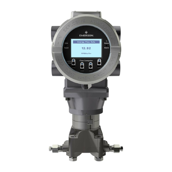
Software Tools ▪ RoHS2 Compliance The Emerson FB1200 Flow Computer measures pressure, differential pressure, and temperature for one or two meter runs of natural gas. This manual describes how to install and configure the Emerson FB1200 Flow Computer hardware. For information on using the FBxConnect ™... - Page 8 Emerson FB1200 Flow Computer Instruction Manual D301782X012 March 2019 Figure 1-1: FB1200 Flow Computer HMI module Front end cap (cover) Data plate Rear end cap (cover) Conduit fittings Enclosure Sensor module Introduction...
-
Page 9: Safety Labels
Failure to do so may result in injury to personnel or cause damage to the equipment. SAFETY FIRST General instructions and safety reminders. Features The FB1200 Flow Computer includes the following key features: Enclosure suitable for use in Class I Division 1 explosion proof and Ex db Zone 1 flame- proof ▪ environments Enclosure suitable for use in Class I Division 2 non-incendive and Ex nA Zone 2 non- sparking ▪... -
Page 10: Fb1200 Flow Computer Models
Application software supports AGA3, AGA8, ISO 5167, ISO 6976, and API 21.1 calculations in ▪ U.S., metric, or other natural gas standard units FB1200 Flow Computer Models You can purchase the FB1200 Flow Computer with or without integrated sensors. 1.3.1 FB1200 Flow Computer (with Multi-variable or Static Pressure Sensor) -
Page 11: Fb1200 Flow Computer (Without Integral Sensor)
128 MB FLASH Holds firmware image and configuration files Explosion-proof Enclosure The FB1200 Flow Computer includes an explosion-proof enclosure made of either aluminum or stainless steel. The enclosure consists of the main housing, two threaded covers, and four conduit entry points. -
Page 12: Physical Security
(cover). The FB1200 Flow Computer has North American certification for Class I Division 1 Groups C and D (explosion proof) and Class I Division 2 Groups A, B, C and D (non-incendive) hazardous locations or non-hazardous locations. -
Page 13: Power Options
Important Use only batteries supplied with the flow computer or sold by Emerson Remote Automation Solutions as spare parts for this flow computer. If you substitute a battery you obtain elsewhere you void your certification unless it is the identical part from the same manufacturer as that supplied with the flow computer from Emerson. -
Page 14: Communications
Emerson FB1200 Flow Computer Instruction Manual D301782X012 March 2019 Lead Acid Battery Pack ▪ 6.0 Vdc 4.5Ah ▪ Not suitable with ATEX or IECEx applications ▪ Can be optionally charged by a 6-watt solar panel ▪ Communications The flow computer includes three serial communication ports and one Ethernet port. The serial ports allow communication using DNP3, Modbus, BSAP, and ROC protocols. -
Page 15: Fbxwifi™ Communications
Emerson FB1200 Flow Computer Instruction Manual D301782X012 March 2019 Figure 1-5: HMI Module with LCD Figure 1-6: HMI Module without LCD Note If your flow computer does not include the LCD option, you still have the status LEDs and a single IR... -
Page 16: Software Tools
Emerson FB1200 Flow Computer Instruction Manual D301782X012 March 2019 1.11 Software Tools The FBxConnect configuration software provides a series of wizards that allow you to perform configuration activities for the flow computer. You connect a PC running the FBxConnect configuration software to the flow computer using one of the communication ports or through a wireless connection. -
Page 17: Section 2: Installation
Class I Division 2 installations; Appendix B contains special information for Class I Division 1 installations. For Europe the FB1200 Flow Computer has certifications for Ex db Zone 1 flame-proof and for Ex nA Zone 2 non-sparking installations and non-hazardous locations only. Appendix C... -
Page 18: Required Tools
Emerson FB1200 Flow Computer Instruction Manual D301782X012 March 2019 Table 2-1: Environmental Specifications Specification Range Ambient Temperature -40°C to +80 °C (-40 °F to +176 °F) - no battery, C1D1/C1D2 -40°C to +80 °C (-40°F to +176 °F) – lead acid battery, C1D1/C1D2 -40°C to +80 °C (-40 °F to +176 °F) –... -
Page 19: Fb1200 Flow Computer Dimensions - Multivariable Sensor Version
If your unit includes the optional FBxWifi, ensure the installation location provides line-of- ▪ sight access to the transceiver. Figure 2-1: FB1200 Flow Computer Dimensions – Multivariable Sensor Version (Option F1) Installation... -
Page 20: Fb1200 Flow Computer Dimensions (No Integral Sensor)
Emerson FB1200 Flow Computer Instruction Manual D301782X012 March 2019 Figure 2-2: FB1200 Flow Computer Dimensions – No Integral Sensor Version (Option F0) Installation... -
Page 21: General Wiring Guidelines
Emerson FB1200 Flow Computer Instruction Manual D301782X012 March 2019 Figure 2-3: FB1200 Flow Computer Dimensions – Static Pressure Sensor (Option F2) General Wiring Guidelines The flow computer’s pluggable terminal blocks use compression-type terminals. The 5.08 mm pitch terminal blocks accommodate wire between 28 and 12 AWG; the 3.81 mm pitch terminal blocks accommodate wire between 28 and 14 AWG. -
Page 22: Front Or Rear End Caps
Emerson FB1200 Flow Computer Instruction Manual D301782X012 March 2019 Front or Rear End Caps The flow computer includes two threaded covers (end caps). The front end cap includes a window for viewing the HMI module; the rear end cap provides access to the terminal plate for power and I/O wiring. -
Page 23: Removing The Front Or Rear End Caps
Emerson FB1200 Flow Computer Instruction Manual D301782X012 March 2019 Figure 2-6: Retaining Clamp and Screw 2.6.2 Removing the Front or Rear End Caps DANGER EXPLOSION HAZARD: Never remove end cap(s) in a hazardous location. Removing end cap(s) in a hazardous location could result in an explosion. -
Page 24: Replacing The Front Or Rear End Caps
Emerson FB1200 Flow Computer Instruction Manual D301782X012 March 2019 Unscrew the end cap turning it counter-clockwise until it comes off. Set it aside in a safe location. Figure 2-9: Front (left) and Rear (right) End Caps Removal 2.6.3 Replacing the Front or Rear End Caps DANGER EXPLOSION HAZARD: Ensure the area in which you perform this operation is non-hazardous. -
Page 25: Transmitter With Coplanar Flange
D301782X012 March 2019 Only use bolts supplied with the flow computer or sold by Emerson Remote Automation Solutions as spare parts. Refer to the figure for common flow computer assemblies with the bolt length required for proper flow computer installation. -
Page 26: O-Rings With Flange Adapters
Emerson FB1200 Flow Computer Instruction Manual D301782X012 March 2019 Carbon steel bolts do not require lubrication. Stainless steel bolts are factory-coated with a lubricant to ease installation. Do not apply any additional lubricant when installing either type of bolt. Finger-tighten the bolts. -
Page 27: Direct Mount
Emerson FB1200 Flow Computer Instruction Manual D301782X012 March 2019 Figure 2-14: O-rings with Flange Adapters Flange O-ring Square PTFE-based profile Round Elastomer profile Whenever the flange or adapters are removed, visually inspect the O-rings. Replace the O-rings if there are any signs of damage, such as nicks or cuts. -
Page 28: Traditional Flange Mounting Kit
Emerson FB1200 Flow Computer Instruction Manual D301782X012 March 2019 Figure 2-15: Traditional Flange Mounting Kit 2.0 in. pipe diam. U-bolt assembly (5/16-18 x 4.0 LG) with (2) nuts (item 3) Mounting bracket Apply Loctite ® 222™ Low Strength Purple Threadlocker to nuts. Torque nuts to 30 in-lbs (3.4 N m... -
Page 29: Indirect Mount
Emerson FB1200 Flow Computer Instruction Manual D301782X012 March 2019 Figure 2-16: Coplanar Mounting Kit Tubular L-shaped bracket 3/8-16 x 1 ½ in socket head wire lockable screw (2) – Apply Killark® LUBG-6 Thread Lubricant to threads. Torque screws to 30 in-lbs (3.4 N m) Split 3/8 lock washer (2) 5/16-18 keps nut (2). -
Page 30: Rotating The Housing
Emerson FB1200 Flow Computer Instruction Manual D301782X012 March 2019 Figure 2-17: Inline Mounting Kit Pipe mounting bracket U-bolt 2 ½ inch diam. pipe (5/16-18 x 3.75 long) 5/16 flat lock washer (2) 5/16-18 300 series hex nut (2) - Apply Loctite 222 Low Strength Purple Threadlocker to threads. - Page 31 Emerson FB1200 Flow Computer Instruction Manual D301782X012 March 2019 Figure 2-18: Housing Rotation Set Screw (1 each side) Set Screw (one each side) DANGER EXPLOSION HAZARD: Ensure the area in which you perform this operation is non-hazardous. Performing this operation in a hazardous area could result in an explosion.
-
Page 32: Grounding The Device
Emerson FB1200 Flow Computer Instruction Manual D301782X012 March 2019 Grounding the Device The flow computer includes a grounding lug on the terminal plate. Figure 2-19: Ground Lug Ground Lug DANGER EXPLOSION HAZARD: Ensure the area in which you perform this operation is non-hazardous. -
Page 33: Terminal Plate
Emerson FB1200 Flow Computer Instruction Manual D301782X012 March 2019 Terminal Plate The terminal plate includes the various terminal blocks (TB) for power and I/O connections. The terminal plate’s appearance varies depending upon whether you have the optional 6-channel expansion I/O module installed with 3.81 pitch connections; when it is installed there are eight or nine connections per terminal blocks instead of six 5.08 pitch connections. -
Page 34: Power Modes
Emerson FB1200 Flow Computer Instruction Manual D301782X012 March 2019 Terminal Plate (with Optional I/O with 8 3.81 mm Pitch Connectors) 2.10 Power Modes To keep power consumption to a minimum, especially for remote sites, the flow computer can run in two different power modes: Low Power Mode (4 or 8 MHz CPU clock speed) or Standard Power Mode (60 MHz CPU clock speed). - Page 35 Emerson FB1200 Flow Computer Instruction Manual D301782X012 March 2019 The local display (HMI module) with FBxWifi communications and WiFi uses additional power. You can configure it in FBxConnect to shut down after a period of inactivity. Table 2-4: Typical Power Usage – Low Power Mode at Room Temperature Description Power Usage (mW) at 6.1Vdc...
-
Page 36: Standard Power Mode
Emerson FB1200 Flow Computer Instruction Manual D301782X012 March 2019 2.10.2 Standard Power Mode When serial communication is active (other than to a remote 4088B MVT) the flow computer operates in standard power mode. The unit also uses standard power mode when: ▪... -
Page 37: Notes On Battery Life
Emerson FB1200 Flow Computer Instruction Manual D301782X012 March 2019 2.10.3 Notes on Battery Life Battery life varies based on numerous factors including temperature, communication usage, and various load options. To achieve the maximum battery life noted in the product data sheet requires that you: ▪... -
Page 38: Connecting Dc Power
Emerson FB1200 Flow Computer Instruction Manual D301782X012 March 2019 2.11.1 Connecting DC Power DANGER EXPLOSION HAZARD: Ensure the area in which you perform this operation is non-hazardous. Performing this operation in a hazardous area could result in an explosion. When power comes from an external DC supply, connect using the +DCIN and –DCIN terminals. -
Page 39: Connecting Battery Power
Emerson FB1200 Flow Computer Instruction Manual D301782X012 March 2019 2.11.2 Connecting Battery Power DANGER EXPLOSION HAZARD: Ensure the area in which you perform this operation is non-hazardous. Performing this operation in a hazardous area could result in an explosion. When power comes from an internal battery pack, the battery pack plugs into one of two connectors. -
Page 40: Installing The Optional Solar Panel
Emerson FB1200 Flow Computer Instruction Manual D301782X012 March 2019 2.12 Installing the Optional Solar Panel If you purchased the lead acid battery/solar panel kit for main power, you need to install the supplied 6W solar panel. If you purchased the lead acid battery with a solar regulator but you are supplying your own solar panel, follow the manufacturer’s instructions for remote mounting. - Page 41 Emerson FB1200 Flow Computer Instruction Manual D301782X012 March 2019 Figure 2-23: Attaching Mounting Hardware to the Solar Panel 6V, 6W solar panel aluminum tilt bracket (2) 10-32 x ½ pan head screw (4). Note: Matching hex nuts and washers not visible in this graphic;...
-
Page 42: Mounting The Solar Panel (Integral Mount)
Emerson FB1200 Flow Computer Instruction Manual D301782X012 March 2019 2.12.2 Mounting the Solar Panel (Integral Mount) DANGER EXPLOSION HAZARD: Ensure the area in which you perform this operation is non-hazardous. Performing this operation in a hazardous area could result in an explosion. - Page 43 Emerson FB1200 Flow Computer Instruction Manual D301782X012 March 2019 Figure 2-24: Integral Mounted Solar Panel 6V, 6W solar panel aluminum tilt bracket (2) 10-32 x ½ pan head screw (4). 5/16 flat washer (4); only two visible in this graphic 5/16-18 x .75 LG hex head bolt (2)
-
Page 44: Mounting The Solar Panel (Remote Mount)
Emerson FB1200 Flow Computer Instruction Manual D301782X012 March 2019 2.12.3 Mounting the Solar Panel (Remote Mount) DANGER EXPLOSION HAZARD: Ensure the area in which you perform this operation is non-hazardous. Performing this operation in a hazardous area could result in an explosion. -
Page 45: Connecting Solar Power
Emerson FB1200 Flow Computer Instruction Manual D301782X012 March 2019 2.12.4 Connecting Solar Power DANGER EXPLOSION HAZARD: Ensure the area in which you perform this operation is non-hazardous. Performing this operation in a hazardous area could result in an explosion. When power comes from a solar panel/lead acid battery combination, connect using the +SPIN and –SPIN terminals and standard copper wire (#18 AWG minimum). -
Page 46: Adjusting The Optional Solar Panel Tilt Angle
Emerson FB1200 Flow Computer Instruction Manual D301782X012 March 2019 2.12.5 Adjusting the Optional Solar Panel Tilt Angle DANGER EXPLOSION HAZARD: Ensure the area in which you perform this operation is non-hazardous. Performing this operation in a hazardous area could result in an explosion. -
Page 47: Connecting Communication Ports
Emerson FB1200 Flow Computer Instruction Manual D301782X012 March 2019 Table 2-6: Solar Panel Tilt Angle Latitude Installation Angle 0 to 4 10 from horizontal 5 to 20 Add 5 from the local latitude 21 to 45 ... - Page 48 Emerson FB1200 Flow Computer Instruction Manual D301782X012 March 2019 Figure 2-28: Connecting a Device to COM1 Using RS-232 RS-232 port (COM1) on FB device RS-232 port on external device When connecting COM1 to another device using RS-422, use wiring as shown in Figure 2-29.
- Page 49 Emerson FB1200 Flow Computer Instruction Manual D301782X012 March 2019 Figure 2-29: Connecting a Device to COM1 Using RS-422 RS-422 port (COM1) on FB device RS-422 port on external device When connecting COM1 to another device using RS-485, use wiring as shown in Figure 2-30.
-
Page 50: Connecting To Com2 And Com3
Emerson FB1200 Flow Computer Instruction Manual D301782X012 March 2019 Figure 2-30: Connecting a Device to COM1 Using RS-485 RS-485 port (COM1) on FB device RS-485 port on external device Regardless of the interface standard (RS-232, RS-422, or RS-485) you must use FBxConnect to configure the port for proper usage. -
Page 51: Connecting A Device To Com2 Or Com3 Using Rs-232 (With Optional I/O)
Emerson FB1200 Flow Computer Instruction Manual D301782X012 March 2019 Figure 2-31: Connecting a Device to COM2 or COM3 Using RS-232 (with Optional I/O) RS-232 port (COM2) on FB device RS-232 port (COM3) on FB device RS-232 port on external device Note COM3 does not have its own GND terminal. -
Page 52: Connecting A Device To Com2 Or Com3 Using Rs-232 (Without Optional I/O)
Emerson FB1200 Flow Computer Instruction Manual D301782X012 March 2019 Figure 2-32: Connecting a Device to COM2 or COM3 Using RS-232 (without optional I/O) RS-232 port (COM2) on FB device RS-232 port on external device RS-232 port (COM3) on FB device... -
Page 53: Connecting A Device To Com2 Or Com3 Using Rs-485 (With Optional I/O)
Emerson FB1200 Flow Computer Instruction Manual D301782X012 March 2019 Figure 2-33: Connecting a Device to COM2 or COM3 Using RS-485 (with optional I/O) RS-485 port (COM2) on FB device RS-485 port (COM3) on FB device RS-485 port on external device Note COM3 does not have its own GND terminal. -
Page 54: Ethernet Port
Emerson FB1200 Flow Computer Instruction Manual D301782X012 March 2019 Figure 2-34: Connecting a Device to COM2 or COM3 Using RS-485 (without optional I/O) RS-485 port (COM2) on FB device RS-485 port on external device RS-485 port (COM3) on FB device Regardless of the interface standard (RS-232 or RS-485), you must use FBxConnect to configure the port for proper usage. -
Page 55: Location Of Ethernet Port
Emerson FB1200 Flow Computer Instruction Manual D301782X012 March 2019 Figure 2-35: Location of Ethernet Port Ethernet Port Note If you ordered Ethernet, the unit ships with Ethernet enabled. If you need to operate the device in lower power mode, you must disable Ethernet. Jumper J10 on the CPU module (see... - Page 56 Emerson FB1200 Flow Computer Instruction Manual D301782X012 March 2019 Figure 2-36: Ethernet Port jumper Installation...
-
Page 57: Section 3: I/O Configuration And Wiring
Emerson FB1200 Flow Computer Instruction Manual D301782X012 March 2019 Section 3: I/O Configuration and Wiring This section covers the following topics: Analog Inputs ▪ ▪ Analog Outputs ▪ Digital Inputs Digital Outputs ▪ Pulse Inputs ▪ ▪ Connecting the RTD ▪... -
Page 58: Base I/O On Cpu (With Optional I/O)
Emerson FB1200 Flow Computer Instruction Manual D301782X012 March 2019 Figure 3-1: Base I/O on CPU (with Optional I/O) When wiring a 1-5 V Analog Input (AI), use configuration at left When wiring a 4-20 mA Analog Input (AI), use configuration at left... -
Page 59: Base I/O On Cpu (Without Optional I/O)
Emerson FB1200 Flow Computer Instruction Manual D301782X012 March 2019 Figure 3-2: Base I/O On CPU (without Optional I/O) When wiring a 1-5 V Analog Input (AI), use configuration at left When wiring a 4-20 mA Analog Input (AI), use configuration at left... - Page 60 Emerson FB1200 Flow Computer Instruction Manual D301782X012 March 2019 Figure 3-3: Optional 6-channel Expansion I/O Module When wiring a 1-5 V Analog Input (AI), use configuration at left When wiring a 4-20 mA Analog Input (AI), use configuration at left...
-
Page 61: Analog Inputs
Emerson FB1200 Flow Computer Instruction Manual D301782X012 March 2019 Analog Inputs The flow computer includes two on-board channels you can individually configure as either analog inputs (AI) or analog outputs (AO). In addition, if you purchased the optional 6-channel expansion I/O board, there are two additional channels you can individually configure as either AIs or AOs. -
Page 62: Ma Ai Wiring
Emerson FB1200 Flow Computer Instruction Manual D301782X012 March 2019 Figure 3-4: 4-20 mA AI Wiring (Base I/O with Optional I/O Module) Field Device Power Supply 30Vdc Max Figure 3-5: 1-5 V AI Wiring (Base I/O with optional I/O) Field Device... -
Page 63: Ai Wiring
Emerson FB1200 Flow Computer Instruction Manual D301782X012 March 2019 Figure 3-6: AI Wiring (Base I/O without Optional I/O Module) When wiring a 1-5 V Analog Input (AI), use configuration at left When wiring a 4-20 mA Analog Input (AI), use configuration at left... - Page 64 Emerson FB1200 Flow Computer Instruction Manual D301782X012 March 2019 Figure 3-7: 4-20 mA AI Wiring (with Optional 6-channel Expansion I/O Module). Field Device Power Supply 30Vdc Max Figure 3-8: 1-5 V Analog Input (AI) Wiring (Optional 6-channel Expansion I/O Module...
-
Page 65: Analog Outputs
Emerson FB1200 Flow Computer Instruction Manual D301782X012 March 2019 Analog Outputs The flow computer includes two on-board channels you can individually configure as either analog outputs (AO) or analog inputs. In addition, if you purchased the optional 6-channel expansion I/O board, there are two additional channels you can individually configure as either AOs or AIs. -
Page 66: Ao Wiring (Base I/O With Optional I/O)
Emerson FB1200 Flow Computer Instruction Manual D301782X012 March 2019 Figure 3-9: AO Wiring (Base I/O with Optional I/O) Field Device Power Supply 30Vdc Max Figure 3-10: AO Wiring (Base I/O without Optional I/O) Field Device Power Supply 30Vdc Max I/O Configuration and Wiring... -
Page 67: Digital Inputs
Emerson FB1200 Flow Computer Instruction Manual D301782X012 March 2019 Note Figure 3-11 shows analog output wiring for AIAO4. AIAO3 and AIAO4 share the same GND terminal. Figure 3-11: AO Wiring (with Optional 6-channel Expansion I/O Module) Field Device Digital Inputs Depending upon how you ordered it, the flow computer includes either two or six channels you can individually configure as digital inputs (DI), digital outputs (DO), or pulse inputs (PI). -
Page 68: Di Wiring
Emerson FB1200 Flow Computer Instruction Manual D301782X012 March 2019 3.3.1 DI Wiring The following figures show how to wire digital inputs. Note Figure 3-12 shows discrete input wiring for DIDO1. DIDO1 and DIDO2 share the same GND terminal. Figure 3-12: DI Wiring (Base I/O with Optional I/O) -
Page 69: Di Wiring (Base I/O -Without Optional I/O)
Emerson FB1200 Flow Computer Instruction Manual D301782X012 March 2019 Figure 3-13: DI Wiring (Base I/O without Optional I/O) Dry contact Note Figure 3-14 shows discrete input wiring for DIDO5. DIDO5 and DIDO6 share the same GND terminal. DIDO3 and DIDO4 share a different GND terminal. -
Page 70: Digital Outputs
Emerson FB1200 Flow Computer Instruction Manual D301782X012 March 2019 Digital Outputs Depending upon how you ordered it, the flow computer includes two or six channels you can configure as digital outputs (DO), digital inputs (DI) or pulse inputs (PI). Note When using a digital output to drive an inductive load (such as a relay coil), place a suppression diode across the load. -
Page 71: Do Wiring
Emerson FB1200 Flow Computer Instruction Manual D301782X012 March 2019 3.4.1 DO Wiring The following diagrams show how to wire digital outputs. Note Figure 3-15 shows digital output wiring for DIDO2. DIDO1 and DIDO2 share the same GND terminal. DIDO3 and DIDO4 share a different GND terminal. -
Page 72: Do Wiring (Base I/O Without Optional I/O)
Emerson FB1200 Flow Computer Instruction Manual D301782X012 March 2019 Figure 3-16: DO Wiring (Base I/O without Optional I/O) Power Supply 30Vdc Max 500 mA load max Note Figure 3-17 shows digital output wiring for DIDO4. DIDO3 and DIDO4 share the same GND terminal. -
Page 73: Pulse Inputs
Emerson FB1200 Flow Computer Instruction Manual D301782X012 March 2019 Pulse Inputs The flow computer includes two channels that can be individually configured as pulse inputs (PI), digital inputs (DI), or digital outputs (DO). When configured as pulse inputs, the PI channels have the following characteristics:... - Page 74 Emerson FB1200 Flow Computer Instruction Manual D301782X012 March 2019 Figure 3-18: PI Wiring (Base I/O with Optional I/O) Figure 3-19: PI Wiring (Base I/O without Optional I/O) I/O Configuration and Wiring...
-
Page 75: Connecting The Rtd
Emerson FB1200 Flow Computer Instruction Manual D301782X012 March 2019 Note Figure 3-20 shows pulse input wiring for PIDIDO5. PIDIDO5 and PIDIDO6 share the same GND terminal. PIDIDO3 and PIDIDO4 share a different GND terminal. Figure 3-20: PI Wiring (with Optional I/O Module) - Page 76 Emerson FB1200 Flow Computer Instruction Manual D301782X012 March 2019 Figure 3-21: Wiring for 2-Wire, 3-Wire, and 4-Wire RTD (Units with Optional I/O) 2-Wire RTD 3-Wire RTD 4-Wire RTD I/O Configuration and Wiring...
- Page 77 Emerson FB1200 Flow Computer Instruction Manual D301782X012 March 2019 Figure 3-22: Wiring for 2-Wire, 3-Wire, and 4-Wire RTD (Units without Optional I/O) 2-Wire RTD 3-Wire RTD 4-Wire RTD I/O Configuration and Wiring...
-
Page 78: Connecting A Rosemount 4088B Transmitter For Use In A Second Meter Run
Emerson FB1200 Flow Computer Instruction Manual D301782X012 March 2019 Connecting a Rosemount 4088B Transmitter for Use in a Second Meter Run Data for the second run comes from an external transmitter such as the Rosemount 4088B. Figure 3-23: Connecting a 4088B Transmitter for a Second Meter Run RS-485 bus, twisted pair required Enable AC termination using switches. - Page 79 Emerson FB1200 Flow Computer Instruction Manual D301782X012 March 2019 See the Rosemount™ 4088 Multivarible™ Transmitter Reference Manual (00809-0100-4088, Rev CB, Feb. 2017) for details on installing the 4088B. Using twisted pair wire, connect the RS-485 terminals for COM3 to the RS-485 terminals on the 4088B as shown in the graphic.
- Page 80 Emerson FB1200 Flow Computer Instruction Manual D301782X012 March 2019 I/O Configuration and Wiring...
-
Page 81: Section 4: Operation
▪ Establishing Communications ▪ Communicating using the HMI Module This section describes day-to-day operation of the Emerson FB1200 Flow Computer including how to turn it on and off and how to communicate with it. Powering Up/Powering Down the Device DANGER Do not attempt to connect or disconnect power from the unit in a hazardous area. -
Page 82: Communicating With A Laptop Using One Of The Serial Ports
Decide which communication protocol you will use. This could be DNP3, ROC, or BSAP. See these documents for more information: ▪ Emerson FB Flow Computer DNP3 Protocol Specifications Manual (D301806X012) ▪ ROC Protocol Specifications Manual (for Emerson FBx-series) (D301828X012) BSAP Communication Guide for FB1000/FB2000 Series Flow Computers (D301808X012) ▪... -
Page 83: Communicating With A Laptop Wirelessly With Fbxwifi
Emerson FB1200 Flow Computer Instruction Manual D301782X012 March 2019 EXPLOSION HAZARD: Ensure the area in which you perform this operation is non-hazardous. Performing this operation in a hazardous area could result in an explosion. Connect a Category 5 shielded cable between an Ethernet port on your laptop and an Ethernet switch for your network. -
Page 84: Communicating Using The Hmi Module
Emerson FB1200 Flow Computer Instruction Manual D301782X012 March 2019 Communicating using the HMI Module You must have purchased the flow computer with the HMI module version that includes the optional display. Not all models include the display. Units without the display still include a button to wake up the device and status LEDs. - Page 85 Emerson FB1200 Flow Computer Instruction Manual D301782X012 March 2019 Figure 4-2: Infrared (IR) Button Location Left Infrared (IR) Button Down Infrared (IR) Button Up Infrared (IR) Button Right Infrared (IR) Button Note When using the IR buttons, aim your finger at the round spot just below the arrow.
- Page 86 Emerson FB1200 Flow Computer Instruction Manual D301782X012 March 2019 Table 4-1: Infrared (IR) Buttons on HMI Module Button Mode ▪ Tap once to move up or down one item through list Screen Saver of parameters. ▪ Hold to stay on current parameter.
-
Page 87: Section 5: Service And Troubleshooting
Important Use only batteries supplied with the flow computer or sold by Emerson as spare parts for this flow computer. If you substitute a battery you obtain elsewhere you will void your certification unless it is the identical part from the same manufacturer as that supplied with the flow computer from Emerson. -
Page 88: Returning The Unit For Repairs
Other types of repairs cannot be performed in the field. In those cases, you must ship the unit to an Emerson-authorized repair facility. Contact Emerson Remote Automation Solutions for a return authorization number and instructions for where to ship the unit. -
Page 89: Interpreting The Status Leds
Emerson FB1200 Flow Computer Instruction Manual D301782X012 March 2019 WARNING International safety regulations restrict the shipment of lithium batteries. If you need to return the flow computer, remove the lithium battery before you ship the unit. Failure to remove the lithium battery may delay or prevent shipment of the flow computer. - Page 90 Emerson FB1200 Flow Computer Instruction Manual D301782X012 March 2019 Table 5-1: LED Descriptions Color/State Meaning An active wired Ethernet connection exists. Link LED GREEN Otherwise it is off. (FB1200/FB2200 only) Input LED GREEN One of the IR buttons is being pressed.
-
Page 91: Switch And Buttons
Emerson FB1200 Flow Computer Instruction Manual D301782X012 March 2019 5.3. Switch and Buttons A momentary switch and two push buttons on the HMI module provide trouble-shooting options for the flow computer. DANGER EXPLOSION HAZARD: Never remove end cap(s) in a hazardous location. Removing end cap(s) in a hazardous location could result in an explosion. -
Page 92: Replacing The Main Battery Pack
Emerson FB1200 Flow Computer Instruction Manual D301782X012 March 2019 Figure 5-3: Captive Fastening Screws Grasp the HMI module and remove it by gently pulling it straight out. To replace the HMI module, line up the printed circuit board (PCB) with the slot on the back and gently press it back on. - Page 93 Emerson FB1200 Flow Computer Instruction Manual D301782X012 March 2019 EXPLOSION HAZARD: Ensure the area in which you perform this operation is non-hazardous. Performing this operation in a hazardous area could result in an explosion. DANGER EXPLOSION HAZARD: Do not disconnect equipment unless power has been removed or the area is known to be non-hazardous.
-
Page 94: Removing/Replacing The Sram Battery
Emerson FB1200 Flow Computer Instruction Manual D301782X012 March 2019 Figure 5-5: Removing the Battery Pack Connect the new battery to the open connector. Route the wires so they are in the recessed area. Make sure the wires won’t get caught in the end cap threads. - Page 95 Emerson FB1200 Flow Computer Instruction Manual D301782X012 March 2019 DANGER Do not disconnect equipment unless power has been removed or the area is known to be non- hazardous. DANGER EXPLOSION HAZARD: Substitution of any components may impair suitability for Class I, Division 1 or Class I, Division 2.
-
Page 96: Upgrading System Firmware
D301782X012 March 2019 5.7. Upgrading System Firmware Periodically Emerson releases new system firmware for the flow computer to introduce new features or update system functions. You must know a valid username/password combination for the flow computer to complete this process. -
Page 97: Appendix A: Special Instructions For Class I Division 2 Locations
An RTD may be supplied with the Emerson FB1200 Flow Computer. Connection to the RTD is approved as a non-incendive circuit so that Division 2 wiring methods are not required. - Page 98 Emerson FB1200 Flow Computer Instruction Manual D301782X012 March 2019 Figure A-1: Data Plate (No Battery) – Class I Division 2 Non-incendive (UL) Special Instructions for Class I Division 2 Locations...
- Page 99 Emerson FB1200 Flow Computer Instruction Manual D301782X012 March 2019 Figure A-2: Data Plate (Lead Acid Battery) – Class I Division 2 Non-incendive (UL) Special Instructions for Class I Division 2 Locations...
- Page 100 Emerson FB1200 Flow Computer Instruction Manual D301782X012 March 2019 Special Instructions for Class I Division 2 Locations...
-
Page 101: Appendix B: Special Instructions For Class I Division 1 Locations
An RTD may be supplied with the Emerson FB1200 Flow Computer. Connection to the RTD is approved as a non-incendive circuit. - Page 102 Emerson FB1200 Flow Computer Instruction Manual D301782X012 March 2019 DANGER EXPLOSION HAZARD: Do not disconnect equipment unless power has been removed or the area is known to be non-hazardous. DANGER EXPLOSION HAZARD: Substitution of any components may impair suitability for Class I, Division 1 or Class I, Division 2.
- Page 103 Emerson FB1200 Flow Computer Instruction Manual D301782X012 March 2019 Figure B-1: Data Plate (No Battery) – Class I Division 1 Explosion Proof (UL) Special Instruction for Class I Division 1 Locations...
- Page 104 Emerson FB1200 Flow Computer Instruction Manual D301782X012 March 2019 Figure B-2: Data Plate (Lead Acid Battery) – Class I Division 1 Explosion Proof (UL) Special Instructions for Class I Division 1 Locations...
-
Page 105: Appendix C: Atex Non-Sparking Zone 2 Certifications
Emerson FB1200 Flow Computer Instruction Manual D301782X012 March 2019 Appendix C: ATEX Non-Sparking Zone 2 Certifications This appendix includes notes on ATEX certifications. For full details, please refer to the Emerson FB1200 Flow Computer Safe Use Instructions (D301769X012). Special Conditions of Use: Make provisions to ensure, in the event of transient disturbances, that the rated voltage does ▪... - Page 106 Emerson FB1200 Flow Computer Instruction Manual D301782X012 March 2019 Enclosure Rating: IP66 Terminal blocks for the FB1200 Flow Computer have the following characteristics: Terminal blocks can accommodate two conductors per channel. ▪ ▪ Stranded or solid wire allowed. ▪ Torque values: NM 0.5-0.6 Wire size: 28-12 AWG (0.08 –...
-
Page 107: Appendix D: Atex Flame-Proof Zone 1 Certifications
Emerson FB1200 Flow Computer Instruction Manual D301782X012 March 2019 Appendix D: ATEX Flame-Proof Zone 1 Certifications The data plate and certain conditions of use are shown below. For full details refer to the Emerson FB1200 Flow Computer Safe Use Instructions (D301769X012). - Page 108 Special Conditions of Use / Schedule of Limitations: Contact your authorized sales and service representative for any maintenance or repair ▪ beyond the routine maintenance of the FB1200 Flow Computer. Do not alter or disassemble any of the fireproof joints of the FB1200 Flow Computer. ▪...
-
Page 109: Index
Emerson FB1200 Flow Computer Instruction Manual D301782X012 March 2019 Index battery ..............33 DC power ............32 4088B transmitter ........... 73 Ethernet .............. 49 I/O ............... 51 ports ..............41 Analog Inputs ............55 power ..............31 Analog Outputs ............59 RTD .............. - Page 110 RS-485 ............. 44 Pressure Version) ..........4 2-31. Connecting a Device to COM2 or COM3 1-3. FB1200 Flow Computer (No Integral Sensor) ... 5 Using RS-232 (with Optional I/O) ..... 45 1-4. Retaining Clamps and Tie Holes for Tamper- 2-32. Connecting a Device to COM2 or COM3 resistant Seals .............
- Page 111 Emerson FB1200 Flow Computer Instruction Manual D301782X012 March 2019 3-18. PI Wiring (Base I/O with Optional I/O) ..69 Mounting 3-19. PI Wiring (Base I/O without Optional I/O ..69 direct ..............21 3-20. PI Wiring (with Optional I/O Module) ... 70 indirect ..............
- Page 112 Standard Power Mode ..........30 Symbols on LCD display ............76 Tables 1-1. Memory ............5 1-2. FB1200 Flow Computer I/O Configurations ..7 1-3. Power Options..........7 1-4. Serial Ports ............8 2-1. Environmental Specifications ......12 2-2. Required Tools ..........12 2-3.
- Page 113 Emerson FB1200 Flow Computer Instruction Manual D301782X012 March 2019 Index...
- Page 114 Emerson Automation Solutions Remote Automation Solutions Emerson FZE P.O. Box 17033 © 2018-2019 Remote Automation Solutions, a business unit of Emerson Automation Jebel Ali Free Zone – South 2 Solutions. All rights reserved. Dubai U.A.E. This publication is for informational purposes only. While every effort has been made to ensure...