
Related Manuals for Samsung SCX-6320F/XEC


Summary of Contents for Samsung SCX-6320F/XEC
-
Page 1: Table Of Contents
DIGITAL LASER MFP SCX-6320F/XEC Basic Model : SCX-6320F SERVICE Manual DIGITAL LASER MFP CONTENTS 1. Precautions 2. Reference Information 3. Specifications 4. Summary of product 5. Disassembly and Reassembly 6. Alignment and Adjustments 7. Troubleshooting 8. Exploded Views and Parts List 9. -
Page 2: Precautions
High voltages and lasers inside this product are dangerous. This printer should only be serviced by a suitably trained and qualified service engineer. (2) Use only Samsung replacement parts There are no user serviceable parts inside the printer. Do not make any unauthorized changes or additions to the printer, these could cause the printer to malfunction and create electric shock or fire hazards. -
Page 3: Caution For Safety
Take care not to cut or damage the power cable or plugs when moving the machine. (9) Use caution during thunder or lightening storms. Samsung recommend that this machine be disconnected from the power source when such weather conditions are expected. Do not touch the machine or the power cord if it is still connected to the wall socket in these weather conditions. -
Page 4: Handling Precautions
1.2.4 Assembly / Disassembly Precautions Replace parts carefully, always use Samsung parts. Take care to note the exact location of parts and also cable routing before dismantling any part of the machine. Ensure all parts and cables are replaced correctly. -
Page 5: Disregarding This Warning May Cause Bodily Injury
Failure to do so could cause the printer to tip or fall possibly causing personal injury or damaging the printer. (5) Do not install the printer on a sloping or unstable surface. After installation, double check that the printer is stable. Service Manual Samsung Electronics... -
Page 6: Esd Precautions
2. Be sure to replace the battery with the same or equivalent type recommended by the manufacturers. 3. Super capacitor or Lithium batteries contain toxic substances and should not be opened, crushed, or burned for disposal. 4. Dispose of used batteries according to the manufacturer’s instructions. Service Manual Samsung Electronics... - Page 7 Precautions MEMO Service Manual Samsung Electronics...
-
Page 8: Reference Information
• Spring Hook Standard : For general use • Tweezers Standard : For general home use, small type. • Cotton Swab Standard : For general home use, for medical service. • Software (Driver) installation CD ROM Service Manual Samsung Electronics... -
Page 9: Acronyms And Abbreviations
Second Cassette Feeder FCOT First Copy Out Time SMPS Switching Mode Power Supply FPOT First Print Out Time SPGP Samsung Printer Graphic Processor firmware Samsung Printer Language graphics device interface Spool Simultaneous Peripheral Operation Online ground Switch Host Based Printing... -
Page 10: Service Parts
ELA=Electrical Assembly, HOU =Housing MEA UNIT-COVER PA EXIT ASS’Y MEA= Mechanical Assembly, PA=Paper PMO-TRAY EXTENTION MP NE PMO= Processing Mold MP=Multi-Purpose(Bypass) tray NE=for NEC (common as Samsung Halk printer) MEC-CASSETTE ASS’Y(LETTER) MEC = Mechanic Combined unit COVER-M-FRONT M=Mold MPR-NAME/PLATE MPR= Machinery Press,... - Page 11 PMO-GUIDE DP SIDE DP=Duplex RING-CS CS= Compress GEAR-MP/DUP DRV MP =Multi-Purpose (Bypass) tray DUP DRV = Duplex Driver IPR-BRKT G DUPI PR=Iron Press BRKT=BRACKET G= Ground DUP=Duplex PMO-BUSHING TX(B4) TX=Transmit PMO-TRAY CASE, MP MP=Multi-Purpose tray(Bypass tray) Service Manual Samsung Electronics...
- Page 12 PBA SUB-MP-SEN =>Sub Printed circuit Board Assembly for the MP-SEN(= Multi-Purpose (Bypass) tray-Sensor) A/S MATERAL-PICKUP,MP FOOT-ML80 HOLDER CATCH CST MC2 MC2=>McKInley2 (Samsung Project code name) IPR-GROUND PLATE A(OPC) OPC=Organic Photo-Conductive ELA M/M-AUD SPEAKER ELA M/M => Electrical Assembly M/M AUD=Audio...
- Page 13 REGI=Registration PBA SUB-REGI PBA SUB-REGI => Sub Printed circuit Board Assembly for the Registration GROUND-P_SCAN ROLLER GROUND-P =Ground-Press IPR-GUARD C/O S/W C/O = Cover Open S/W= Switch MEA UNIT-TX STACKER TX =Transmit IPR-WASHER SPRING CU CU=Curve Service Manual Samsung Electronics...
-
Page 14: The Sample Pattern For The Test
The sample pattern shown in below is the standard pattern used in the factory. The life of the toner cartridge and the printing speed are measured using the pattern shown below. (The image is 70% of the actual A4 size). 2.3.1 A4 5% Pattern Service Manual Samsung Electronics... - Page 15 Reference Information 2.3.2 A4 2% Pattern Service Manual Samsung Electronics...
-
Page 16: A4 Iso 19752 Standard Pattern
Reference Information 2.3.3 A4 ISO 19752 Standard Pattern This test page is reproduced at 70% of the normal A4 size Service Manual Samsung Electronics... -
Page 17: Wireless Lan
The most of main wireless networking companies are attending and the main companies are Lucent technologies, Cisco, Intel/Symbol, 3Com, Enterasys (Cabletron), Compaq, IBM, Nokia, Dell, Philips, Samsung elec- tronic, Sony, Intersil, and so on. This mark certifies mutual compatibility among product has Wi-Fi (IEEE 802.1) and it is certified as a standard of... - Page 18 Reference Information MEMO Service Manual 2-11 Samsung Electronics...
-
Page 19: Specifications
Pentium IV 1.2 Ghz, 128 MB RAM, 220MB(Hard Disk) Minimum System Requirement Pentium III 500Mhz, 32 MB RAM, 100MB(Hard Disk) 20 characters X 2 lines with Backlight Memory 4 Mbyte for flash Memory , 32 Mbyte SDRAM * Sound Pressure Level, ISO 7779 Service Manual Samsung Electronics... -
Page 20: Print Specification
Data coding(Compression) MH/MR/MMR/JBIG/JPEG(Color/Transmission) Modem speed 33600/28800/21600/19200/14400/12000 Transmission Speed Approximately 3 sec(33,600 bps) Effective Scanning Width 8.2 inches(208 mm) Halftone 256 Levels Paper Capacity(Input) DADF(Duplex Automatic Document Feeder) : 50Sheets(75g/m2) FAX Mode Standard /Fine/Super Fine/Halftone Memory 16MB Service Manual Samsung Electronics... -
Page 21: Scanner Specification
Platen : 25 ~ 400%(1% Step) ADF : 25~100 %(1% Step) NOTE : (1) Speed claims based on the test chart : Letter size. SDMP : Single Document Multiple Printout MDSP : Multiple Document Single Printout Service Manual Samsung Electronics... - Page 22 * Toner Cartridge Yield : Average cartridge yield 8,000 standard pages Declared yield value in accordance with ISO / IEC 19752. 3.8 Maintenance Items Description Fuser Unit 100,000 images Transfer Roller 100,000 images Paper Feeding Roller 100,000 feeds DADF Feed Roller 50,000 feeds DADF Rubber Pad 20,000 feeds Service Manual Samsung Electronics...
-
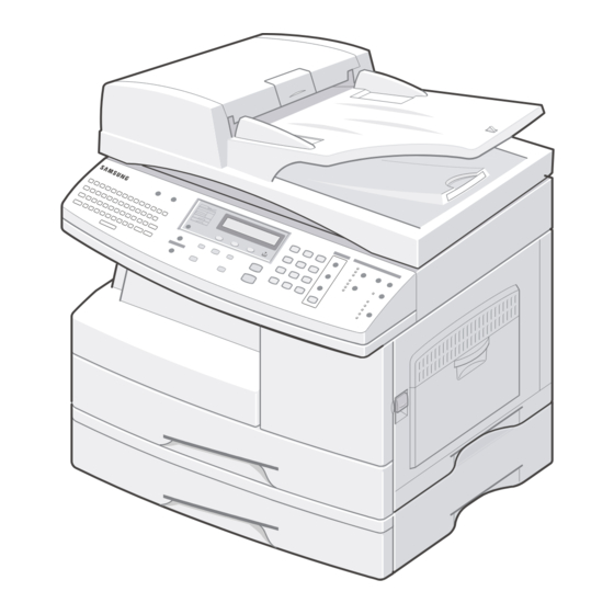
Page 23: Summary Of Product
Summary of Product 4. Summary of Product This chapter describes the functions and operating principles of the main components. 4.1 Printer Components 4.1.1 Front View Service Manual Samsung Electronics... -
Page 24: Rear View
Summary of Product 4.1.2 Rear View * The network port is not fitted as standard on the machine. ** If your country has a different telephone connection system, this socket may be blocked. Service Manual Samsung Electronics... - Page 25 Summary of Product 4.1.3 Control Panel (SCX-6320F & SCX-6220) Service Manual Samsung Electronics...
- Page 26 Summary of Product Service Manual Samsung Electronics...
- Page 27 Summary of Product Service Manual Samsung Electronics...
-
Page 28: System Layout
The two motors are, like the printer drive motors, used to feed the paper through the ADF mechanism. The ADF duplex motor is used for reversing the paper feed for double sided originals. Both DADF motors operate a a maximum of 2940pps. Service Manual Samsung Electronics... -
Page 29: General Specification
• CCD Image sensor uses +5V Power and Inverter uses +24Vpower. - CCD Max. Driving Frequency : 10MHz - CCD Line time : 0.68ms - White Data Output Voltage : 0.7V°æ0.5V (Mono Copy, 0.68ms/line) - Maximum Inverter Current : 600 mA Max.(Power +24V) Service Manual Samsung Electronics... - Page 30 To remove document jam in feed area Exit Open Sensor To remove document jam in exit area 4.2.6.3 DADF Rubber Material SI rubber Life 20,000 sheets (A4 standard) 4.2.6.4 DADF Roller Diameter 25.06mm Material EPDM Life 50,000 sheets (A4 standard) Service Manual Samsung Electronics...
- Page 31 Valid Scan Width 210 mm Max Scan Width 216 mm Scan Line Characteristic Scan line curvature under 1.0 mm Scan line inclination under 1.0 mm Sync Detecting position 121.7 mm Sync PULSE Width 1 u sec or more Service Manual Samsung Electronics...
- Page 32 Store CRU cartridges in a location that is not subject to rapid changes in temperature or humidity. 4.2.8.1 Toner Cartridge Specification The Toner CRU has a CRUM to enable the firmware to differentiate Samsung and third party versions as well as detect CRU presence.
- Page 33 Summary of Product 4.2.8.1.1 CRUM for Toner cartridge Branded Samsung toner cartridges must be used in the SCX6220/6320F. The Usage data saved in the CRUM are either used by other features or are printed on the billing / counters list.
- Page 34 ] button repeatedly, then Select [Billing/Counters]. Push the [Enter] key <in Tech mode> Push [menu] button, then Select the number [6] key. Push [ ] or [ ] button repeatedly, then Select [Billing/Counters]. Push the [Enter] key Service Manual 4-12 Samsung Electronics...
- Page 35 (customer usage assumption). This data is printed only in Tech mode. * Vendor : SAMSUNG( xxxxxx ) [ xxx ] Vendor name of the machine : example [EXP] Vendor name of the toner cartridge (CRUM) : Example (EXPORT) If the vendor name of the toner cartridge (CRUM) corresponds to the vendor name of the machine, the machine works normally.
-
Page 36: System Description
Main Board MODEM Scan Module USB2.0 Flash Image (PCL6) Sensor IEEE1284 SDRAM Flash Network I/F Kit (basic oper ating code) Network I/F SRAM (User Settings) Motor Flash Driver Option Memory SDRAM/ Motors sensors Flash Rom (PS3)/Fonts Service Manual 4-14 Samsung Electronics... -
Page 37: Main Controller
It stores the system program, this can be updated by downloading the system program through the PC Interface. It is also used to store the FAX Journal, One Touch Dial and Speed Dial lists. • Capacity :4M Byte • Access Time :70 nsec Service Manual 4-15 Samsung Electronics... - Page 38 - A battery backup power supply is used to ensure faxes stored in memory are not lost when power is off. 4.3.2.4 System Data Memory (SRAM) This memory is used to store client settings and operation variables. It has a battery supply to maintain values when power is off. Service Manual 4-16 Samsung Electronics...
- Page 39 This Flash Memory stores the NPC Firmware which controls the entire Network Protocol and software for Embedded Web Service & Network Management. This Flash Memory can be upgraded through Network by using the EWS (Embedded Web Server) or SyncThru Management software. Service Manual 4-17 Samsung Electronics...
- Page 40 Whilst the NPC card is capable of supporting the Wireless interface module this is not implemented in SCX6220/6320F. 11) 80 pin Connector This connector passes all of the electrical signal required for communication between the Main PBA and the NPC. This comprises Address Bus, Data Bus, Control Bus and Power signals. Service Manual 4-18 Samsung Electronics...
- Page 41 The PS ROM is connected to the ROM BUS of the CPU (SPGPm) on the Main PBA and provides PostScript3 support. This FLASH Memory can be upgraded using the RCP (Remote Control Panel) or EWS (Embedded Web Server). Postscript support is an optional feature purchased separately. Service Manual 4-19 Samsung Electronics...
-
Page 42: Fax Features
Automatic reduction operation, the memory has to have a capability to receive a one-page image data completely. Sometimes if the image data is bigger than the memory capacity, for example, full image with Superfine Photo res- olution, the image cannot be received. Service Manual 4-20 Samsung Electronics... - Page 43 Each page is only deleted when the set is certain that the page print is successful. For this reason there may be times when less memory is available than is required to receive a complex page image. Service Manual 4-21 Samsung Electronics...
-
Page 44: Receive Mode
Receive poll can be reserved for up to 50 Transmission jobs. The user can add documents to a Delayed, or Polling transmission previously reserved in the SCX-6320F's memory. Also the user can cancel reserved jobs. Service Manual 4-22 Samsung Electronics... -
Page 45: Disassembly And Reassembly
4. Use a flat and clean surface. 5. Replace only with authorized components. 6. Do not excessive force on components made of plastic, they may break. 7. Make sure all components are in their proper position. Service Manual Samsung Electronics... -
Page 46: Rear Cover
LIU harness. Release the plastic supporting clip - Rear Cover (see page 5-1) and remove the LIU 2. Remove the screw securing the Cover Panel MFP Screw Screw LIU Harness LIU Harness Screw Screw Supporting Clip Supporting Clip Service Manual Samsung Electronics... -
Page 47: Rear Cover (See Page
When closing the doors the front door must be closed before the side door. Open the front and side doors to gain access to the screws in the following steps. Front Cover Side Cover Ass'y Service Manual Samsung Electronics... - Page 48 8. Open the DADF Ass’y in the direction of arrow. Pull the DADF Ass'y upward and remove it. Scanner Ass'y 9. Remove the three screws securing the Platen Ass'y. 7. Remove the DADF Main Cable. DADF Main Cable Clips Service Manual Samsung Electronics...
- Page 49 Notice : Dust or other foreign matter can cause the module to jam or image quality to deteriorate. Only open the scanner in a clean environment and ensure all parts are clean when reassembling the scanner. Service Manual Samsung Electronics...
- Page 50 17. Release the belt from the underside of the scanner module. Unclip the Shaft CCD and take out the 15. Remove the five screws securing the Cover Dummy Scanner Module. Lower and remove it. CCD Cable Cover Dummy Lower Cover Scan Lower Service Manual Samsung Electronics...
- Page 51 Scanner Module Notice : Take care when reassembling the scanner module to the belt. The CCD Module should be located just to the right of the belt tension spring as shown below. Scanner Module Spring Belt Service Manual Samsung Electronics...
-
Page 52: Scanner Ass'y (See Page
5. Remove the TX Stacker 3. Remove the one screw securing the COVER-M-FRONT and unlatch the COVER-M-FRONT using a flat-blade screwdriver, as shown below. Then pull the COVER-M- FRONT upward and remove it. COVER-M-FRONT TX Stacker Ass’y Platen Cover Ass’y Service Manual Samsung Electronics... - Page 53 Ass'y. Look under the edge of the Support Pickup screw securing the ground cable. Ass’y and release the spring from the Pickup Ass’y. Then remove the Support Pickup Ass’y, as shown below. DADF SUB Ass’y Support Pickup Ass’y Gate Sensor Spring- Roller Holder Service Manual Samsung Electronics...
- Page 54 11. Unplug the Open Cover Sensor connector and Guide Pickup Ass’y remove the Open Cover Ass'y in the direction of arrow. Then release the harness, as shown below. Width Sensor Open Cover Ass’y Doc Sensor Open Cover Sensor Service Manual 5-10 Samsung Electronics...
- Page 55 17. Unplug the one connector and three screws securing the Duplex Motor Ass'y and remove it. Duplex Motor Ass'y 15. Remove the three screws securing the Cover Gear and remove it, as shown below. Cover Gear Service Manual 5-11 Samsung Electronics...
- Page 56 Contact Rubber OPE Sub 5. Remove the Key Pad from the unit. FPC Cable 3. Remove ten screws securing the OPE Main PBA and the LCD Module from the OPE Cover Key Pad Main PBA Service Manual 5-12 Samsung Electronics...
- Page 57 E-MAIL UNIT Key Plate 7. Remove the five screws securing the E-MAIL Option 9. Remove the Email Rubber and Key Pad from the unit. PBA and remove it. COVER-M-EMAIL E-MAIL PBA E-mail Rubber Key Pad Service Manual 5-13 Samsung Electronics...
- Page 58 Tray Links from the slot in the Tray Case. MP Tray 2. Lift hinge to release it and then slide the Side Cover Ass’y towards the front to release hinge and lift out the cover. Tray-Case Tray Link Side Cover Ass'y Service Manual 5-14 Samsung Electronics...
- Page 59 1. Release 4 clips (2 each side – 1 black and 1 white). 1. Release the colored plastic bushes at each end of the Then lift the Duplex Ass’y away from the Side Cover. Transfer Roller and lift the roller out, as shown below. Duplex Ass’y Service Manual 5-15 Samsung Electronics...
-
Page 60: Side Cover Ass'y (See Page
- Side Cover Ass'y (see page 5-13) 2. Remove the one screw and take out the Cover Sheet Connector. Cover Sheet Connector 5. Remove the two screws and take out the Thermostat. Thermostat 3. Unplug the one connector. Service Manual 5-16 Samsung Electronics... - Page 61 2. Remove two screws and Cover Paper Exit Ass'y, as should remove: shown below. - Rear Cover (see page 5-2) - LIU PBA (see page 5-2) Cover Paper Exit Ass’y - Scanner Ass'y (see page 5-3) Service Manual 5-17 Samsung Electronics...
- Page 62 (Main Motor : 10 pin, Duplex Motor : 4 pin) Dust Fan 4. Remove four screws (2 screws securing ground wires and 1 screw securing the Zener PBA) and take out the Drive Ass'y. taking care not to damage the Zener PBA. Driver Ass'y Service Manual 5-18 Samsung Electronics...
-
Page 63: Exit Ass'y (See Page
- LIU PBA (see page 5-2) - Scanner Ass’y (see page 5-3) - Cover Paper Exit Ass’y(see page 5-17) 2. Remove three screws and take out the Shield SMPS Upper. 4. Remove the SMPS, as shown below. SMPS Service Manual 5-19 Samsung Electronics... -
Page 64: Cover Exit Rear
- Scanner Ass’y (see page 5-3) - Exit Ass'y (see page 5-17) - Cover Paper Exit Ass’y(see page 5-17) - SMPS (see page 5-19) 2. Remove the one screw and take out the Panel Connect MPF. Service Manual 5-20 Samsung Electronics... -
Page 65: Lsu (See Page
5. Remove the seven screws and take out the Main Frame Ass'y. Dummy Base Frame Main Frame Ass’y Cam Jam Remove Front Cover 3. Remove the Lock Deve, and then remove one screw and the Cover Motor Bracket. Cover Motor Bracket Lock Deve Service Manual 5-21 Samsung Electronics... - Page 66 2. Unplug the two connectors. 5. Release two hooks underneath the frame. Pull the MP Ass'y upward and remove it. MP Ass'y 3. Remove the one screw and take out the Dummy Dummy Cover Cover. Service Manual 5-22 Samsung Electronics...
- Page 67 - Exit Ass’y (see page 5-17) - Cover Paper Exit Ass’y(see page 5-17) - LSU (see page 5-20) - Main Frame Ass’y (see page 5-21) - MP Ass’y(see page 5-22) 2. Remove the three screws. MP Ass'y Service Manual 5-23 Samsung Electronics...
-
Page 68: Service Manual
(white plastic clip) and take out the Pick Up Ass'y, as shown below. 3. Remove the two screws and take out the Cassette Rail. Guide Paper Out Pick-up Ass’y IPR-Gnd Input Ground Screw Cassette Rail Service Manual 5-24 Samsung Electronics... -
Page 69: Main Pba
Take out the Shield Main taking care to ease the power socket from the LH frame. Shield Main Lower 4. If fitted release the plastic support securing the NPC PBA to the Main PBA NPC PBA Main PBA Service Manual 5-25 Samsung Electronics... - Page 70 Precautions MEMO Service Manual 5-26 Samsung Electronics...
-
Page 71: Alignment And Adjustments
6. Alignment and Adjustments This chapter describes some of the main service procedures including: Using the Tech Mode; Clearing paper jam and test patterns. Much of this chapter is also included in the user's guide. 6.1 Paper path Service Manual Samsung Electronics... -
Page 72: Clearing Paper Jams
This could damage the internal mechanism causing print quality problems or possibly electrical shock. Fault Clearance When a fault occurs, check the Status Map on the Control Panel. A green blanking LED identifies the problem area: Service Manual Samsung Electronics... -
Page 73: Clearing Document Jams
DADF. NOTE : To prevent document jams, use the document scanner glass for thick, thin or mixed docu- ments. 2) Pull the document gently to the right and out of the DADF. Service Manual Samsung Electronics... - Page 74 3) Close the document cover. Then place the documents back into the DADF. 2) Seize the misfed document, and remove the document from the DADF or the feed area by carefully pulling it towards the right using both hands. Service Manual Samsung Electronics...
-
Page 75: Paper Jams
“Paper and fully insert the paper tray. Jam0” message on the display. If there is any resistance, and the paper does not move immediately when you pull, stop pulling. Then continue to step3 Service Manual Samsung Electronics... -
Page 76: Fuser Area
Exit Area. 4) Push the fuser lever up, and then close the side cover. NOTE: Do not pull paper up through the fusing unit. Unfused toner may adhere to the area, result- ing in smudged copies. Service Manual Samsung Electronics... -
Page 77: Paper Exit Area
7) Close the front cover (1) and the side cover (2). 4) Turn the Jam Remove Lever in the direction of the arrow to move the paper to the exit area, then gen- tly pull the paper out through the exit area. Service Manual Samsung Electronics... -
Page 78: Duplex Jam
2) Remove the paper in the direction shown. To completely, lift the front part of the Tray slightly up avoid the paper torn, pull it out gently and slowly. to release the Tray from the machine Service Manual Samsung Electronics... -
Page 79: User Mode
[Off] [Off] Change Default [Left Page] Book Copy [Right Page] [Both Pages] Auto Suppress [Off, On] [Off] [Off] [Off] [Front] [Tray 1] Covers [Back] [Tray 1] [Front&Back] [Tray 1] [Off] [Off] Transparencies [ MP Tray] [Off] Service Manual Samsung Electronics... - Page 80 Email Tx Report Fax Phone Book Junk Fax List Billing/Counters Connect Page User Auth List Netscan Journal Print All Reports 7.Sound/Volume Speaker [On, Off, Com] Ringer [Off, Low,Med,High] Key Sound [On, Off] Speaker Alarm Sound [On, Off] Service Manual 6-10 Samsung Electronics...
- Page 81 Clear Memory [Email Address Book] [Email TX History] [Netscan Journal] Billing Counters [Serial Number] [Adjust Shading] Maintenance [Clean Drum] [New Drum] [Notify Toner Low] [Create] Mailbox Setup [Delete] Fax/Email Forward Setup Forward Netscan Timeout Timeout Period Service Manual 6-11 Samsung Electronics...
-
Page 82: Tech Mode
[ 1 ] : LSU diagonostic [ 2 ] : Sensor(Actuator)diagonostic [ 3 ] : SCF diagonostic [ 4 ] : CRU diagonostic [ 5 ] : Circuit test for Xerographic processing [ 6 ] : Auto test Service Manual 6-12 Samsung Electronics... - Page 83 Go to the next test (go to AIR TEMP CHECK) Read and display the temperature of the current working environment. NEXT AIR TEMP CHECK CHECK Go to the next test (go to OPC FUSE STATE) - Display the ADC value Service Manual 6-13 Samsung Electronics...
- Page 84 PTL CONTROL Auto TEST FAN CONTROL FUSER CONTROL Automatic Test Sequence LSU MOTOR CONTROL LASER DIODE CONTROL SENSOR DETECT MHV CONTROL DEV CONTROL THV NEG CONTROL THV CONTROL MHV ADC READ THV ADC READ TEST END Service Manual 6-14 Samsung Electronics...
- Page 85 Alignment & Adjustments 6.4.1.3 Operation of Tech mode Service Manual 6-15 Samsung Electronics...
-
Page 86: Data Setup
Brazil France Oman Italy Poland Spain Bangladesh Austria Kuwait Netherlands Moroco Belgium Algeria Country Portugal Pakistan Sweden Norway Bahrain Denmark Srilanka Finland Saudi Arabia Switzerland Chile Greece Peru Ireland Argentina Turkey Hungary Romania Bulgaria Czech Service Manual 6-16 Samsung Electronics... -
Page 87: Machine Test
3. After scanning the CCD SHADING PROFILE will be print out. 4. If the printed image is different to the sample image shown the CCD is defective. NOTICE : When you test the CCD, make sure that the cover is closed. Service Manual 6-17 Samsung Electronics... - Page 88 If a communication error occurs while the machine is in TECH mode, the protocol list will print automatically. 6.4.5.2 System Data List This list provides a list of the user system data settings and tech mode settings. Service Manual 6-18 Samsung Electronics...
- Page 89 Platen Scan Page Count : 27 Replaced Toner Count Replaced Drum Count Equivalent Drum Revolution Rate : 126.10% (2237) (Projected Page Counts) CRUM Information Vendor : SAMSUNG(China) [CHN] Capacity : 8K Product Date : 2004.06 Install Date : 2004.01.04 Serial...
-
Page 90: Flash Upgrade
1. The Sending and Receiving fax machines MUST be the same model. 2. The sending fax must be set up in ECM mode and the Receiving fax memory must be 100%. If not the function will not work. Service Manual 6-20 Samsung Electronics... - Page 91 -> type your machine ip address in address field. -> Maintenance Tab -> Firmware Upgrade -> Fill file path and name in File name field. -> Press "Upgrade" button Upgrading NIC F/W will take at least one minute. Service Manual 6-21 Samsung Electronics...
-
Page 92: Abnormal Image Printing And Defective Roller
Black spot Supply Roller 43.80mm Horizontal density band Develop Roller 54.30mm Horizontal density band Transfer Roller 56.60mm Black side contamination/transfer fault Heat Roller 83.60mm Black spot and fuser ghost Pressure Roller 91.00mm Black side contamination Service Manual 6-22 Samsung Electronics... - Page 93 Thermister is not *Please test the fuser in engine test mode. connected to the main board or contact *If the problem still persists, replace fuser unit. points are loose or dirty. Service Manual 6-23 Samsung Electronics...
- Page 94 CRUM terminals in the cartridge are dirty then check CRUM contact points. (Try or loose. uninstalling and re-installing the cartridge) Invalid Cartridge The toner cartridge is not for the Samsung Check that the toner cartridge is correct for machine. this model. DRUM WARNING...
- Page 95 Or, when setting up machine loaded with the original document. to poll another fax machine, you have used an Enter the correct poll code. incorrect poll code. Service Manual 6-25 Samsung Electronics...
- Page 96 Address Book Full Display when the Address book is full when trying to If address book is full then you must delete add a new entry. unused address before trying to add new addresses. Service Manual 6-26 Samsung Electronics...
- Page 97 The toner cartridge has run out. The machine stops. Replace Toner Toner Low Take out the toner cartridge and gently shake it. The toner is almost empty. By doing this, you can temporarily reestablish printing operations. Service Manual 6-27 Samsung Electronics...
-
Page 98: Troubleshooting
• Check the right position of the Scanner disturbance. Motor, and check the any mechanical dis turbance in the CCD carriaging part. • Check the Motor Driver in Driver PBA. • If any driver is defective, replace it. Service Manual Samsung Electronics... - Page 99 • Check the right position of the Scanner disturbance. Motor, and check the any mechanical disturbance in the CCD carriaging part. • Check the motor driver in Driver PBA. • If any driver is defective, replace it. Service Manual Samsung Electronics...
- Page 100 LIU PBA. • Replace LIU PBA. Replace main PBA. Defective automatic fax • Is the ring checked? • Replace LIU PBA if it cannot be checked. reception • Refer to ‘Defective Transmission.’ • Refer to ‘Defective Transmission’. Service Manual Samsung Electronics...
-
Page 101: Print Quality
Digital Printer 4. Lower bias voltage Digital Printer 5. Contamination of high voltage contact. 5. Leakage toner cause bad contact and Digital Printer increase contact resistance. Clean contami- Digital Printer nated area. 6. Transfer volatge and roller. Service Manual Samsung Electronics... - Page 102 1. Clean the transfer roller with vacuum cleaner. paper 2. Stains of paper path. 2. Clean the area of paper path with cloth or air cleaner. 3. Remove fuser and replace it. 3. Pressure roller’s contamination. Service Manual Samsung Electronics...
- Page 103 2. Charge roller’s contamination 2. Clean charge roller 3. Contamination of heat roller 3. Replace fuser unit Digital Printer Digital Printer 4. Malfunction of LSU 4. Check Main PBA. Digital Printer Digital Printer Digital Printer Digital Printer Service Manual Samsung Electronics...
- Page 104 Supply Roller 43.8 mm Horizontal dark band Develope Roller 54.3 mm Horizontal dark band Transfer Roller 56.6 mm Black side contamination/transfer fault Heat Roller 83.6 mm Black spot, White spot Pressure Roller 91.0 mm Black side contamination Service Manual Samsung Electronics...
- Page 105 LSU transit to High/Low the defective component when printing? or board The mirror in LSU might be misplaced so the light path to the OPC deviates ->Repair or replace LSU or remove any defective matters in the machine Service Manual Samsung Electronics...
- Page 106 This could occurs when he power of LSU is low or life the density is low due to the obstacles on the window -> Replace LSU or clean the window Replace the toner cartridge Service Manual Samsung Electronics...
- Page 107 Replace LSU Is charge voltage supplied Repair or replace HVPS from HVPS? Is the Hsync signal received Replace LSU in LSU? Charge part’s contact is bad -> Repair or replace the drum cartridge Service Manual 7-10 Samsung Electronics...
- Page 108 OPC of Check both if the toner cartridge’s toner cartridge and LSU prevent the counter is over its guaranty and path -> Remove the obstacles amount of the toner material -> Replace the toner cartridge Service Manual 7-11 Samsung Electronics...
- Page 109 Toner over supply due to the Works adjustment fault of metering correctly after blade in toner cartridge replaced LSU? -> Replace toner cartridge The power of LSU is set high or internal problem -> Replace LSU or adjust volume Service Manual 7-12 Samsung Electronics...
- Page 110 Check if the LED of PTL in front of the transfer roller is on when it presses the top cover switch on purpose -> If not, replace PTL Internal blade or supplying part of the toner cartridge is defective -> Replace the toner cartridge Service Manual 7-13 Samsung Electronics...
- Page 111 There may be a problem in toner temperature is too low or layer control in toner cartridge not recommended -> Replace the toner cartridge paper used? Use the machine with recommended paper and at condition Service Manual 7-14 Samsung Electronics...
- Page 112 P/R or H/R in fuser stuck to charge roller onto the paper -> -> Clean it or replace -> Clean the Charge Roller Replace the toner cartridge and then reprint. Service Manual 7-15 Samsung Electronics...
- Page 113 The OPC is damaged due to Heat roller is ruined the irregular transfer voltage -> Replace the roller of HVPS -> Repair/replace HVPS -> If the same problem persists, replace the drum cartridge Service Manual 7-16 Samsung Electronics...
- Page 114 PTL lamp? -> Replace the toner cartridge area? Light distortion due to Clean the window of PTL the mirror ruined or LSU’s diffused reflection -> Replace LSU Service Manual 7-17 Samsung Electronics...
- Page 115 D/R in the toner cartridge surface unit has the defect -> Clean the OPC and -> Replace the toner cartridge machine or replace toner cartridge When putting in/out the drum cartridge, scratch is made -> Replace the drum cartridge Service Manual 7-18 Samsung Electronics...
- Page 116 Other parts are touching the When multi-page OHP printng, fan and prevents it from less than 10 films are revolution guranteed. (Reduce the -> Check and repair number of films and re-insert after paper check LED if off) Service Manual 7-19 Samsung Electronics...
- Page 117 3 Kg) 3.5mm? Replace the control The paper used is too component on Main thick or contains too much cotton in it -> Re-test with the recommended paper Check any contact problem in thermistor and repair Service Manual 7-20 Samsung Electronics...
- Page 118 Engine test mode. 3. Check exit lever operation. Remore jam and check actuator moving by hand. If actu- ator is too stiff, paper is wrapped around the heat roller. Remove obstacles or replace. Service Manual 7-21 Samsung Electronics...
- Page 119 2. Check whether the Feed Roller is working or not. Does it curl while coming out? 1. Check the Open Cover whether there are bosses. 2. Check the ADF ass'y is well assemble. Service Manual 7-22 Samsung Electronics...
- Page 120 -> Replace the boards Detect failure due to the Repair/replace the Remove the shortage board which detects side board or replace the board cover open or switch error -> Replace the board or switch Service Manual 7-23 Samsung Electronics...
-
Page 121: Fuser Error
If not check the CN4 on the power board. The voltage of pin #60 of U36 Thermistor, connecting point or engine (CPU) on the Main PBA board defect -> Repair/replace the is about 2.65V when component/board printing? Service Manual 7-24 Samsung Electronics... - Page 122 Switch them Does the Pull out the Paper end curled? extender pulled out? extender <Recommendation> Use the recommended Use the MPF for the thick and quality paper paper such as envelope and cardstock Service Manual 7-25 Samsung Electronics...
- Page 123 Adjust the paper guides to fit the or sensitive paper to is grounded Check paper width static electricity? the shutter prevents feeding The force of springs pressing the developer is weak -> Check guide-DEVE Use the recommended paper Service Manual 7-26 Samsung Electronics...
- Page 124 LSU) Check Main B’D CN7-9, Replace Main PBA P_MOTOR Signal Check Main B’D CN7-8, Replace LSU LREADY Signal Check Main B’D CN7-4, Replace Main PBA LDON Signal Check Main B’D CN7-1, Replace LSU HSYNC Signal Service Manual 7-27 Samsung Electronics...
- Page 125 7.5 Toner Cartridge and Drum Cartridge Service It is not guaranteed for the default caused by using other toner and the drum cartridge other than the car- tridge supplied by the Samsung Electronic or caused by non-licensed refill production. Precautions on Safe-keeping of the Drum Cartridge Excessive exposure to direct light more than a few minutes may cause damage to the drum cartridge.
-
Page 126: Signs And Measures At Poor Toner Cartridge
(1)Check whether foreign substances or toner are stuck to the terminal (contact point) of the toner cartridge and the drum cartridge. (2)Check whether the state of the terminal assembly is normal. Service Manual 7-29 Samsung Electronics... - Page 127 2 times. drum cartridge. (2)If toner nearly being expired (2)Check whether the state of the are collected to use, it is judged terminal assembly is normal. as the recycled toner cartridge. Service Manual 7-30 Samsung Electronics...
- Page 128 Clean (point of contact) of the toner the terminals of the charged cartridge and the drum cartridge roller, then recheck it. and the state of assembly. (Especially check the charged roller terminal.) Service Manual 7-31 Samsung Electronics...
-
Page 129: The Cause And Solutions Of Bad Environment Of The Software
Turn the PC and printer off, and reboot the system to print again. If not solved, double-click the printer in my computer If the regular fonts are not printed this time again. the cable must be defective so replace the cable with new one. Service Manual 7-32 Samsung Electronics... -
Page 130: Abnormal Printing
Before choosing the document, the menu is still inactive. Or put the document out of the list and repeat the routine as in the above or finish the spool manager. Service Manual 7-33 Samsung Electronics... - Page 131 Troubleshooting Service Manual 7-34 Samsung Electronics...
-
Page 132: Exploded Views And Parts List
This format is used throughout Samsung on all product ranges. Typically it is used for small components and electronic parts. This format is controlled by individual Samsung Divisions and is used on specific products, typically for mechanical parts. Type 2 format part numbers fall into 2 categories: Assemblies consisting of 2 or more parts. -
Page 133: Main Assembly
Exploded View & Parts List 8.1 Main Assembly Service Manual Samsung Electronics... - Page 134 JC92-01482B SCX-6320F PBA MAIN COPLER JC92-01483B SCX-6220 COVER-M PANNEL MFP JC63-00539A SCX-6320F COVER-M PANNEL MFP DOM JC63-00539B SCX-6220 ELA HOU-DUCT FAN JC96-02311A 21-1 FAN-DC JC31-00012A 21-2 PMO-DUCT FAN JC72-00807A SOLENOID-PICK UP JC33-00007A PMO-COVER EXIT REAR JC72-00790A Service Manual Samsung Electronics...
- Page 135 PMO-BEARING SHAFT JC72-41191A MEA UNIT-HOLD GEAR ASSY JC97-01573A 41-1 SPRING ETC-TRR JC61-70906A 41-2 PMO-BUSH JC72-40228A 41-3 PMO-HOLDER GEAR TR JC72-00884A SUPPORTER 6103-001048 PMO-BEARING SHAFT JC72-41191A PMO-CAM JAM REMOVE JC72-00799A PMO-LOCKER DEVE JC72-00805A PMO-LEVER JAM REMOVE JC72-00804A Service Manual Samsung Electronics...
- Page 136 CBF HARNESS-LIU JC39-00347A PBA SUB-SDRAM DIMM (16MB) JC92-01405F SCX-6320F PBA SUB-LIU JC92-01587A U.S.A, G4 PBA SUB-LIU JC92-01587B U.K, G1 PBA SUB-LIU JC92-01587C Russia, G2 PBA SUB-LIU JC92-01587D Poland, G3 PBA ETC-PS-DIMM JC92-01580A SCX-6320F COVER REAR DUMMY JC63-00192A Service Manual Samsung Electronics...
- Page 137 Exploded View & Parts List 8.2 OPE & Platen Cover Ass’y (1) Service Manual Samsung Electronics...
- Page 138 PBA SUB-OPE_JOINT JC92-01553B CBF SIGNAL-OPE_SEC JC39-00392A ELA HOU-EMAIL(MC2) JC96-03163A 19-1 COVER-M_EMAIL DOM JC63-00538A 19-2 RUBBER-KEY BOARD DOM JC73-00195A 19-3 PLATE-M-KEY BOARD DOM JC61-00971A 19-4 PBA SUB-EMAIL_SEC JC92-01557B 19-5 INDICATOR-M-TONER SAVE JC64-00168A 19-6 KEY-M-NETWORK DOM JC64-00166A SCREW-TAPTITE 6003-000196 Service Manual Samsung Electronics...
- Page 139 JC64-00162A KEY-M-START DOM JC64-00161A KEY-M-TEL DOM JC64-00165A KEY-M-PAUSE DOM JC64-00169A KEY-M-DUPLEX DOM JC64-00163A RUBBER-ENTER DOM JC73-00196A RUBBER-TEL DOM JC73-00197A RUBBER-DUPLEX DOM JC73-00198A PBA SUB-OPE_SEC JC92-01552B PBA SUB-OPE_JOINT JC92-01553B CBF SIGNAL-OPE_SEC JC39-00392A COVER-M-DUMMY DOM JC63-00537A SCREW-TAPTITE 6003-000196 Service Manual Samsung Electronics...
- Page 140 33-2 33-3 SCX-6220 33-5 33-4 33-6 34-1 34-18 34-2 34-20 34-19 34-16 34-6 34-25 34-24 34-17 34-7 34-23 34-14 34-13 34-8 34-7-1 34-5 34-7-4 34-22 34-7-7 34-7-3 34-7-5 34-7-6 34-21 34-7-2 34-3 34-9 34-11 34-12 34-10 Service Manual Samsung Electronics...
- Page 141 JC63-00157A 34-10 IPR-CHANNEL BASE FRAME JC70-00239A 34-11 HOLDER-M-CCD(UMAX) JC61-00703A 34-12 PMO-COVER DUMMY LOWER JC72-00753A 34-13 ICT-INSERT SHAFT JB70-00154A 34-14 PMO-PULLEY JB72-00763A 34-15 WASHER PRAIN 6003-001256 34-16 RING-E 6044-000125 34-17 SHAFT-CCD(UMAX) JC66-00532A 34-18 PMO-LEVER SENSOR JC72-00755A Service Manual 8-10 Samsung Electronics...
- Page 142 Q’ty Remark 34-19 IPR-BRK SCAN BD JC70-00228A 34-20 SPRING ETC-EXIT JB61-70939A 34-21 ELA HOU-CCD MODULE JC96-02759B 34-22 CBF SIGNAL-CCD FFC JC39-00236A 34-23 CBF HARNESS-SCAN MOTOR JB39-00077A 34-24 CBF HARNESS-SCAN DSUB JC39-00338A 34-25 PMO-HOLDER BELT JB72-00764A Service Manual 8-11 Samsung Electronics...
- Page 143 Exploded View & Parts List 8.3 DADF Ass’y Service Manual 8-12 Samsung Electronics...
- Page 144 COVER-M REAR JC63-00201A ELA HOU-DADF_SUB JC96-02973A MEA UNIT-TX STACKER JC97-01840A PMO-TX STACKER JC72-01253A GUIDE-M_DOC_LEFT JC61-00739A GUIDE-M_DOC_RIGHT JC61-00740A IPR-WASHER SPRING CU JF70-10616A PMO-GEAR PINION JF72-41354A PMO-ACTUATOR LENGTH JC72-01250A PMO-TX STACKER LOWER JC72-01254A SPRING ETC-TORSION DOC JB61-00076A Service Manual 8-13 Samsung Electronics...
- Page 145 Exploded View & Parts List 8.4 Platen Cover Ass’y Service Manual 8-14 Samsung Electronics...
- Page 146 PMO-EXTENTION PLATEN JC72-01251A GUIDE-M EXTENTION JC61-00746A PPR-SPONGE SHEET JC72-00751A PMO-ROLL PINCH JG72-40663A IPR-P_PINCH(SCAN) JC70-00468A SHAFT-PINCH JC66-00659A PMO-ACTUATOR SENSOR SCAN JC72-00746A PBA-SUB-GATE JC92-01562A MEA UNIT-HINGE(MCK2) JC97-01839A PLATE-P-DUMMY PLATEN JC61-00819A SPRING ETC-CHARGE JC61-70925A SPRING ETC-TORSION DOC JB61-00076A Service Manual 8-15 Samsung Electronics...
- Page 147 Exploded View & Parts List 8.5 DADF SUB Ass’y Service Manual 8-16 Samsung Electronics...
- Page 148 SPRING ETC-WHITE BAR JC61-00548A 11-3 PMO-ROLLER IDLE SCAN JC72-00906A 11-4 SHAFT-EXIT IDLE JC66-00661A 11-5 MEC-BRUSH ANTISTATIC JC75-00095A 11-6 GROUND-P-EXIT COVER JC63-00203A 11-7 LABEL-COVER-EXIT JC68-01244A ROLLER-SCAN JC66-00585A PMO-BUSHING HOLDER JG72-40732A SPRING ETC-CLUTCH JC61-00062A GEAR DADF-SCAN31 JC66-00570A Service Manual 8-17 Samsung Electronics...
- Page 149 JC61-00732A 39-7 SPRING ETC-TORSION DOC JB61-00076A MEA UNIT-SUPPORT PICK_UP JC97-01845A 40-1 SUPPORT-PICK-UP JC61-00742A 40-2 SPRING ETC-PICK-UP JC61-00482A 40-3 GUIDE-M-DOC SENSOR JC61-00788A BUSH-10-D JC61-00720A BUSH-6D JC61-00423A BUSH-6D(L) JC61-00884A SHAFT-GATE DUPLEX JC66-00683A SHAFT-REGI JC66-00662A CBF HARNESS-SENSOR_IF JC39-00344A Service Manual 8-18 Samsung Electronics...
- Page 150 Exploded View & Parts List 8.6 Side Cover Ass’y 1-11 1-12 1-20 1-10 1-9 1-6 1-19 1-12 1-13 1-15 1-14 1-18 1-17 1-18 1-16 2-8-2 2-8-3 2-8-7 2-8-4 2-8-6 2-8-5 2-8-1 Service Manual 8-19 Samsung Electronics...
- Page 151 MEC UNIT-TRAY ASS’Y JC97-01577B 2-8-1 PMO-TRAY CASE, MP JC72-00776A 2-8-2 PMO-SIDE EXIT, MP JC72-00778A 2-8-3 PMO-SIDE GUIDE, MP JC72-00547G 2-8-4 PMO-TRAY COVER, MP JC72-00777A 2-8-5 IPR-GUIDE LATCH, MP JB70-10906A 2-8-6 PMO-TRAY LINK,MP JC72-00857A 2-8-7 LABEL(R)-HEIGHT,MP JC68-00697A Service Manual 8-20 Samsung Electronics...
- Page 152 Exploded View & Parts List 8.7 Cassette Ass’y Service Manual 8-21 Samsung Electronics...
- Page 153 6107-001190 SPRING CS FR 6107-001191 LABEL(R)-INSTRUCTION CST PLUS JC68-00692B LABEL(R)-HEIGHT CST JC68-00709A GUIDE SIDE HANDLE JC61-00824A IPR FINGER LEFT JC70-00325A PMO-BUSHING FINGER, F JC61-00653A WASHER PLAIN 6031-000023 SPRING WHITE BAR JC61-00548A GUIDE SUB WALL JC61-00840A Service Manual 8-22 Samsung Electronics...
- Page 154 Exploded View & Parts List 8.8 Exit Ass’y Service Manual 8-23 Samsung Electronics...
- Page 155 SHAFT IDLE LOWER JC66-00715A PMO-ROLLER_EXIT JC72-40361A SPRING ETC-EXIT ROLL FD JC61-70911A HOLDER-EXIT(MC) JC61-00547A PMO-ROLLER FD F JC72-41007A PMO-ROLLER FD R JC72-41008A SPRING ETC-EXIT LOWER IDLE JC61-00484A MEC-BRUSH ANTISTATIC JC75-00095A PBA SUB-BIN_FULL_SEN. JC92-01400A RING-C 6044-000159 PMO-LEVER-STACKING JC72-00709A Service Manual 8-24 Samsung Electronics...
- Page 156 Exploded View & Parts List 8.9 Feeder Ass’y Service Manual 8-25 Samsung Electronics...
- Page 157 HOLDER PUSH FEED CST JC61-00871A PMO-HOLDER PINCH M JC72-00724A PMO-SUB HOLDER FEED JC72-40266A SPRING-FEED MP JC61-00481A WASHER-PLAIN 6031-000021 PMO-ROLLER FEED S JC72-40262A IPR-SHAFT FEED IDLER JC70-10230A SHEET FEEDER JC63-00259A PMO ROLLER PINCH FEED JC72-01315A E-RING 6044-000159 SCREW-TAPTITE 6003-000196 Service Manual 8-26 Samsung Electronics...
- Page 158 Exploded View & Parts List 8.10 MP Ass’y Service Manual 8-27 Samsung Electronics...
- Page 159 PMO-HOLDER SENSOR,MP JC72-00772A PMO-HOUSING PICK UP,MP JC72-00773A PMO-PLATE KNOCK UP,MP JC72-00775A PMO-IDLE PICK UP,MP JC72-41027A RPR-RUBBER PICK UP,MP JC73-00089A RPR-RCT-PAD-PICKUP,MP JC73-00090A RPR-PAD MP PLUS JC69-00494A PBA SUB-MP SEN JC92-01362A PMO-BUSHING PICKUP,MP JC72-41364A A/S MATERAL-PICKUP,MP JC81-00427A Service Manual 8-28 Samsung Electronics...
- Page 160 Exploded View & Parts List 8.11 Base Frame Service Manual 8-29 Samsung Electronics...
- Page 161 ELA M/M-AUD SPEAKER JC96-01607A SPRING ETC-DEVE REAR JC61-00550A CBF HARNESS-OPC GND JC39-00179A FAN-DC(CARDINAL) JC31-00027B SPRING ETC-DEVE FRONT JC61-00551A HOLDER-M ROLLER BOTTOM JC61-00855A SHAFT DEVE BOTTOM JC66-00684A IPR-GROUND PLATE SCF JC70-00243A CBF-HARNESS-SCF JC39-00082A PCB AIR TEMPERATURE JC92-01568A Service Manual 8-30 Samsung Electronics...
- Page 162 Exploded View & Parts List 8.12 Pick-up Ass’y Service Manual 8-31 Samsung Electronics...
- Page 163 JC72-41364A HOUSING-PICKUP LARGE JC61-00822A HOUSING-PICKUP SMALL JC61-00823A RPR RUBBER PICKUP JC73-00145A RUBBER PICKUP SMALL JC73-00163A SHAFT-PICKUP CST JC66-00672A SHAFT PIN ADF JB70-00168A SHEET-PTL PATH JC63-00083A SHAFT-SUB-PICKUP JC66-00596A RING-E ID4 6044-000125 RING-E ID5 6044-000231 SCREW-TAPTITE 6003-000119 Service Manual 8-32 Samsung Electronics...
- Page 164 Exploded View & Parts List 8.13 Drive Ass’y Service Manual 8-33 Samsung Electronics...
- Page 165 GEAR-RDCN FEED OUTER JC66-00343A GEAR-FEED DRV JC66-00348A GEAR_OPC_53/37 JC66-00580A GEAR-OPC DRV JC66-00347A GEAR_OPC_55/31 JC66-00581A IPR-BRKT-BRAKE JC61-00853A GEAR-FUSER DRV OUTER JC66-00334A GEAR-FUSER DRV INNER JC66-00333A RING-E 6044-000231 MEC-BRAKE GEAR JC75-00163A IMPELLA JC72-00825A SCREW-TAPTITE; M3 6003-000269 SCREW-TAPTITE; M4 6003-001149 Service Manual 8-34 Samsung Electronics...
- Page 166 Exploded View & Parts List 8.14 Main Frame Ass’y 29, 30 Service Manual 8-35 Samsung Electronics...
- Page 167 GEAR-EXIT/U,ID JC66-40211B GEAR-EXIT,IDLE(Z17) JC66-40964A CBF-HARNESS THERMISTOR_JOINT JC39-00377A PMO-HOUSING TERMINAL JC72-41010A IPR-TERMINAL FU JC70-10961A PMO-CAP CONNECTOR L JC72-00465A ELA HOU-MOTOR GND JC96-01579A SPRING-CLUTCH JB61-70922A RING-CS 6044-000001 GRPUND-TERMINAL_CRUM JC63-00333A SCREW-TAPTITE M3X6 6003-000179 SCREW-TAPTITE, M3X8 BLACK, BINDER 6003-000119 Service Manual 8-36 Samsung Electronics...
- Page 168 Exploded View & Parts List 8.15 FuserAss’y 14-1 14-2 23-3 23-4 23-1 23-2 Service Manual 8-37 Samsung Electronics...
- Page 169 23-2 PMO-GUIDE DUPLEX JC61-00967A 23-3 PMO-ARM ACTUATOR JC72-00811A 23-4 GUIDE REMOVE JC61-00546A SPRING ETC-ACTUATOR CG JC61-00485A LABEL(R)-CAU-HOT-FU JC68-30928B LABEL(R)-HV FUSER JC68-00407A LABEL(R)-LV FUSER JC68-00408A NUT-HEXAGON 6021-000222 SCREW-ASS’Y MACH 6006-001031 SCREW-TAPTITE 6003-000119 SCREW-TAPTITE 6003-000196 SCREW-MACHINE 6001-000067 Service Manual 8-38 Samsung Electronics...
- Page 170 Exploded View & Parts List 8.16 SCF 5-14 5-13 5-12 5-18 5-16 5-13 5-10 5-13 5-17 5-11 5-13 5-19 5-15 Service Manual 8-39 Samsung Electronics...
- Page 171 GROUND PLATE SCF JC63-00194A 5-18 CBF HARNESS GND STAR WHELL JB39-00173A 5-19 PBA SUB-EXIT SEN JC92-01364A ELA HOU-MOTOR_SCF2 JC96-03006A BRACKET SCF MOTOR JC61-00728A SCF GEAR 41/23 JC66-00578A OPC GEAR 53/37 JC66-00580A SCF GEAR 53/31 JC66-00577A Service Manual 8-40 Samsung Electronics...
- Page 172 ELA HOU-SOLENOID_SCF2 JC96-03008A SOLENOID-PICK UP JC33-00007A BRACKET CLUTCH SCF JC61-00727A MEA UNIT-LOWER_SCF2 JC97-01883A PMO-GUIDE PAPER LOWER JC72-00797A PMO-HOLDER IDLE ROLL16 JC72-00660A PMO-ROLLER IDLE (SCF) JC72-01244A PMO-BUSH IDLE ROLL-SCF16 JC72-00658A SPRING ETC-PAD JC61-00387A CBF HARNESS-SCF_GND JC39-00370A Service Manual 8-41 Samsung Electronics...
- Page 173 Exploded View & Parts List MEMO Service Manual 8-42 Samsung Electronics...
-
Page 174: Block Diagram
Block Diagram 9. Block Diagram 9.1 System Block Diagram Service Manual Samsung Electronics... - Page 175 Block Diagram 9.2 DADF Block Diagram Service Manual Samsung Electronics...
-
Page 176: Connection Diagram
Connection Diagram 10. Connection Diagram 10.1 System Connection Diagram CN14 CN33 CN10 CN11 CN18 CN23 CN21 CN26 CN29 CN16 CN31 CN12 CN19 CN25 CN19 CN17 CN13 Service Manual 10-1 Samsung Electronics... - Page 177 Connection Diagram 10.2 DADF Connection Diagram Service Manual 10-2 Samsung Electronics...
- Page 208 ELECTRONICS This service manual is also provided on the web, © Samsung Electronics Co.,Ltd. Nov. 2005 the ITSELF system Samsung Electronics Co., Ltd. Printed in Korea. http://itself.sec.samsung.co.kr VERSION NO. : 1.00 CODE : JC-0129G...